CN1237356C - Fiber with Power Limiting Notches - Google Patents
Fiber with Power Limiting Notches Download PDFInfo
- Publication number
- CN1237356C CN1237356C CNB008109559A CN00810955A CN1237356C CN 1237356 C CN1237356 C CN 1237356C CN B008109559 A CNB008109559 A CN B008109559A CN 00810955 A CN00810955 A CN 00810955A CN 1237356 C CN1237356 C CN 1237356C
- Authority
- CN
- China
- Prior art keywords
- range
- microns
- optical waveguide
- waveguide fiber
- mode optical
- Prior art date
- Legal status (The legal status is an assumption and is not a legal conclusion. Google has not performed a legal analysis and makes no representation as to the accuracy of the status listed.)
- Expired - Fee Related
Links
Images
Classifications
-
- G—PHYSICS
- G02—OPTICS
- G02B—OPTICAL ELEMENTS, SYSTEMS OR APPARATUS
- G02B6/00—Light guides; Structural details of arrangements comprising light guides and other optical elements, e.g. couplings
- G02B6/02—Optical fibres with cladding with or without a coating
- G02B6/036—Optical fibres with cladding with or without a coating core or cladding comprising multiple layers
- G02B6/03616—Optical fibres characterised both by the number of different refractive index layers around the central core segment, i.e. around the innermost high index core layer, and their relative refractive index difference
- G02B6/03688—Optical fibres characterised both by the number of different refractive index layers around the central core segment, i.e. around the innermost high index core layer, and their relative refractive index difference having 5 or more layers
-
- G—PHYSICS
- G02—OPTICS
- G02B—OPTICAL ELEMENTS, SYSTEMS OR APPARATUS
- G02B6/00—Light guides; Structural details of arrangements comprising light guides and other optical elements, e.g. couplings
- G02B6/02—Optical fibres with cladding with or without a coating
- G02B6/02004—Optical fibres with cladding with or without a coating characterised by the core effective area or mode field radius
- G02B6/02009—Large effective area or mode field radius, e.g. to reduce nonlinear effects in single mode fibres
- G02B6/02014—Effective area greater than 60 square microns in the C band, i.e. 1530-1565 nm
- G02B6/02019—Effective area greater than 90 square microns in the C band, i.e. 1530-1565 nm
-
- G—PHYSICS
- G02—OPTICS
- G02B—OPTICAL ELEMENTS, SYSTEMS OR APPARATUS
- G02B6/00—Light guides; Structural details of arrangements comprising light guides and other optical elements, e.g. couplings
- G02B6/02—Optical fibres with cladding with or without a coating
- G02B6/02214—Optical fibres with cladding with or without a coating tailored to obtain the desired dispersion, e.g. dispersion shifted, dispersion flattened
- G02B6/02219—Characterised by the wavelength dispersion properties in the silica low loss window around 1550 nm, i.e. S, C, L and U bands from 1460-1675 nm
- G02B6/02252—Negative dispersion fibres at 1550 nm
- G02B6/02257—Non-zero dispersion shifted fibres, i.e. having a small negative dispersion at 1550 nm, e.g. ITU-T G.655 dispersion between - 1.0 to - 10 ps/nm.km for avoiding nonlinear effects
-
- G—PHYSICS
- G02—OPTICS
- G02B—OPTICAL ELEMENTS, SYSTEMS OR APPARATUS
- G02B6/00—Light guides; Structural details of arrangements comprising light guides and other optical elements, e.g. couplings
- G02B6/02—Optical fibres with cladding with or without a coating
- G02B6/036—Optical fibres with cladding with or without a coating core or cladding comprising multiple layers
- G02B6/03605—Highest refractive index not on central axis
- G02B6/03611—Highest index adjacent to central axis region, e.g. annular core, coaxial ring, centreline depression affecting waveguiding
-
- G—PHYSICS
- G02—OPTICS
- G02B—OPTICAL ELEMENTS, SYSTEMS OR APPARATUS
- G02B6/00—Light guides; Structural details of arrangements comprising light guides and other optical elements, e.g. couplings
- G02B6/02—Optical fibres with cladding with or without a coating
- G02B6/036—Optical fibres with cladding with or without a coating core or cladding comprising multiple layers
- G02B6/03616—Optical fibres characterised both by the number of different refractive index layers around the central core segment, i.e. around the innermost high index core layer, and their relative refractive index difference
- G02B6/03638—Optical fibres characterised both by the number of different refractive index layers around the central core segment, i.e. around the innermost high index core layer, and their relative refractive index difference having 3 layers only
- G02B6/03644—Optical fibres characterised both by the number of different refractive index layers around the central core segment, i.e. around the innermost high index core layer, and their relative refractive index difference having 3 layers only arranged - + -
-
- G—PHYSICS
- G02—OPTICS
- G02B—OPTICAL ELEMENTS, SYSTEMS OR APPARATUS
- G02B6/00—Light guides; Structural details of arrangements comprising light guides and other optical elements, e.g. couplings
- G02B6/02—Optical fibres with cladding with or without a coating
- G02B6/036—Optical fibres with cladding with or without a coating core or cladding comprising multiple layers
- G02B6/03616—Optical fibres characterised both by the number of different refractive index layers around the central core segment, i.e. around the innermost high index core layer, and their relative refractive index difference
- G02B6/03661—Optical fibres characterised both by the number of different refractive index layers around the central core segment, i.e. around the innermost high index core layer, and their relative refractive index difference having 4 layers only
- G02B6/03666—Optical fibres characterised both by the number of different refractive index layers around the central core segment, i.e. around the innermost high index core layer, and their relative refractive index difference having 4 layers only arranged - + - +
-
- G—PHYSICS
- G02—OPTICS
- G02B—OPTICAL ELEMENTS, SYSTEMS OR APPARATUS
- G02B6/00—Light guides; Structural details of arrangements comprising light guides and other optical elements, e.g. couplings
- G02B6/02—Optical fibres with cladding with or without a coating
- G02B6/02214—Optical fibres with cladding with or without a coating tailored to obtain the desired dispersion, e.g. dispersion shifted, dispersion flattened
- G02B6/02219—Characterised by the wavelength dispersion properties in the silica low loss window around 1550 nm, i.e. S, C, L and U bands from 1460-1675 nm
- G02B6/02266—Positive dispersion fibres at 1550 nm
- G02B6/02271—Non-zero dispersion shifted fibres, i.e. having a small positive dispersion at 1550 nm, e.g. ITU-T G.655 dispersion between 1.0 to 10 ps/nm.km for avoiding nonlinear effects
Landscapes
- Physics & Mathematics (AREA)
- General Physics & Mathematics (AREA)
- Optics & Photonics (AREA)
- Chemical & Material Sciences (AREA)
- Dispersion Chemistry (AREA)
- Optical Fibers, Optical Fiber Cores, And Optical Fiber Bundles (AREA)
- Optical Integrated Circuits (AREA)
- Optical Modulation, Optical Deflection, Nonlinear Optics, Optical Demodulation, Optical Logic Elements (AREA)
Abstract
Description
本申请要求1999年7月27日提交的美国临时专利申请号60/145,759和1999年11月16日提交的美国临时申请号60/165,833的优先权。This application claims priority to US Provisional Patent Application No. 60/145,759, filed July 27, 1999, and US Provisional Application No. 60/165,833, filed November 16, 1999.
发明背景Background of the Invention
1.发明领域1. Field of invention
本发明一般涉及抗弯曲性提高的光波导纤维,尤其涉及有效面积大的波导纤维,在1550纳米工作窗口内具有负总色散的的波导纤维,以及抗宏弯曲性与抗微弯曲性提高的波导纤维。The present invention generally relates to optical waveguide fibers with improved bending resistance, and in particular to waveguide fibers with large effective area, waveguide fibers with negative total dispersion in the 1550 nm working window, and waveguides with improved macrobending resistance and microbending resistance fiber.
2.技术背景2. Technical background
具有较大有效面积的波导可以减少非线性的光学作用,包括自相位调制、四波混频、交叉相位调制和非线性散射过程等,这些作用都会使高功率系统中的信号减小。一般地说,对这些非线性作用的数学描述包括比值P/Aeff,其中P是光功率。非线性光学作用通常遵循含有[P×Leff/Aeff]项的方程,其中Leff是有效长度。因此,Aeff的增大会降低减小光信号的非线性作用。Waveguides with larger effective areas can reduce nonlinear optical effects, including self-phase modulation, four-wave mixing, cross-phase modulation, and nonlinear scattering processes, which can degrade signals in high-power systems. In general, a mathematical description of these nonlinear effects includes the ratio P/A eff , where P is the optical power. Nonlinear optical effects generally follow equations with terms [P×L eff /A eff ], where L eff is the effective length. Therefore, an increase in A eff reduces the non-linear effect of reducing the optical signal.
电信产业中,需要在无再生器情况下,远距离传输较大的信息量,这导致了对单模光纤折射率分布设计的重新评价。In the telecommunications industry, the need to transmit large amounts of information over long distances without regenerators has led to a re-evaluation of the refractive index profile design of single-mode fibers.
重新评价的关键是提供这样的光波导,它们能减少诸如上述的非线性作用;并为在1550纳米周围的波长范围(即,1250nm-1700nm)内工作时有较低的衰减而进行优化。此外,波导应与光放大器兼容;并且保持现已部署的光波导中诸如高强度、耐疲劳和抗弯曲等所需特性。The key to the re-evaluation is to provide optical waveguides that reduce nonlinear effects such as those described above; and are optimized for lower attenuation when operating in the wavelength range around 1550 nm (ie, 1250nm-1700nm). In addition, the waveguides should be compatible with optical amplifiers; and maintain the desired properties of already deployed optical waveguides such as high strength, fatigue resistance, and bending resistance.
已经发现至少具有两个不同折射率分层的波导纤维具有足够的柔软性,可以满足和超过对高性能波导纤维系统的标准。授予Bhagavatula的美国专利第4,715,679号详细揭示了分层纤芯设计的类型。It has been found that waveguide fibers having at least two layers of different indices of refraction are sufficiently flexible to meet and exceed the criteria for high performance waveguide fiber systems. US Patent No. 4,715,679 to Bhagavatula discloses in detail one type of layered core design.
增大波导有效面积的方法通常是将折射率分布曲线设计成使光纤内的光功率分布从波导纤维中心线向外偏移,从而减小功率密度。然而,在将功率分布向外朝纤芯边缘移动时,由于光纤弯曲,波导更容易损耗功率。The method of increasing the effective area of the waveguide is usually to design the refractive index profile to make the optical power distribution in the fiber shift outward from the centerline of the waveguide fiber, thereby reducing the power density. However, when moving the power distribution outward towards the edge of the core, the waveguide is more prone to loss of power due to fiber bending.
在光缆架设与安装过程中,已发现会出现弯曲损耗。在有些波导纤维应用中,至少一部分波导被安装成线圈状,例如装在接线盒里。Bending losses have been found to occur during cable erection and installation. In some waveguide fiber applications, at least a portion of the waveguide is mounted as a coil, eg in a junction box.
因此,要求光波导纤维能通过增大有效面积Aeff而减少折射率的非线性项,同时保持期望的抗宏弯曲性与抗微弯曲性。Therefore, it is required that the optical waveguide fiber can reduce the nonlinear term of the refractive index by increasing the effective area A eff while maintaining the desired resistance to macrobending and microbending.
定义Definition
以下定义符合本领域常用定义。The following definitions conform to definitions commonly used in the art.
-折射率分布曲线是折射率与波导纤维半径之间的关系。- The refractive index profile is the relationship between the refractive index and the waveguide fiber radius.
-分层纤芯至少具有第一和第二波导纤芯部分或分层。每一部分或分层沿一特定的径向长度定位,基本上相对于波导纤维中心线对称,且具有相关的折射率分布曲线。- A layered core having at least first and second waveguide core sections or layers. Each portion or layer is positioned along a particular radial length, is substantially symmetrical about the centerline of the waveguide fiber, and has an associated refractive index profile.
-纤芯分层的半径用各分层的起点和终点处的相应折射率来定义。本文使用的半径定义参照图1进行说明。在图1中,中央折射率分层10的半径是长度2,它是从波导中心线延伸到分布曲线变成分层12之α分布曲线的点,该点是折射率与半径曲线开始遵循下面对α分布曲线建立的公式的点。分层12的外半径4从中心线延伸到α分布曲线的外推下降部分与分布曲线分层14的外推延伸相交的径向点。这一定义适用于诸如α分布曲线或阶跃折射率分布曲线等其它中央分层。另外,该定义还适用于那些第二分层的形状不同于α分布形状的情况。在应用其它中央分层形状时,用一单独的图来表示半径。分层14的半径6是从中心线延伸到其Δ%为分层16之半Δ%最大值的半径点。其它分层半径的定义类似于分层14的定义,一直到最后的纤芯分层。分层16(即,图1所示纤芯的最后一分层)的中点半径8是从中心线测量至该分层宽度的中点。某一分层(如分层16)的宽度在分层16两端Δ%半值之间延伸。光纤的包层在图1中示为17。- The radii of the core layers are defined by the respective indices of refraction at the start and end of each layer. The definition of radius used herein is explained with reference to FIG. 1 . In Figure 1, the radius of the central index layer 10 is
这里所述的定义符合计算机模拟,这种模拟可以在给定一折射率分布曲线的情况下预测功能波导性能。模拟还可反过来提供一族具有预选功能特性组的折射率分布曲线。The definitions described here are consistent with computer simulations that can predict functional waveguide performance given a refractive index profile. The simulation can also in turn provide a family of refractive index profiles with a preselected set of functional properties.
-有效面积为:- The effective area is:
Aeff=2π(∫E2r dr)2/(∫E4r dr),其中积分限为0至∞,并且E是与波导中传播的光有关的电场。有效直径Deff可定义为:A eff =2π(∫E 2 r dr ) 2 /(∫E 4 r dr ), where the limit of integration is 0 to ∞, and E is the electric field associated with light propagating in the waveguide. The effective diameter D eff can be defined as:
Aeff=π(Deff/2)2。A eff =π(D eff /2) 2 .
-相对折射率百分比为Δ%=100×[(ni 2-nc 2)/2ni 2],其中除非特别指明,ni为区域i的最大折射率,并且除非特别指明,nc为包层区域的平均折射率。- The relative refractive index percentage is Δ% = 100 x [(n i 2 -n c 2 )/2n i 2 ], where, unless otherwise specified, n i is the maximum refractive index of region i, and unless otherwise specified n c is Average refractive index of the cladding region.
-术语α分布曲线是指遵循下述等式的折射率分布曲线,该式用Δ(b)%表示,其中b是半径:- the term alpha profile means a refractive index profile following the equation expressed in Δ(b)% where b is the radius:
Δ(b)%=Δ(b0)(1-[|b-b0|/(b1-b0)]α),其中b0是Δ(b)%为最大值的点,b1是Δ(b)%为零的点,b在bi≤b≤bf的范围内,Δ如上定义,bi是α分布曲线的起点,bf是α分布曲线的终点,α是实数的指数。选择α分布曲线的起点和终点,并将其输入计算机模拟中。如这里所使用的,如果在α分布曲线之前是阶跃型折射率分布曲线或任何其它分布形状,那么α分布曲线的起点是α分布曲线与阶跃型或其它分布曲线的交点。Δ(b)%=Δ(b 0 )(1-[|bb 0 |/(b 1 -b 0 )] α ), where b 0 is the point where Δ(b)% is the maximum value, and b 1 is Δ (b) The point where % is zero, b is within the range of b i ≤ b ≤ b f , Δ is defined as above, b i is the starting point of the α distribution curve, b f is the end point of the α distribution curve, and α is the index of a real number. Select the start and end points of the alpha distribution curve and feed them into the computer simulation. As used herein, if the alpha profile is preceded by a step index profile or any other profile shape, the starting point of the alpha profile is the intersection of the alpha profile with the step or other profile.
在模拟中,为了使α分布曲线与相邻分布分层的分布曲线光滑连接,可以将等式重写成:In the simulation, in order to smoothly connect the α distribution curve with the distribution curve of the adjacent distribution layer, the equation can be rewritten as:
Δ(b)%=Δ(ba)+[Δ(b0)-Δ(ba)]{(1-[|b-b0|/(b1-b0)]α)},其中ba是相邻分层的第一点。Δ(b)%=Δ(b a )+[Δ(b 0 )-Δ(b a )]{(1-[|bb 0 |/(b 1 -b 0 )] α )}, where b a is the first point of the adjacent layer.
-销钉阵列弯曲测试用于比较波导纤维的相对抗弯曲性。为了进行该测试,对基本上不发生感生弯曲损耗的波导纤维测量其衰减损耗。然后把波导纤维绕销钉阵列弯曲,再次测量衰减。弯曲带来的损耗是两次衰减测量结果的差。销钉阵列是一组按单行排列并在一平面上保持固定垂直位置的十个圆柱销钉。销钉的中心至中心间距为5毫米。销钉直径为0.67毫米。使波导纤维穿过相邻销钉的两侧。在测试期间,对波导纤维施加足以使波导与销钉周边一部分贴合的张力。- The pin array bend test is used to compare the relative bend resistance of waveguide fibers. For this test, attenuation loss is measured for waveguide fibers that experience substantially no induced bend loss. The waveguide fiber was then bent around the pin array and the attenuation was again measured. The loss due to bending is the difference between the two attenuation measurements. A pin array is a set of ten cylindrical pins arranged in a single row and held in a fixed vertical position on a plane. The center to center spacing of the pins is 5 mm. The pin diameter is 0.67mm. Route the waveguide fibers through both sides of adjacent pins. During testing, sufficient tension is applied to the waveguide fiber to conform the waveguide to a portion of the perimeter of the pin.
-其它弯曲测试包括将一根光纤围绕一根或多根具有预选半径的心轴。在本场合中,所用的宏弯曲测试是波导围绕20mm直径心轴一周所引起的损耗。- Other bend tests involve wrapping an optical fiber around one or more mandrels with preselected radii. In this case, the macrobend test used was the loss induced by the waveguide around a 20mm diameter mandrel.
-这里所述的另一种弯曲测试是横向负载测试。在该微弯曲测试中,将一根规定长度的波导纤维放在两个平板之间。将一个#70铁丝网固定于其中一个平板。(销售代码为#70的网是用0.178毫米直径的金属丝做的筛网,筛孔为方形,边长为0.185毫米)。把已知长度的波导纤维夹在平板之间。用30牛顿的力压板,测量参考衰减。然后对板加70牛顿的力,并测量衰减的增量,其单位为dB/m。此衰减增量是波导的横向负载衰减。-Another bending test described here is the lateral load test. In this microbend test, a defined length of waveguide fiber is placed between two flat plates. Secure a #70 barbed wire fence to one of the plates. (Mesh with sales code #70 is a screen made of 0.178 mm diameter wire with square openings and 0.185 mm sides). A waveguide fiber of known length is sandwiched between the plates. Press the plate with a force of 30 Newtons and measure the reference attenuation. A force of 70 Newtons is then applied to the plate and the increase in attenuation is measured in dB/m. This attenuation increment is the transverse load attenuation of the waveguide.
发明内容Contents of Invention
依照本发明,提供了一种单模光波导纤维。该单模光波导纤维包括:纤芯区,周围包裹与接触一包层,纤芯区与包层具有各自的折射率分布曲线,并被构成将光引导通过光波导纤维。纤芯区包括:中央区和功能限定凹陷。其中中央区至少包含三个分层,每个分层具有各自的折射率分布曲线、内外半径以及从波导中心开始向外计的相对折射率百分比Δ0%、Δ1%与Δ2%,相对折射率百分比是正值并且满足Δ0%>Δ2%>Δ1%。功能限定凹陷包裹着中央区,并具有内、外半径,功率限制凹陷的相对折射率Δp%为负值。在本发明中,被引导通过光波导纤维的光在1550纳米处具有功率分布,波导25微米半径点的功率与10微米半径点的功率之比小于约1×10⁻⁴。According to the present invention, a single-mode optical waveguide fiber is provided. The single-mode optical waveguide fiber includes: a core area surrounded by and in contact with a cladding layer. The core area and the cladding layer have respective refractive index distribution curves and are configured to guide light through the optical waveguide fiber. The core area includes: a central area and functionally defined depressions. The central region contains at least three layers, each layer has its own refractive index distribution curve, inner and outer radii, and relative refractive index percentages Δ 0 %, Δ 1 % and Δ 2 % from the center of the waveguide to the outside, relative to The refractive index percentage is a positive value and satisfies Δ 0 %>Δ 2 %>Δ 1 %. The function-limiting depression wraps around the central area and has inner and outer radii, and the relative refractive index Δp % of the power-limiting depression is a negative value. In the present invention, light guided through an optical waveguide fiber has a power distribution at 1550 nanometers such that the ratio of the power at a 25 micron radius point of the waveguide to the power at a 10 micron radius point is less than about 1 x 10 -4 .
在本发明的单模光波导纤维中,所述单模光波导纤维的衰减可以小于或等于约0.22dB/km。In the single-mode optical waveguide fiber of the present invention, the attenuation of the single-mode optical waveguide fiber may be less than or equal to about 0.22 dB/km.
在本发明的单模光波导纤维中,光波导纤维可以被设计成工作于1250~1700纳米的波长范围内。In the single-mode optical waveguide fiber of the present invention, the optical waveguide fiber can be designed to work in the wavelength range of 1250-1700 nanometers.
在本发明的单模光波导纤维中,光波导纤维可以被设计成工作于1520~1650纳米波长范围内。In the single-mode optical waveguide fiber of the present invention, the optical waveguide fiber can be designed to work in the wavelength range of 1520-1650 nanometers.
在本发明的单模光波导纤维中,功率限制凹陷的宽度可以在约0.75~13微米范围内,内半径不小于约1 2微米,相对折射率在-0.05%~-0.80%的范围内。另外,功率限制凹陷从波导中心线到功率限制凹陷几何中心的半径在12.5~22微米的范围内。In the single-mode optical waveguide fiber of the present invention, the width of the power limiting depression can be in the range of about 0.75-13 microns, the inner radius is not less than about 12 microns, and the relative refractive index is in the range of -0.05% to -0.80%. In addition, the radius of the power confinement depression from the center line of the waveguide to the geometric center of the power confinement depression is in the range of 12.5-22 microns.
在本发明的单模光波导纤维中,有效面积不小于约60微米2,光波导纤维截止波长在约1450~1900纳米的范围内。In the single-mode optical waveguide fiber of the present invention, the effective area is not less than about 60 µm 2 , and the cutoff wavelength of the optical waveguide fiber is in the range of about 1450-1900 nm.
在本发明的单模光波导纤维中,所述中央区的各条折射率分布曲线可以选自由α分布曲线、阶跃型分布曲线、带圆角的阶跃型分布曲线、梯形与带圆角梯形组成的组。In the single-mode optical waveguide fiber of the present invention, each refractive index distribution curve in the central region can be selected from an α distribution curve, a step distribution curve, a step distribution curve with rounded corners, a trapezoidal shape and a rounded corner distribution curve. Group of trapezoids.
在本发明的单模光波导纤维中,光波导纤维的有效面积大于或等于75微米2。较佳的,光波导纤维的有效面积大于或等于80微米2。In the single-mode optical waveguide fiber of the present invention, the effective area of the optical waveguide fiber is greater than or equal to 75 μm 2 . Preferably, the effective area of the optical waveguide fiber is greater than or equal to 80 microns 2 .
在本发明的一个实施例中,Δ0%在0.35~0.45%的范围内,Δ1%在0~0.05%的范围内,Δ2%在0.06~0.15%的范围内,Δp%在-0.05~-0.80%的范围内。从波导中心起向外计,第一分层半径在3~5微米的范围内,第二分层外半径在7~9微米的范围内,第三分层外半径在9~13微米的范围内,功率限制凹陷的几何中心半径在19~21微米的范围内,功率限制凹陷宽度在3~10微米的范围内。离中心线25微米处的功率与10微米半径点处的功率之比小于约3×10⁻⁵。有效面积不小于约75微米2。In one embodiment of the present invention, Δ 0 % is in the range of 0.35-0.45%, Δ 1 % is in the range of 0-0.05%, Δ 2 % is in the range of 0.06-0.15%, and Δ p % is in - In the range of 0.05 to -0.80%. Counting outward from the center of the waveguide, the radius of the first layer is in the range of 3-5 microns, the outer radius of the second layer is in the range of 7-9 microns, and the outer radius of the third layer is in the range of 9-13 microns The radius of the geometric center of the power limiting depression is in the range of 19-21 microns, and the width of the power limiting depression is in the range of 3-10 microns. The ratio of the power at 25 microns from the centerline to the power at a 10 micron radius point is less than about 3 x 10 -5 . The active area is not less than about 75 microns2 .
在本发明的另一个实施例中,Δ0%在0.5~0.6的范围内,Δ1%在-0.025~0.01%的范围内,Δ2%在0.06~0.30%范围内,Δp%在-0.05~-0.80%的范围内,并且从波导中心起向外计,第一分层半径在2.0~4.5微米的范围内,第二分层外半径在5~9微米的范围内,第三分层外半径在11~16微米的范围内,功率限制凹陷的几何中心半径在14~20微米的范围内,功率限制凹陷宽度在3~10微米的范围内。有效面积不小于约65微米2。离中心线25微米处的功率与10微米半径点处的功率之比小于约1.4×10⁻⁵。In another embodiment of the present invention, Δ 0 % is in the range of 0.5 to 0.6, Δ 1 % is in the range of -0.025 to 0.01%, Δ 2 % is in the range of 0.06 to 0.30%, and Δ p % is in the range of - In the range of 0.05~-0.80%, and from the center of the waveguide to the outside, the radius of the first layer is in the range of 2.0-4.5 microns, the outer radius of the second layer is in the range of 5-9 microns, and the radius of the third layer is in the range of 5-9 microns. The outer radius of the layer is in the range of 11-16 microns, the geometric center radius of the power limiting depression is in the range of 14-20 microns, and the width of the power limiting depression is in the range of 3-10 microns. The active area is not less than about 65 microns2 . The ratio of the power at 25 microns from the centerline to the power at a 10 micron radius point is less than about 1.4 x 10 -5 .
在本发明的又一个实施例中,所述中央区还包括第四分层,所述第四分层具有折射率分布曲线、内半径与外半径,以及相对折射率百分比Δ3%,其中,所述中央区各分层的折射率分布曲线选自由α分布曲线、阶跃型分布曲线、带圆角的阶跃型分布曲线、梯形分布曲线与带圆角的梯形分布曲线组成的组,且Δ0%>Δ2%>Δ1%≥Δ3%。Δ0%在0.53~0.65%的范围内,Δ1%在0~0.065%的范围内,Δ2%在0.10~0.70%的范围内,Δ3%在0~0.05%的范围内,Δp%在-0.05~-0.80%的范围内。光波导纤维的有效面积大于或等于65微米2。较佳的,光波导纤维的有效面积大于或等于70微米2。从波导中心开始向外计,第一分层半径在2.0~2.5微米的范围内,第三分层中心半径在8.8~11.8微米的范围内,第三分层宽度在0.30~9微米的范围内,功率限制凹陷的内半径在12~19.5微米的范围内,功率限制凹陷的外半径在17~25微米的范围内。In yet another embodiment of the present invention, the central region further includes a fourth layer, the fourth layer has a refractive index distribution curve, an inner radius and an outer radius, and a relative refractive index percentage Δ 3 %, wherein, The refractive index distribution curves of each layer in the central region are selected from the group consisting of α distribution curves, step distribution curves, step distribution curves with rounded corners, trapezoidal distribution curves and trapezoidal distribution curves with rounded corners, and Δ 0 % > Δ 2 % > Δ 1 % ≥ Δ 3 %. Δ 0 % is in the range of 0.53-0.65%, Δ 1 % is in the range of 0-0.065%, Δ 2 % is in the range of 0.10-0.70%, Δ 3 % is in the range of 0-0.05%, Δ p % is in the range of -0.05 to -0.80%. The effective area of the optical waveguide fiber is greater than or equal to 65 microns 2 . Preferably, the effective area of the optical waveguide fiber is greater than or equal to 70 microns 2 . Counting outward from the center of the waveguide, the radius of the first layer is in the range of 2.0-2.5 microns, the center radius of the third layer is in the range of 8.8-11.8 microns, and the width of the third layer is in the range of 0.30-9 microns , the inner radius of the power limiting depression is in the range of 12-19.5 microns, and the outer radius of the power limiting depression is in the range of 17-25 microns.
在本发明的又一个实施例中,所述中央区还包括第四分层,所述第四分层具有折射率分布曲线、内半径与外半径,以及相对折射率百分比Δ3%,其中,所述中央区各分层的折射率分布曲线选自由α分布曲线、阶跃型分布曲线、带圆角的阶跃型分布曲线、梯形分布曲线与带圆角的梯形分布曲线组成的组,且Δ0%>Δ2%>Δ1%≥Δ3%。Δ0%在0.50~0.60%的范围内,Δ1%在0~0.10%的范围内,Δ2%在0.20~0.30%的的范围内,Δ3%在0~0.05%的范围内,Δp%在-0.05~-0.80%的范围内。Δp%在-0.2~-0.8%的范围内。较佳的,Δp比-0.25%更负。从波导中心开始向外计,第一分层半径在2.4~3.0微米的的范围内,第二分层外半径在8.4~9.7微米的范围内,第三分层外半径在10.3~12.6微米的范围内,第四分层外半径在14.5~16.5微米的范围内,功率限制凹陷的中心半径在16.5~20.2微米的范围内,功率限制凹陷宽度在0.75~13微米的范围内。In yet another embodiment of the present invention, the central region further includes a fourth layer, the fourth layer has a refractive index distribution curve, an inner radius and an outer radius, and a relative refractive index percentage Δ 3 %, wherein, The refractive index distribution curves of each layer in the central region are selected from the group consisting of α distribution curves, step distribution curves, step distribution curves with rounded corners, trapezoidal distribution curves and trapezoidal distribution curves with rounded corners, and Δ 0 % > Δ 2 % > Δ 1 % ≥ Δ 3 %. Δ 0 % is in the range of 0.50-0.60%, Δ 1 % is in the range of 0-0.10%, Δ 2 % is in the range of 0.20-0.30%, Δ 3 % is in the range of 0-0.05%, Δ p % is in the range of -0.05 to -0.80%. Δp % is in the range of -0.2 to -0.8%. Preferably, Δp is more negative than -0.25%. Counting outward from the center of the waveguide, the radius of the first layer is in the range of 2.4-3.0 microns, the outer radius of the second layer is in the range of 8.4-9.7 microns, and the outer radius of the third layer is 10.3-12.6 microns In the range, the outer radius of the fourth layer is in the range of 14.5-16.5 microns, the central radius of the power limiting depression is in the range of 16.5-20.2 microns, and the width of the power limiting depression is in the range of 0.75-13 microns.
在本发明的单模光波导纤维中,有效面积可以不小于约60微米2,销钉阵列弯曲损耗小于约65dB。In the single-mode optical waveguide fiber of the present invention, the effective area may be not less than about 60 μm 2 , and the pin array bending loss is less than about 65 dB.
在本发明的单模光波导纤维中,衰减可以不大于约0.25dB/km。In the single-mode optical waveguide fiber of the present invention, the attenuation may not be greater than about 0.25 dB/km.
在本发明的单模光波导纤维中,模场直径可以大于约9微米。In the single mode optical waveguide fibers of the present invention, the mode field diameter may be greater than about 9 microns.
在本发明的单模光波导纤维中,所述功率限制凹陷的外半径可以在17~25微米的范围内。In the single-mode optical waveguide fiber of the present invention, the outer radius of the power confining depression may be in the range of 17-25 microns.
在本发明的单模光波导纤维中,有效面积可以不小于约60微米2,销钉阵列弯曲损耗小于22dB,20毫米心轴的弯曲损耗小于约11dB/m。衰减可以不大于约0.25dB/km。In the single-mode optical waveguide fiber of the present invention, the effective area may be not less than about 60 micron 2 , the pin array bending loss is less than 22 dB, and the bending loss of the 20 mm mandrel is less than about 11 dB/m. The attenuation may be no greater than about 0.25 dB/km.
在本发明的单模光波导纤维中,功率限定凹陷的宽度可以在0.75~13微米的范围内;并且纤芯和包层的各自折射率分布曲线被设计成可以引导1520~1650纳米波长范围内的信号。功率限制凹陷从波导中心线开始测得的外半径在可以17~25微米的范围内。有效面积可以不小于约60微米2。In the single-mode optical waveguide fiber of the present invention, the width of the power-defining depression can be in the range of 0.75 to 13 microns; signal of. The outer radius of the power limiting depression measured from the centerline of the waveguide may be in the range of 17-25 microns. The active area may be not less than about 60 microns 2 .
在本发明的单模光波导纤维中,光波导纤维截止波长可以在1450~1900纳米的范围内。In the single-mode optical waveguide fiber of the present invention, the cutoff wavelength of the optical waveguide fiber can be in the range of 1450-1900 nanometers.
在本发明的单模光波导纤维中,光波导纤维还可以包括至少一个包裹在所述包层周围的聚合物涂层,其直径在250-310微米的范围内。In the single-mode optical waveguide fiber of the present invention, the optical waveguide fiber may further comprise at least one polymer coating wrapped around the cladding, the diameter of which is in the range of 250-310 microns.
本发明的一个方面是一种具有分层纤芯和包绕包层的单模光波导纤维,分层纤芯包括的纤芯中央区具有被功率限制凹陷(PLD)包绕的至少两分层。该功率限制凹陷是最后的纤芯分层,所以同包层接触。PLD的相对折射率小于形成PLD内边界的纤芯部分的折射率,且小于形成PLD外界的包层部分的折射率。纤芯与包层曲线,特别是限定PLD曲线的诸参数,在波长为1550±10纳米时,较佳地选择成可提供的功率比值不大于1×10⁻⁴,更佳的是地不大于5×10⁻⁵。再佳地不大于5×10⁻⁶,功率比值是在波导中离波导中心线25微米的径向位置传播的光功率除以在波导离中心线10微米的径向位置传播的光功率。工作波长范围较佳为1250~1700纳米,更佳的是为1520~1650纳米。PLD的内侧半径较佳为大于约12微米。从波导纤维中心线到PLD宽度中点的半径范围较佳为12.5~22微米。PLD宽度范围为0.75~13微米,较佳为3~10微米。One aspect of the invention is a single-mode optical waveguide fiber having a layered core and surrounding cladding, the layered core comprising a central region of the core having at least two layers surrounded by a Power Limiting Dimple (PLD) . The power limiting dimple is the final core delamination and so is in contact with the cladding. The relative refractive index of the PLD is smaller than the refractive index of the core portion forming the inner boundary of the PLD, and smaller than the refractive index of the cladding portion forming the outside of the PLD. The core and cladding curve, especially the parameters defining the PLD curve, are preferably selected to provide a power ratio not greater than 1×10 -4 , more preferably not greater than 5×10 -5 . More preferably not more than 5×10 -6 , the power ratio is the optical power propagating at a radial position 25 microns away from the waveguide centerline in the waveguide divided by the optical power propagating at a radial position 10 microns away from the centerline of the waveguide. The working wavelength range is preferably 1250-1700 nm, more preferably 1520-1650 nm. The inside radius of the PLD is preferably greater than about 12 microns. The radius from the centerline of the waveguide fiber to the midpoint of the width of the PLD preferably ranges from 12.5 to 22 microns. The PLD width ranges from 0.75 to 13 microns, preferably from 3 to 10 microns.
PLD宽度和相对折射率各自的范围较佳为0.75~13微米和-0.05%~0.80%。应该理解,对纤芯与包含形成PLD边界的部分掺以提高折射率的物质,可以使PLD实现负的相对折射率。根据选用的基准折射率,可将PLD的相对折射率做成正值,不过这只是一种数字上的习惯,并不影响折射率分布曲线形状或功能。更佳的是的PLD参数是宽度范围为3~10微米,相对折射率为-0.2%~-0.8%。实际上,PLD相对折射率的负下限通常取决于是否有可能,而不是更优先。PLD还可用该PLD与折射率分布曲线图水平轴所包封的面积来表征。如在PLD为阶跃折射率的情况中,包封的面积是阶跃宽度乘上阶跃深度。因此,应用上述更佳的是的宽度与相对折射率,与阶跃折射率有关的较佳包封面积为0.2μm%(1μm×相对折射率幅值的0.2%)~3.2μμm%(4μm×相对折射率幅值的0.8%)。The respective ranges of the PLD width and the relative refractive index are preferably 0.75-13 microns and -0.05%-0.80%. It should be understood that the PLD can be made to achieve a negative relative refractive index by doping the core and the portion including the PLD boundary with a substance that increases the refractive index. According to the selected reference refractive index, the relative refractive index of PLD can be made positive, but this is just a numerical habit and does not affect the shape or function of the refractive index distribution curve. More preferable PLD parameters are that the width ranges from 3 to 10 microns, and the relative refractive index is -0.2% to -0.8%. In practice, the negative lower limit of the relative refractive index of PLDs usually depends on whether it is possible, not more preferred. PLD can also be characterized by the area enclosed by the horizontal axis of the PLD versus refractive index profile graph. As in the case of a step index PLD, the area of the envelope is the step width times the step depth. Therefore, applying the above-mentioned more preferable width and relative refractive index, the preferred encapsulation area related to the step refractive index is 0.2 μm% (1 μm × 0.2% of the relative refractive index amplitude) ~ 3.2 μm% (4 μm × 0.8% of the relative refractive index magnitude).
在本发明一实施例中,把纤芯和包层折射率分布曲线(包括PLD结构)选成可提供60微米2的有效面积,并保持光纤波导截止波长为1450~1990纳米。因而1450~1900纳米的范围可在1500纳米以上波长范围内实现单模操作。该波导的衰减保持适合高性能电信系统的水平。按本发明制作并设计用于1520~1650纳米较佳波长范围的光纤的衰减量在1550纳米测量。然而,1550纳米与较佳范围内其它波长的衰减之间的关系,在本领域是已知的。按本发明制造的波导,在1550纳米处的衰减小于0.25dB/km,通常小于0.22dB/km。具有这里揭示的分布曲线的光纤,曾测得1550纳米处的衰减小于0.20dB/km。In one embodiment of the present invention, the core and cladding refractive index profiles (including the PLD structure) are selected to provide an effective area of 60 microns2 while maintaining a fiber waveguide cutoff wavelength of 1450-1990 nm. Therefore, the range of 1450-1900 nanometers can realize single-mode operation in the wavelength range above 1500 nanometers. The attenuation of the waveguide remains at a level suitable for high performance telecommunications systems. The attenuation of the optical fiber manufactured according to the present invention and designed for the preferred wavelength range of 1520-1650 nanometers is measured at 1550 nanometers. However, the relationship between attenuation at 1550 nm and other wavelengths within the preferred range is known in the art. The attenuation at 1550 nm for waveguides made according to the invention is less than 0.25 dB/km, typically less than 0.22 dB/km. Optical fibers having the profiles disclosed herein have measured attenuation of less than 0.20 dB/km at 1550 nm.
在本发明另一实施例中,纤芯中央区有三分层,每分层有自己的相对折射率(分层的这一相对折射率是该分层的最大相对折射率值),离波导中心线最近的分层标为Δ0%,第二分层(从中心线向外计)标为Δ1%,第三分层标为Δ2%。这些相对折射率选成Δ0%>Δ2%>Δ1%。包括PLD在内的各分层各自的分布形状可以是α曲线、阶跃、带圆角阶跃、梯形或带圆角梯形。斜率锐变的曲线带圆角一般是掺杂物从高浓度区向低浓度区扩展造成的。根据这里使用的基准折射率定义,分布曲线实施例具有PLD相对折射率Δp%,它为负值。如上所述,包层的平均折射率被用作计算相对折射率的基准折射率。该实施例更详细的实例在下述实例中给出。In another embodiment of the present invention, there are three layers in the central region of the fiber core, each layer has its own relative refractive index (this relative refractive index of the layer is the maximum relative refractive index value of the layer), and the distance from the waveguide center The closest slice to the line is marked Δ 0 %, the second slice (outward from the center line) is marked Δ 1 %, and the third slice is marked Δ 2 %. These relative refractive indices are chosen such that Δ 0 % > Δ 2 % > Δ 1 %. The distribution shape of each layer including PLD can be α curve, step, step with rounded corners, trapezoid or trapezoid with rounded corners. The sharp slope of the curve with rounded corners is generally caused by the expansion of dopants from the high-concentration region to the low-concentration region. According to the base refractive index definition used here, the profile embodiments have a PLD relative refractive index Δp % which is negative. As mentioned above, the average refractive index of the cladding is used as the reference refractive index for calculating the relative refractive index. A more detailed example of this embodiment is given in the Examples below.
在本发明再一个实施例中,纤芯中央区有四分层,各分层有自己的相对折射率(分层的这一相对折射率是该分层的最大相对折射率值,除非另有说明),离波导中心线最近的分层标为Δ0%,从中心线向外计,第二分层标为Δ1%,第三分层标为Δ2%,第四分层标为Δ3%,这些相对折射率选成Δ0%>Δ2%>Δ3%,较佳地Δ1%≥Δ3%。环形的第三分层将较高折射率的环形第二分层与PLO分开。对于制造波导纤维预制件而言,这种结构的优点可以避免掺锌基轴承合金区与掺氟区之间的界面,抑制界面气泡的形成。包括PLD在内的各分层的分布曲线形状,可以是α分布曲线、阶跃、带圆角阶跃、梯形或带圆角梯形。斜率锐率的曲线带圆角一般是掺杂物从较高浓度区向较低浓度区扩散造成的。该实施例的一实例在下面提出。In still another embodiment of the present invention, there are four layers in the central region of the fiber core, and each layer has its own relative refractive index (this relative refractive index of the layer is the maximum relative refractive index value of the layer, unless otherwise Explanation), the layer closest to the centerline of the waveguide is marked as Δ 0 %, counting outward from the center line, the second layer is marked as Δ 1 %, the third layer is marked as Δ 2 %, and the fourth layer is marked as Δ 3 %, these relative refractive indices are selected such that Δ 0 %>Δ 2 %>Δ 3 %, preferably Δ 1 %≥Δ 3 %. The annular third layer separates the higher index annular second layer from the PLO. For the manufacture of waveguide fiber preforms, the advantages of this structure can avoid the interface between the Zn-doped bearing alloy region and the fluorine-doped region, and suppress the formation of interface bubbles. The distribution curve shape of each layer including PLD can be α distribution curve, step, step with rounded corners, trapezoid or trapezoid with rounded corners. Curves with sharp slopes and rounded corners are generally caused by the diffusion of dopants from regions of higher concentration to regions of lower concentration. An example of this embodiment is presented below.
本发明的另一个方面是一种与第一方面同样构成的单模波导光纤,它具有三四个分层中心纤芯区,特定的纤芯与包层折射率分布曲线提供的有效面积大于60微米2,销钉阵列弯曲损耗小于65dB,较佳小于30dB,更佳的是小于20dB。该方面的一实施例包括的波导,衰减不大于0.25dB/km,一般不大于0.22dB/km,模场不小于9微米。本发明该方面的另一实施例中,PLD外半径为15~25微米。Another aspect of the present invention is a single-mode waveguide fiber with the same structure as the first aspect, which has three or four layered central core regions, and the effective area provided by the specific core and cladding refractive index distribution curve is greater than 60 Micron 2 , the pin array bending loss is less than 65dB, preferably less than 30dB, more preferably less than 20dB. An embodiment of this aspect includes a waveguide with an attenuation no greater than 0.25 dB/km, typically no greater than 0.22 dB/km, and a mode field no less than 9 microns. In another embodiment of this aspect of the invention, the outer radius of the PLD is 15-25 microns.
本发明的再一个方面与第一方面一致,有效面积大于60微米2,销钉阵列弯曲损耗小于22dB,20毫米心轴弯曲损耗小于11dB/m。本发明该方面诸实施例的衰减不大于0.25dB/km,一般不大于0.22dB/km。Another aspect of the present invention is consistent with the first aspect, the active area is greater than 60 micron 2 , the pin array bending loss is less than 22dB, and the 20mm mandrel bending loss is less than 11dB/m. Embodiments of this aspect of the invention have an attenuation of no greater than 0.25 dB/km, typically no greater than 0.22 dB/km.
本发明的还有一个方面是按本发明第一方面制造的单模波导光纤,其PLD的宽度为0.75~8微米。波导纤芯折射率分布曲线构成工作于1 520~1659纳米的波长窗口。该方面的一实施例具有范围在14~20微米的PLD外半径。Still another aspect of the present invention is the single-mode waveguide fiber manufactured according to the first aspect of the present invention, the PLD width of which is 0.75-8 microns. The waveguide core refractive index distribution curve constitutes a wavelength window working in the range of 1520 to 1659 nanometers. An embodiment of this aspect has a PLD outer radius in the range of 14-20 microns.
在以衰减电平或有效面积为表征的每个方面或实施例中,应该理解,小于0.22或0.20dB/km的较低衰减或者大于65微米2、68微米2、70微米2、80微米2的较大有效面积都是可能而且优先的。In each aspect or embodiment characterized by attenuation level or effective area, it should be understood that a lower attenuation of less than 0.22 or 0.20 dB/km or greater than 65 microns 2 , 68 microns 2 , 70 microns 2 , 80 microns 2 Larger effective areas are possible and preferred.
下面的详细描述将提供本发明的其它特征与优点,本领域的技术人员将从描述中部分地获得理解,或通过实践这里描述的本发明而加以认识,包括下面地详细描述、权利要求与附图。The following detailed description will provide other features and advantages of the present invention, and those skilled in the art will partially gain understanding from the description, or realize by practicing the present invention described herein, including the following detailed description, claims and appended picture.
应该理解,上述一般说明与下面的详细描述仅为了示明本发明,为理解权利要求提出的本发明的特征与特点提供一概要或框架。包含的附加可进一步理解本发明,并结合在此构成本说明书的一部分。附图示出本发明的各种实施例,与描述一起说明本发明的原理与工作。It is to be understood that both the foregoing general description and the following detailed description are intended to illustrate the invention only, and to provide a summary or framework for understanding the features and characteristics of the invention as it is claimed. The appended additions are included to provide a further understanding of the invention and are incorporated herein to form a part of this specification. The drawings illustrate various embodiments of the invention, and together with the description explain the principles and operation of the invention.
附图概述Overview of drawings
图1概括示出一种分层纤芯的分布曲线,提出了本文使用的对半径的定义。Figure 1 schematically shows the profile of a layered core proposing the definition of radius used herein.
图2和3是本发明绘制的折射率分布曲线。2 and 3 are the refractive index distribution curves drawn by the present invention.
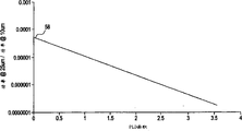
图4是功率比与PLD面积相依性的曲线图。Figure 4 is a graph of power ratio versus PLD area dependence.
图5是本发明绘制的折射率分布曲线图,其中纤芯中央区有四分层。Fig. 5 is a graph of the refractive index distribution drawn by the present invention, wherein there are four layers in the central region of the fiber core.
本发明的详细描述Detailed description of the invention
现在详细参照本发明的诸较佳实施例,实例示于附图。只要可能,附图中将用同样的标号表示同样的部件。图2是本发明单模波导纤维的一示例实施例。虽然图2中折射率分布曲线的各分层示成接近于阶跃形状,具有斜边,但是分层40、43、46与50也可具有α分布曲线形状或带圆角的阶跃折射率、梯形或带圆角的梯形状。纤芯具有若干分层,可调节折射率分布曲线的形状与大小,此灵活性足以实现波导特性的多种组合。图2分布曲线代表的一组分布曲线可产生下述实例1提出的所需特性。该组曲线由下述较佳范围的相对折射率与半径来确定。中央分层40的相对折射率百分比Δ0%约为0.35~0.45%,半径42约为3~5微米。第一环形分层43的相对折射率百分比Δ1%约为0~0.05%,外半径44约为7~9微米。第二环形分层46的相对折射率百分比约Δ2%为0.06~0.20%,外半径48约为9~13微米。PLD 50的相对折射率百分比约Δp%为-0.05~-0.80%,中心半径约为19~21微米。PLD宽度52约为3~10微米。波导纤维用Δ%对半径的这些范围制造,有效面积大于70微米2,更佳的是大于75微米2,最佳的是大于80微米2,1550纳米处的衰减小于0.25dB/km,更佳的是小于0.22dB/km,在1520~1650纳米波长范围内的总色散斜率小于0.09ps/nm2-km,更佳的是小于0.075ps/nm2-km,销钉阵列弯曲损耗小于100dB,更佳的是小于65dB。Reference will now be made in detail to the preferred embodiments of the invention, examples of which are illustrated in the accompanying drawings. Wherever possible, the same reference numerals will be used to refer to the same parts throughout the drawings. Figure 2 is an exemplary embodiment of a single mode waveguide fiber of the present invention. Although the layers of the refractive index profile in FIG. 2 are shown as approximately step-shaped, with sloped sides, the layers 40, 43, 46, and 50 may also have an alpha-profile shape or a step index with rounded corners. , trapezoidal or trapezoidal with rounded corners. The core has several layers to adjust the shape and size of the refractive index profile, which is flexible enough to realize various combinations of waveguide characteristics. A set of profiles represented by the profile of Figure 2 produces the desired properties set forth in Example 1 below. The set of curves is determined by the relative refractive index and radius in the following preferred ranges. The relative refractive index percentage Δ 0 % of the central layer 40 is about 0.35-0.45%, and the radius 42 is about 3-5 microns. The relative refractive index percentage Δ 1 % of the first annular layer 43 is about 0-0.05%, and the outer radius 44 is about 7-9 microns. The relative refractive index percentage of the second annular segment 46 is about Δ 2 % in the range of 0.06-0.20%, and the outer radius 48 is about 9-13 microns. The relative refractive index percentage of the PLD 50 is about Δp % of -0.05--0.80%, and the central radius is about 19-21 microns. PLD width 52 is approximately 3-10 microns. Waveguide fibers are fabricated with these ranges of Δ % versus radius, effective area greater than 70 microns , more preferably greater than 75 microns, most preferably greater than 80 microns , attenuation at 1550 nm less than 0.25 dB/km, more preferably It is less than 0.22dB/km, the total dispersion slope in the wavelength range of 1520-1650 nanometers is less than 0.09ps/nm 2 -km, more preferably less than 0.075ps/nm 2 -km, the pin array bending loss is less than 100dB, more preferably Preferably less than 65dB.
本发明将用下列作为本发明示例的实例来进一步说明。The invention will be further illustrated by the following examples which serve as illustrations of the invention.
实例1Example 1
参照图2,对于图示分布曲线中的各个相对折射率40、43、46和50,Δ0%为0.39%,Δ1%为0,Δ2%为0.085%,PLD的Δp%为-0.3,中央分层外半径42为3.5微米,第一环形分层外半径44为8微米,第二环形分层外半径48为17微米,PLD中心半径为20微米,PLD宽度为4微米。Referring to Fig. 2, for each relative refractive index 40, 43, 46 and 50 in the illustrated distribution curve, Δ 0 % is 0.39%, Δ 1 % is 0, Δ 2 % is 0.085%, and Δ p % of PLD is - 0.3, the outer radius 42 of the central layer is 3.5 microns, the outer radius 44 of the first annular layer is 8 microns, the outer radius 48 of the second annular layer is 17 microns, the central radius of the PLD is 20 microns, and the width of the PLD is 4 microns.
模拟的波导参数是:1550纳米总色散为3.67ps/nm-km,总色散斜率为0.068ps/nm2-km,模场直径为10.6微米,有效面积为86.4微米2,光纤截止波长为1499纳米,销钉阵列弯曲损耗65dB。利用所述曲线,制作1550纳米衰减小于0.20dB/km的光纤。图2所示曲线56表示一功率分布,它与PLD面积约为1.65μm%的模拟曲分布线相关。PLD的作用是锐减纤芯区边缘附近的功率。The simulated waveguide parameters are: 1550nm total dispersion is 3.67ps/nm-km, total dispersion slope is 0.068ps/nm 2 -km, mode field diameter is 10.6 microns, effective area is 86.4 microns 2 , fiber cut-off wavelength is 1499 nanometers , The pin array bending loss is 65dB. Using the curve, an optical fiber with an attenuation of less than 0.20 dB/km at 1550 nm is produced. Curve 56 shown in FIG. 2 represents a power distribution that is associated with a simulated curve distribution of approximately 1.65 .mu.m% of the PLD area. The role of the PLD is to sharply reduce the power near the edge of the core region.
比较例1Comparative example 1
对应于实例1的分布曲线,模拟第二分布曲线,但不包括PLD。在比较例中,模拟的波导参数是:1550纳米总色散为1.18ps/nm-km,总色散斜率为0.058ps/nm2-km,模场直径为10.8微米,有效面积为90.3微米2,光纤截止波长为2213纳米,销钉阵列弯曲损耗为127dB。与该模拟分布曲线有关的功率分布在图2中示为曲线54。在无PLD时,纤芯边缘的功率相对较高,该特性导致销钉阵列宏弯曲损耗比PLD曲线的损耗大2倍。各功率比值(即,将各功率曲线56和54离中心线25微米处的功率除以10微米处的功率)为3×10-5和7.6×10-4。PLD带来的改进超过了一个数量级,从而降低了宏弯曲损耗。此外,功率内移可以改善宏弯曲,对其它波导特性并无任何大的负面影响。Corresponding to the profile of Example 1, a second profile was simulated, but without PLD. In the comparative example, the simulated waveguide parameters are: 1550nm total dispersion is 1.18ps/nm-km, the total dispersion slope is 0.058ps/nm 2 -km, the mode field diameter is 10.8 microns, the effective area is 90.3 microns 2 , the optical fiber The cutoff wavelength is 2213nm, and the pin array bending loss is 127dB. The power distribution associated with this simulated distribution curve is shown as curve 54 in FIG. 2 . In the absence of PLD, the power at the edge of the core is relatively high, and this characteristic results in a pin array macrobending loss that is 2 times larger than that of the PLD curve. The respective power ratios (ie, dividing the power at 25 microns from the centerline by the power at 10 microns for each of the power curves 56 and 54 ) were 3 x 10 -5 and 7.6 x 10 -4 . The improvement brought about by PLD is more than an order of magnitude, resulting in lower macrobend losses. In addition, shifting power inwards improves macrobending without any significant negative impact on other waveguide properties.
图3的分布曲线代表一组能产生下面实例2提出的期望特性的分布曲线。该组分布曲线一般具有一中央纤芯区,该纤芯区包括被PLD包绕的三个分层。该设计尤其适合海底应用场合。这里,各纤芯分层的分布曲线仍可以取图2讨论的各种形状。该组分布曲线由下列较佳范围的相对折射率与半径来确定。中央分层18的相对折射率百分比Δ0%约为0.5~0.6%,外半径26约为2.0~4.5微米。中央分层18被第一环形分层20包绕,后者的相对折射率百分比低于中央分层18,Δ1%约为-0.025~0.01%,外半径28约为5~9微米。第一环形分层20被第二环形分层22包绕,后者的相对折射率百分比Δ2%约为0.06~0.30%,外半径约为11~16微米。PLD 24的相对折射率百分比Δp%约为-0.05~-0.80%,中心半径32约为14~20微米。PLD宽度34约为0.75~13微米。Δp%较佳范围约为-0.2~-0.8%,更佳的是为比-0.25%更负。The distribution curves of Figure 3 represent a set of distribution curves that produce the desired properties set forth in Example 2 below. The set of profiles generally has a central core region comprising three layers surrounded by PLD. This design is especially suitable for subsea applications. Here, the distribution curves of each fiber core layer can still take various shapes as discussed in FIG. 2 . The set of distribution curves is determined by the following preferred ranges of relative refractive index and radius. The relative refractive index percentage Δ 0 % of the central layer 18 is about 0.5-0.6%, and the outer radius 26 is about 2.0-4.5 microns. The central segment 18 is surrounded by a first annular segment 20 having a relative refractive index percentage lower than the central segment 18, Δ 1 % of about -0.025-0.01%, and an outer radius 28 of about 5-9 microns. The first annular layer 20 is surrounded by a second annular layer 22 having a relative refractive index percentage Δ 2 % of about 0.06-0.30% and an outer radius of about 11-16 microns. The relative refractive index percentage Δp % of the PLD 24 is about -0.05--0.80%, and the central radius 32 is about 14-20 microns. PLD width 34 is approximately 0.75-13 microns. The preferred range of Δp % is about -0.2 to -0.8%, more preferably more negative than -0.25%.
利用在这些Δ%与半径范围内的折射率分布曲线制造波导纤维,其有效面积大于约65微米2,更佳的是大于68微米2,最佳的是大于70微米2,并且1550纳米处的衰减小于0.25dB/km,较佳的是小于0.23dB/km,更佳的是小于0.21dB/km,在波长范围1520~1650纳米内的总色散斜率小于0.09ps/nm2-km,更佳的是小于0.08ps/nm2-km,销钉阵列弯曲损耗小于50dB,较佳的是小于35dB,更佳的是小于30dB。微弯曲损耗小于约5dB/m,较佳的是小于3.3dB/m。应用这条折射率分布曲线制作的波导纤维,1550纳米处的衰减小于0.22dB/km。通过布置零色散波长,可使1550纳米的总色散具有正值或负值。光缆化的截止值一般小于1500微米。Utilizing a refractive index profile within these Δ% versus radius ranges to fabricate waveguide fibers having an active area greater than about 65 microns , more preferably greater than 68 microns , most preferably greater than 70 microns , and a The attenuation is less than 0.25dB/km, preferably less than 0.23dB/km, more preferably less than 0.21dB/km, and the total dispersion slope in the wavelength range of 1520-1650 nanometers is less than 0.09ps/nm 2 -km, more preferably It is less than 0.08ps/nm2-km, and the pin array bending loss is less than 50dB, preferably less than 35dB, more preferably less than 30dB. The microbend loss is less than about 5 dB/m, preferably less than 3.3 dB/m. The attenuation at 1550 nm of the waveguide fiber made by using this refractive index distribution curve is less than 0.22dB/km. By placing the zero dispersion wavelength, the total dispersion at 1550 nm can be made positive or negative. The cutoff for cabling is generally less than 1500 microns.
下面用于说明本发明的实例将进一步示明本发明。The following examples illustrating the invention will further illustrate the invention.
实例2Example 2
参照图3,对于图示分布曲线的各相对折射率18、20、22和24,Δ0%为0.54%、Δ1%为-0.02%,Δ2%为0.1%,PLD的Δp%为-0.3%,中央分层半径26为3.0微米,第一环形分层外半径28为5.5微米,第二环形分层外半径30为16微米,PLD的中心半径24为18微米,PLD宽度34为4微米。Referring to Fig. 3, for each relative refractive index 18, 20, 22 and 24 of the illustrated distribution curve, Δ 0 % is 0.54%, Δ 1 % is -0.02%, Δ 2 % is 0.1%, and Δ p % of PLD is -0.3%, the central segment radius 26 is 3.0 microns, the first annular segment outer radius 28 is 5.5 microns, the second annular segment outer radius 30 is 16 microns, the central radius 24 of the PLD is 18 microns, and the PLD width 34 is 4 microns.
模拟的波导参数为:1550微米总色散为-2.91ps/nm-km,在1520~1650纳米范围内的总色散斜率0.077ps/nm2-km,模场直径为9.54微米,有效面积为70.4微米2,光纤截止波长为1675纳米,销钉阵列弯曲损耗为19dB。用这条折射率分布曲线制作的波导纤维在1550纳米处的衰减小于0.22dB/km。与该模拟分布曲线有关的功率分布在图2中示为曲线38。PLD的作用明显减小了纤芯区边缘附近的功率,因而提高了宏弯曲性能。The simulated waveguide parameters are: the total dispersion is -2.91ps/nm-km at 1550 microns, the total dispersion slope is 0.077ps/nm 2 -km in the range of 1520-1650 nanometers, the mode field diameter is 9.54 microns, and the effective area is 70.4 microns 2. The fiber cut-off wavelength is 1675 nm, and the pin array bending loss is 19dB. The attenuation of the waveguide fiber made with this refractive index distribution curve at 1550 nm is less than 0.22dB/km. The power distribution associated with this simulated distribution curve is shown as curve 38 in FIG. 2 . The action of the PLD significantly reduces the power near the edge of the core region, thereby improving the macrobend performance.
比较例2Comparative example 2
对应于实例2的分布曲线,模拟第二分布曲线,但不包含PLD。在该比较例中,模拟的波导参数是:1550纳米的总色散为-4.96ps/nm-km,在1520~1650纳米内的总色散斜率0.068ps/nm2-km,模场直径为9.65微米,有效面积为72.4微米2,光纤截止波长为2333纳米,销钉阵列弯曲损耗为31dB。与该模拟分布曲线有关的功率分布在图2中示为曲线36。在无PLD时,纤芯边缘的功率相对较高,该特征导致销钉阵列宏弯曲损耗比有PLD曲线时的损耗大1.65倍。取有各功率曲线38与36的功率比值(即,将离中心线25微米处的功率除以10微米处的功率)为1.4×10-5和1.6×10-4,改进了一个数量级。这一宏弯曲损耗的改善对其它波导特性无负面影响。Corresponding to the profile of Example 2, a second profile was simulated, but without PLD. In this comparative example, the simulated waveguide parameters are: the total dispersion at 1550 nanometers is -4.96ps/nm-km, the total dispersion slope is 0.068ps/nm 2 -km within 1520-1650 nanometers, and the mode field diameter is 9.65 microns , the effective area is 72.4 microns 2 , the fiber cut-off wavelength is 2333 nm, and the pin array bending loss is 31dB. The power distribution associated with this simulated distribution curve is shown as curve 36 in FIG. 2 . In the absence of PLD, the power at the edge of the core is relatively high, and this feature causes the pin array macrobending loss to be 1.65 times larger than that of the PLD curve. The power ratios (ie, dividing the power at 25 microns from the centerline by the power at 10 microns) with each power curve 38 and 36 are 1.4 x 10 -5 and 1.6 x 10 -4 , an order of magnitude improvement. This improvement in macrobend loss has no negative impact on other waveguide properties.
图5的分布曲线代表一组能产生以下实例3提出的期望特性的分布曲线。该组分布曲线的纤芯中央区包括被PLD包绕的四个分层,该设计适合海底应用。这里,各纤芯分层的分布曲线仍可取上述图2讨论的任何形状,各分层最好落在下述相对折射率与半径的较佳范围内。中央分层60的相对折射率百分比Δ0%约为0.53~0.65%,外半径71约为2.0~2.5微米。中央分层60被第一环形分层62包绕,后者的相对折射率百分比Δ1%比中央分层60低,较佳约为0~0.065%。分层62的外半径72由第二环形分层64的外半径74与宽度80决定。第一环形分层62被第二环形分层64包绕,后者的相对折射率百分比Δ2%约为0.10~0.70%,中心半径73约为8.8~11.8微米,宽度约为0.30~9.0微米。第三环形分层66包绕着第二环形分层64,相对折射率约为0~0.05%,外半径约为75为14.5~16.5微米。PLD 68的相对所射率百分比Δp%约为-0.05~-0.080%,内半径75约为12~19.5微米,外半径77为17~25微米。因此,PLD的最大宽度为13微米。PLD的较佳宽度范围为3~10微米,虽然其取值范围可以是约0.75~1.3微米。相对折射率百分比Δp%约为-0.2~-0.8%,更佳的是为比-0.20%更负的值。The profiles of Figure 5 represent a set of profiles that produce the desired properties set forth in Example 3 below. The central region of the fiber core of this set of profiles includes four layers surrounded by PLD, and this design is suitable for subsea applications. Here, the distribution curve of each fiber core layer can still take any shape discussed in FIG. 2 above, and each layer preferably falls within the following preferred ranges of relative refractive index and radius. The relative refractive index percentage Δ 0 % of the central layer 60 is about 0.53-0.65%, and the outer radius 71 is about 2.0-2.5 microns. The central layer 60 is surrounded by a first annular layer 62 whose relative refractive index percentage Δ 1 % is lower than that of the central layer 60 , preferably about 0-0.065%. The outer radius 72 of the segment 62 is determined by the outer radius 74 and width 80 of the second annular segment 64 . The first annular layer 62 is surrounded by a second annular layer 64 having a relative refractive index percentage Δ2 % of about 0.10-0.70%, a central radius 73 of about 8.8-11.8 microns, and a width of about 0.30-9.0 microns . The third annular layer 66 surrounds the second annular layer 64, has a relative refractive index of about 0-0.05%, and an outer radius of about 75 of 14.5-16.5 microns. The PLD 68 has a relative reflectance percentage Δp % of about -0.05--0.080%, an inner radius 75 of about 12-19.5 microns, and an outer radius 77 of 17-25 microns. Therefore, the maximum width of the PLD is 13 microns. The preferred width of the PLD is in the range of 3-10 microns, although it can be in the range of about 0.75-1.3 microns. The relative refractive index percentage Δp % is about -0.2 to -0.8%, more preferably a value more negative than -0.20%.
在另一实施例中,图5的分布曲线代表一组能产生下面实例3提出的期望特性的分布曲线。该组分布曲线的中央纤芯区包括被PLD包绕的四个分层,该设计尤其适合海底应用。这里,各纤芯分层的分布曲线仍可取上述图2讨论的任何形状,各分层最好落在下列相对折射率与半径的较佳范围内。中央分层60的相对折射率百分比Δ0%约为0.5~0.6%,外半径7 1约为2.4~3.0微米。中央分层60被第一环形分层62包绕,后者的相对折射率比中央分层60低,Δ1%约为0~0.1%,外半径72约为8.4~9.7微米。第一环形分层62被第二环形分层64包绕,后者的相对折射率百分比Δ2%约为0.20~0.30%,外半径74约为10.3~12.6微米。第三环形分层66包绕着第二环形分层64,相对折射率约为0~0.05,外半径75约为14.5~16.5微米。PLD 68的相对折射率百分比约为-0.05~-0.80%,中心半径78约为16.5~20.2微米。该实施例中,PLD宽度70约为6.4~7.9微米,尽管如上所述,其宽度值范围可以为0.75~13微米。Δp%较佳范围约为-0.2~-0.8%,更佳的是为比-0.20%更负。In another embodiment, the distribution curves of FIG. 5 represent a set of distribution curves that produce the desired properties set forth in Example 3 below. The central core region of this set of profiles includes four layers surrounded by PLDs, a design especially suitable for subsea applications. Here, the distribution curve of each fiber core layer can still take any shape discussed in Fig. 2 above, and each layer preferably falls within the following preferred ranges of relative refractive index and radius. The relative refractive index percentage Δ 0 % of the central layer 60 is about 0.5-0.6%, and the outer radius 71 is about 2.4-3.0 microns. The central segment 60 is surrounded by a first annular segment 62 having a lower relative index of refraction than the central segment 60, with a Δ 1 % of about 0-0.1%, and an outer radius 72 of about 8.4-9.7 microns. The first annular segment 62 is surrounded by a second annular segment 64 having a relative refractive index percentage [Delta] 2 % of about 0.20-0.30% and an outer radius 74 of about 10.3-12.6 microns. The third annular layer 66 surrounds the second annular layer 64, has a relative refractive index of about 0-0.05, and an outer radius 75 of about 14.5-16.5 microns. The relative refractive index percentage of PLD 68 is about -0.05--0.80%, and the center radius 78 is about 16.5-20.2 microns. In this embodiment, the PLD width 70 is approximately 6.4-7.9 microns, although as noted above, the width may range in value from 0.75-13 microns. The preferred range of Δp % is about -0.2 to -0.8%, more preferably more negative than -0.20%.
实例3Example 3
参照图5,对于图示分布曲线的各相对折射率60、62、64和66,Δ0%为0.55%、Δ1%为0.01%,Δ2%为0.225%,Δ3%为0,PLD的Δp%为-0.25%,中央分层外半径71为2.37微米,第一环形分层外半径72为8.8微米,第二环形分层外半径74为11.4微米。第三环形分层外半径66为15微米。PLD的中心半径78为18.3微米,PLD宽度70为7.1微米。Referring to Fig. 5, for each relative refractive index 60, 62, 64 and 66 of the illustrated distribution curve, Δ 0 % is 0.55%, Δ 1 % is 0.01%, Δ 2 % is 0.225%, Δ 3 % is 0, PLD Δp % is -0.25%, the central segment outer radius 71 is 2.37 microns, the first annular segment outer radius 72 is 8.8 microns, and the second annular segment outer radius 74 is 11.4 microns. The third annular segment outer radius 66 is 15 microns. The center radius 78 of the PLD is 18.3 microns and the PLD width 70 is 7.1 microns.
按这条曲线制作的波导纤维,1560纳米的总色散为-2.4ps/nm-km,总色散斜率为0.079ps/nm2-km,模场直径为9.36微米,有效面积67.4微米2,光缆化后的截止波长为1378纳米,销钉阵列弯曲损耗为29.6dB。利用该分布曲线制成的光纤在1550纳米处的衰减小于0.22dB/km,通常为0.204dB/km。该示例的微弯曲损耗为3.32dB/m。The waveguide fiber made according to this curve has a total dispersion of -2.4ps/nm-km at 1560 nanometers, a total dispersion slope of 0.079ps/nm 2 -km, a mode field diameter of 9.36 microns, and an effective area of 67.4 microns 2 . The final cut-off wavelength is 1378 nm, and the bending loss of the pin array is 29.6 dB. The attenuation at 1550 nm of the optical fiber made by using this distribution curve is less than 0.22dB/km, usually 0.204dB/km. The microbend loss for this example is 3.32dB/m.
在上述任一实施例中,结合使用更大直径的聚合物涂层时,微弯曲损耗明显减小,一般小于约1dB/m。在更大直径涂层实施例中,在125微米直径的波导纤维上使用了双层涂层,主层或第一层的直径为190±10微米,辅层直径为285±10微米。涂层外直径的上限由实际因素决定,诸如成本与便于架缆等。对于125微米的玻璃光纤直径,涂层直径合理的上限约为310微米。使用辅层直径目标值低达260±10微米的涂层,例如低达250微米的涂层,可改善微弯曲损耗。典型的光纤聚合物涂层是一种以双层聚氨脂丙烯酸酯为基的材料,其模量对于主层小于1.0MPa,对于辅层大于650MPa。在一实施例中,主层模量约为1.0~1.3MPa,辅层的模量约为650~850MPa。In any of the above embodiments, when used in combination with a larger diameter polymer coating, the microbend losses are significantly reduced, typically less than about 1 dB/m. In the larger diameter coating embodiment, a double layer coating was used on a 125 micron diameter waveguide fiber, with a primary or first layer having a diameter of 190 ± 10 microns and a secondary layer having a diameter of 285 ± 10 microns. The upper limit of the outer diameter of the coating is determined by practical factors such as cost and ease of cable erection. For a glass fiber diameter of 125 microns, a reasonable upper limit to coating diameter is about 310 microns. Microbending losses can be improved by using coatings with sublayer diameter targets as low as 260 ± 10 microns, eg, as low as 250 microns. A typical optical fiber polymer coating is a two-layer polyurethane acrylate-based material with a modulus of less than 1.0 MPa for the main layer and greater than 650 MPa for the auxiliary layer. In one embodiment, the modulus of the main layer is about 1.0-1.3 MPa, and the modulus of the auxiliary layer is about 650-850 MPa.
实例4Example 4
制作一波导纤维并对其进行测量。该波导纤维的参数符合实例3的参数,其聚合物涂层包绕上述提出的大直径包层。测得的参数是:1560纳米处的总色散为-2.3ps/nm-km,总色散斜率为0.078ps/nm2-km,模场直径为9.25微米,有效面积为66微米2,光缆化后的截止波长为1435纳米,销钉阵列弯曲损耗为4.7dB,1550纳米处的衰减为0.196,微弯曲损耗为0.64dB/m。Fabricate a waveguide fiber and measure it. The parameters of this waveguide fiber correspond to those of Example 3 with the polymer coating surrounding the large diameter cladding proposed above. The measured parameters are: the total dispersion at 1560 nanometers is -2.3ps/nm-km, the total dispersion slope is 0.078ps/nm 2 -km, the mode field diameter is 9.25 microns, and the effective area is 66 microns 2 . The cutoff wavelength is 1435nm, the pin array bending loss is 4.7dB, the attenuation at 1550nm is 0.196, and the microbending loss is 0.64dB/m.
本说明书提出的发明基本上可以适用于任何折射率分布曲线,以改善抗弯曲性,但几乎不改变其它波导纤维特性。图4的曲线58示出了当PLD面积增大时,25微米与10微米功率比的变化。曲线58对不同折射率分布曲线产生的一系列点的最佳拟合。对于较低的PLD值,即约小于1的那些值,围绕拟合线扩展的功率比数据点为7×10⁻⁵。在较大PLD面积时,功率比扩展约为2.2×10⁻⁵。随着PLD面积的增大,宏弯曲损耗的改善变得很少依赖于PLD分层内侧各纤芯分层的分布细节。对于大量设计在1250~1700微米波长带的分布曲线而言,都可从本发明获益。The invention presented in this specification can be applied to essentially any refractive index profile to improve bending resistance with little change to other waveguide fiber characteristics.
本领域的技术人员将明白,可以不背离本发明的精神与范围对本发明作各种修正与变动。因此,只要符合所附权利要求及其等效技术方案的范围,本发明包括对本发明的修正与变动。It will be apparent to those skilled in the art that various modifications and changes can be made in the present invention without departing from the spirit and scope of the invention. Therefore, the present invention includes the modifications and variations of the present invention as long as they comply with the scope of the appended claims and their equivalent technical solutions.
Claims (37)
Applications Claiming Priority (4)
| Application Number | Priority Date | Filing Date | Title |
|---|---|---|---|
| US14575999P | 1999-07-27 | 1999-07-27 | |
| US60/145,759 | 1999-07-27 | ||
| US16583399P | 1999-11-16 | 1999-11-16 | |
| US60/165,833 | 1999-11-16 |
Publications (2)
| Publication Number | Publication Date |
|---|---|
| CN1377472A CN1377472A (en) | 2002-10-30 |
| CN1237356C true CN1237356C (en) | 2006-01-18 |
Family
ID=26843267
Family Applications (1)
| Application Number | Title | Priority Date | Filing Date |
|---|---|---|---|
| CNB008109559A Expired - Fee Related CN1237356C (en) | 1999-07-27 | 2000-06-20 | Fiber with Power Limiting Notches |
Country Status (10)
| Country | Link |
|---|---|
| US (1) | US6317551B1 (en) |
| EP (1) | EP1116059A4 (en) |
| JP (1) | JP2004500590A (en) |
| KR (1) | KR20020038703A (en) |
| CN (1) | CN1237356C (en) |
| AU (1) | AU7824500A (en) |
| BR (1) | BR0012719A (en) |
| CA (1) | CA2380720A1 (en) |
| MX (1) | MXPA02000925A (en) |
| WO (1) | WO2001011402A1 (en) |
Families Citing this family (39)
| Publication number | Priority date | Publication date | Assignee | Title |
|---|---|---|---|---|
| US6031956A (en) * | 1997-11-17 | 2000-02-29 | Corning Incorporated | High performance single mode waveguide |
| US6396986B1 (en) * | 1998-04-22 | 2002-05-28 | Corning Incorporated | Method of making optical fibers |
| US6442320B1 (en) * | 1999-04-16 | 2002-08-27 | Lasercomm Inc. | Limited mode dispersion compensating optical fiber |
| EP1107028A4 (en) * | 1999-05-17 | 2007-08-22 | Furukawa Electric Co Ltd | Optical fiber and optical transmission line comprising the optical fiber |
| US6424778B1 (en) * | 1999-09-29 | 2002-07-23 | Corning Incorporated | Optical fiber with large effective area and low dispersion slope for submarine applications |
| US6611647B2 (en) * | 2000-12-12 | 2003-08-26 | Corning Incorporated | Large effective area optical fiber |
| US6483975B1 (en) * | 2001-04-27 | 2002-11-19 | Fitel Usa Corp. | Positive dispersion optical fiber having large effective area |
| JP2003004995A (en) | 2001-06-26 | 2003-01-08 | Fujikura Ltd | Dispersion compensating optical fiber and dispersion compensating optical fiber module |
| US6789960B2 (en) | 2001-07-06 | 2004-09-14 | Corning Incorporated | Method of connecting optical fibers, an optical fiber therefor, and an optical fiber span therefrom |
| US6801699B1 (en) | 2001-11-15 | 2004-10-05 | Corning Incorporated | High capacity optical waveguide fiber |
| AU2002342178A1 (en) * | 2001-11-15 | 2003-06-10 | Corning Incorporated | High capacity optical waveguide fiber |
| US6810185B2 (en) | 2002-01-31 | 2004-10-26 | Corning Incorporated | Higher order mode stripping optical fiber and modules and systems utilizing the same |
| KR20040075982A (en) * | 2002-02-15 | 2004-08-30 | 코닝 인코포레이티드 | Low slope dispersion shifted optical fiber |
| US6771865B2 (en) * | 2002-03-20 | 2004-08-03 | Corning Incorporated | Low bend loss optical fiber and components made therefrom |
| CN1310045C (en) * | 2002-10-01 | 2007-04-11 | 古河电气工业株式会社 | Optical fiber, optical transmission line and method for manufacturing optical fiber |
| US20040076392A1 (en) * | 2002-10-17 | 2004-04-22 | Bickham Scott R. | Low Kappa, dual-moat DC fiber and optical transmission line |
| US6856743B2 (en) * | 2002-12-02 | 2005-02-15 | Corning Incorporated | NZDSF optical fiber with low dispersion zero and low slope |
| US6904217B2 (en) * | 2003-01-29 | 2005-06-07 | Furukawa Electric North America | Method for the manufacture of optical fibers, improved optical fibers, and improved Raman fiber amplifier communication systems |
| US6959137B2 (en) * | 2003-06-11 | 2005-10-25 | Fitel U.S.A. Corporation | Large-effective-area inverse dispersion compensating fiber, and a transmission line incorporating the same |
| FR2893149B1 (en) * | 2005-11-10 | 2008-01-11 | Draka Comteq France | OPTICAL FIBER MONOMODE. |
| FR2899693B1 (en) * | 2006-04-10 | 2008-08-22 | Draka Comteq France | OPTICAL FIBER MONOMODE. |
| US7505660B2 (en) * | 2006-06-30 | 2009-03-17 | Corning Incorporated | Microstructured transmission optical fiber |
| US7450807B2 (en) * | 2006-08-31 | 2008-11-11 | Corning Incorporated | Low bend loss optical fiber with deep depressed ring |
| US7620282B2 (en) * | 2006-08-31 | 2009-11-17 | Corning Incorporated | Low bend loss single mode optical fiber |
| US20080205839A1 (en) * | 2007-02-28 | 2008-08-28 | Scott Robertson Bickham | Large effective area high SBS threshold optical fiber |
| DK2206001T3 (en) * | 2007-11-09 | 2014-07-07 | Draka Comteq Bv | Optical fiber resistant to microbending |
| US7853110B2 (en) * | 2007-11-28 | 2010-12-14 | Corning Incorporated | Large effective area optical fiber |
| FR2930997B1 (en) * | 2008-05-06 | 2010-08-13 | Draka Comteq France Sa | OPTICAL FIBER MONOMODE |
| US7570857B1 (en) * | 2008-05-08 | 2009-08-04 | Corning Incorporated | Low bend loss dispersion slope compensating optical fiber |
| US7773848B2 (en) | 2008-07-30 | 2010-08-10 | Corning Incorporated | Low bend loss single mode optical fiber |
| US7676129B1 (en) | 2008-11-18 | 2010-03-09 | Corning Incorporated | Bend-insensitive fiber with two-segment core |
| KR101627830B1 (en) * | 2009-02-16 | 2016-06-08 | 엘에스전선 주식회사 | A non-zero dispersion shifted optical fiber and optical transmission line using the same, and optical transmission system |
| JP2012076962A (en) * | 2010-10-01 | 2012-04-19 | Sumitomo Electric Ind Ltd | Method for manufacturing glass preform for optical fiber and optical fiber |
| US9042692B2 (en) * | 2013-08-27 | 2015-05-26 | Corning Cable Systems Llc | Universal optical fibers for optical fiber connectors |
| JP2016148749A (en) * | 2015-02-12 | 2016-08-18 | 株式会社フジクラ | Dispersion shifted optical fiber |
| CN104880766B (en) * | 2015-06-25 | 2018-01-12 | 长飞光纤光缆股份有限公司 | A kind of ultralow decay single-mode fiber |
| CN104898201B (en) * | 2015-06-25 | 2017-12-08 | 长飞光纤光缆股份有限公司 | A kind of single-mode fiber of ultralow attenuation large effective area |
| JP6682826B2 (en) * | 2015-11-27 | 2020-04-15 | 住友電気工業株式会社 | Optical fiber and light source device |
| CN109839694B (en) * | 2017-11-27 | 2020-08-18 | 中天科技精密材料有限公司 | Single mode fiber with cut-off wavelength displacement |
Family Cites Families (13)
| Publication number | Priority date | Publication date | Assignee | Title |
|---|---|---|---|---|
| US4715679A (en) * | 1981-12-07 | 1987-12-29 | Corning Glass Works | Low dispersion, low-loss single-mode optical waveguide |
| US4852968A (en) * | 1986-08-08 | 1989-08-01 | American Telephone And Telegraph Company, At&T Bell Laboratories | Optical fiber comprising a refractive index trench |
| US5448674A (en) * | 1992-11-18 | 1995-09-05 | At&T Corp. | Article comprising a dispersion-compensating optical waveguide |
| US5278931A (en) * | 1992-12-31 | 1994-01-11 | Corning Incorporated | Low bend loss singlemode optical waveguide fiber |
| US5553185A (en) * | 1994-12-27 | 1996-09-03 | Corning Incorporated | Controlled dispersion optical waveguide |
| US5835655A (en) * | 1995-01-26 | 1998-11-10 | Corning Incorporated | Large effective area waveguide fiber |
| TW342460B (en) | 1996-01-16 | 1998-10-11 | Sumitomo Electric Industries | A dispersion shift fiber |
| JP3369389B2 (en) | 1996-02-08 | 2003-01-20 | 住友電気工業株式会社 | Dispersion shifted optical fiber |
| US5684909A (en) * | 1996-02-23 | 1997-11-04 | Corning Inc | Large effective area single mode optical waveguide |
| US5781684A (en) * | 1996-12-20 | 1998-07-14 | Corning Incorporated | Single mode optical waveguide having large effective area |
| CA2225889A1 (en) | 1996-12-27 | 1998-06-27 | Sumitomo Electric Industries, Ltd. | Dispersion-shifted fiber |
| JP3830636B2 (en) * | 1997-10-14 | 2006-10-04 | 株式会社フジクラ | Dispersion-shifted optical fiber |
| DE19745760A1 (en) | 1997-10-16 | 1999-04-22 | Daimler Chrysler Ag | Front wall for a motor vehicle |
-
2000
- 2000-06-20 CA CA002380720A patent/CA2380720A1/en not_active Abandoned
- 2000-06-20 EP EP00968309A patent/EP1116059A4/en not_active Withdrawn
- 2000-06-20 AU AU78245/00A patent/AU7824500A/en not_active Abandoned
- 2000-06-20 WO PCT/US2000/016925 patent/WO2001011402A1/en not_active Ceased
- 2000-06-20 JP JP2001515999A patent/JP2004500590A/en active Pending
- 2000-06-20 BR BR0012719-1A patent/BR0012719A/en not_active Application Discontinuation
- 2000-06-20 KR KR1020027001075A patent/KR20020038703A/en not_active Withdrawn
- 2000-06-20 CN CNB008109559A patent/CN1237356C/en not_active Expired - Fee Related
- 2000-06-20 MX MXPA02000925A patent/MXPA02000925A/en unknown
- 2000-06-27 US US09/604,498 patent/US6317551B1/en not_active Expired - Lifetime
Also Published As
| Publication number | Publication date |
|---|---|
| KR20020038703A (en) | 2002-05-23 |
| AU7824500A (en) | 2001-03-05 |
| WO2001011402A1 (en) | 2001-02-15 |
| CN1377472A (en) | 2002-10-30 |
| MXPA02000925A (en) | 2002-07-30 |
| EP1116059A1 (en) | 2001-07-18 |
| JP2004500590A (en) | 2004-01-08 |
| US6317551B1 (en) | 2001-11-13 |
| EP1116059A4 (en) | 2005-07-20 |
| BR0012719A (en) | 2002-04-09 |
| CA2380720A1 (en) | 2001-02-15 |
Similar Documents
| Publication | Publication Date | Title |
|---|---|---|
| CN1237356C (en) | Fiber with Power Limiting Notches | |
| CN1105929C (en) | Large effective area single mode optical waveguide | |
| CN1111751C (en) | Dispersion flat optical fiber | |
| CN1100273C (en) | Dispersion compensating single mode waveguide | |
| CN1217475A (en) | Low-attenuation light-wave guide | |
| CN1206552C (en) | Positive dispersion low dispersion slope fiber | |
| CN101059585A (en) | Hole-assisted single mode optical fiber | |
| CN1114114C (en) | Waveguide profile for large effective area | |
| CN1094202C (en) | dispersion shifted fiber | |
| CN1391657A (en) | Dispersion shifted large effective area waveguide fiber | |
| US20230324606A1 (en) | Optical fiber | |
| JPH08248251A (en) | Single-mode optical waveguide fiber | |
| CN1550802A (en) | Ultra-large effective area optical fiber and communication system including such optical fiber | |
| CN1115574C (en) | High Performance Single Mode Fiber | |
| CN1439107A (en) | Dispersion slope compensating optical fiber | |
| HK1044380A1 (en) | Optical fiber and optical communication system using this optical fiber | |
| CN1294432C (en) | Dispersion-shifted single-mode fiber with large effective cross-section | |
| CN1377469A (en) | Low dispersion slope waveguide fiber | |
| CN1303484A (en) | Optical fiber | |
| CN1182412C (en) | Low-slope dispersion-shifted single-mode fiber for high-capacity transmission | |
| CN1163768C (en) | Optical Fiber with Low Dispersion Gradient | |
| CN1134680C (en) | Single Mode Waveguide for Long Reach | |
| CN1376273A (en) | Optical fiber with large effective area and low dispersion slope for submarine applications | |
| CN1133885C (en) | Optical fiber for extended wavelength band | |
| CN1309780A (en) | Single mode optical waveguide |
Legal Events
| Date | Code | Title | Description |
|---|---|---|---|
| C10 | Entry into substantive examination | ||
| SE01 | Entry into force of request for substantive examination | ||
| C06 | Publication | ||
| PB01 | Publication | ||
| C10 | Entry into substantive examination | ||
| SE01 | Entry into force of request for substantive examination | ||
| C14 | Grant of patent or utility model | ||
| GR01 | Patent grant | ||
| CF01 | Termination of patent right due to non-payment of annual fee |
Granted publication date: 20060118 Termination date: 20150620 |
|
| EXPY | Termination of patent right or utility model |