CN1237393A - Elastic ends for rods and rods fitted with such ends - Google Patents

Elastic ends for rods and rods fitted with such ends Download PDF

Info

Publication number
CN1237393A
CN1237393A CN99105335A CN99105335A CN1237393A CN 1237393 A CN1237393 A CN 1237393A CN 99105335 A CN99105335 A CN 99105335A CN 99105335 A CN99105335 A CN 99105335A CN 1237393 A CN1237393 A CN 1237393A
Authority
CN
China
Prior art keywords
termination
rod
elasticity
housed
elastically deformable
Prior art date
Legal status (The legal status is an assumption and is not a legal conclusion. Google has not performed a legal analysis and makes no representation as to the accuracy of the status listed.)
Granted
Application number
CN99105335A
Other languages
Chinese (zh)
Other versions
CN1204843C (en
Inventor
山本善和
野村保夫
Current Assignee (The listed assignees may be inaccurate. Google has not performed a legal analysis and makes no representation or warranty as to the accuracy of the list.)
Daiwa Co Ltd
Original Assignee
Daiwa Co Ltd
Priority date (The priority date is an assumption and is not a legal conclusion. Google has not performed a legal analysis and makes no representation as to the accuracy of the date listed.)
Filing date
Publication date
Application filed by Daiwa Co Ltd filed Critical Daiwa Co Ltd
Publication of CN1237393A publication Critical patent/CN1237393A/en
Application granted granted Critical
Publication of CN1204843C publication Critical patent/CN1204843C/en
Anticipated expiration legal-status Critical
Expired - Fee Related legal-status Critical Current

Links

Images

Classifications

    • AHUMAN NECESSITIES
    • A45HAND OR TRAVELLING ARTICLES
    • A45BWALKING STICKS; UMBRELLAS; LADIES' OR LIKE FANS
    • A45B1/00Sticks with supporting, hanging or carrying means
    • AHUMAN NECESSITIES
    • A45HAND OR TRAVELLING ARTICLES
    • A45BWALKING STICKS; UMBRELLAS; LADIES' OR LIKE FANS
    • A45B9/00Details
    • A45B9/04Ferrules or tips
    • AHUMAN NECESSITIES
    • A61MEDICAL OR VETERINARY SCIENCE; HYGIENE
    • A61HPHYSICAL THERAPY APPARATUS, e.g. DEVICES FOR LOCATING OR STIMULATING REFLEX POINTS IN THE BODY; ARTIFICIAL RESPIRATION; MASSAGE; BATHING DEVICES FOR SPECIAL THERAPEUTIC OR HYGIENIC PURPOSES OR SPECIFIC PARTS OF THE BODY
    • A61H3/00Appliances for aiding patients or disabled persons to walk about
    • A61H3/02Crutches
    • A61H3/0288Ferrules or tips therefor

Landscapes

  • Health & Medical Sciences (AREA)
  • Epidemiology (AREA)
  • Pain & Pain Management (AREA)
  • Physical Education & Sports Medicine (AREA)
  • Rehabilitation Therapy (AREA)
  • Life Sciences & Earth Sciences (AREA)
  • Animal Behavior & Ethology (AREA)
  • General Health & Medical Sciences (AREA)
  • Public Health (AREA)
  • Veterinary Medicine (AREA)
  • Walking Sticks, Umbrellas, And Fans (AREA)

Abstract

本发明是提供一种无可动部分和滑动部分的棍用端头及采用该端头的棍,该端头整体形成、易于变形、具有恢复功能并且结构简单。本发明端头主要由如下部分构成:用于与地面接触的下部1,设有一棍3用插入开孔6的上部2,及用于连接下部1和上部2并且其外表面上设有一环形凹槽5的弹性可变形部分4。上述三个部分1、2和4由一种弹性材料整体制成。

Figure 99105335

The present invention provides a stick end without movable parts and sliding parts and a stick using the end. The end is integrally formed, easy to deform, has recovery function and has a simple structure. The terminal of the present invention is mainly composed of the following parts: a lower part 1 for contacting the ground, an upper part 2 with a stick 3 inserted into the opening 6, and an annular recess for connecting the lower part 1 and the upper part 2 and an outer surface thereof. The elastically deformable part 4 of the slot 5 . The above-mentioned three parts 1, 2 and 4 are integrally made of an elastic material.

Figure 99105335

Description

Rod is with the elasticity termination and the rod of this termination is housed
The present invention relates to a kind of various rods that are used for, the elasticity termination of for example singlehanded cane, crutch etc. more particularly, relates to and is used for the elasticity termination on the elderly, disabled person and the rehabilitation patient's cane and the rod of this termination is housed.
Above-mentioned up to now various forms of rods all are known, and all are equipped with one on nearly all these rods and are in rod elasticity termination bottom by what form such as rubber etc.
In recent years, adopted the movable termination of elasticity of ball-and-socket head by known.
For last described elasticity termination, if the ground maintenance is vertical relatively in use for rod, this termination can tentatively reach and prevent to bludgeon sliding purpose.But, in common walking process, owing to be difficult to keep the relative ground of rod vertical always, in the time of for example on a slope or a step etc. under the situation, so rod is face tilt use relatively often, because thereby the termination at first lacks enough contacts area between kiss the earth termination and the ground, so can not reach enough skidproof effects.Also promptly, a problem of existence, promptly the skidproof effect of termination can not guarantee that the user has very high security.
On the other hand, although one termination, back has solved this problem and has overcome the deficiency of last termination,, it is complicated that the structure of termination is tending towards, because it is according to the socket arrangement manufacturing.In addition, the moving part that surrounds ball is exposed to the outside as slipper, therefore the dust and the grains of sand that scatter on the road are easy to enter inside by the gap that forms between moving part and the ball, thereby cause another problem, and promptly these dusts and the grains of sand will become the source of doing evil of mechanical breakdown.
Implementing the present invention just can address the above problem.An object of the present invention is to provide a kind of termination that is used for rod and with the rod of this termination, this termination does not comprise that promptly moving part does not comprise slide unit yet, this termination forms the structure of holistic and elastically deformable and simple in structure and have a restore funcitons.
The present invention can address the above problem, if it is by constituting as lower member:
(1) one is used for the elasticity termination of rod, and this termination comprises:
One is used for the bottom, termination that contacts with ground;
Top, one termination, this top, termination have a rod patchhole so that insert rod; And
One is used for the strain part that the upper and lower is continuous, and this part is provided with an annular groove that is on the outer surface, wherein:
Above-mentioned three parts form by an elastomeric material is whole.
(2) one are used for the elasticity termination of rod, comprising:
One is used for the bottom, termination that contacts with ground;
Top, one termination, this top, termination have a rod patchhole so that insert rod; And
One is used for strain part that the bottom is linked to each other with top, and this part is provided with an annular groove that is on the outer surface, wherein:
Above-mentioned three parts form by a kind of elastomeric material is whole; And
For example a helical spring, a cord spare (cord) etc. are embedded into and are fixed in the elastomeric material to be used to strengthen the reinforcing material of above-mentioned elastomeric material.
(3) the elasticity termination of basis (1) or (2) described structure, wherein:
Lining is put a kind of tubular metal on the inwall in the hole of being opened on top, termination.
(4) the elasticity termination of basis (1) or (2) described structure, wherein:
Be lined with a kind of tubular metal on the inwall in the hole of being opened on top, termination; And
On the neighboring on top, termination, be covered with a kind of enhancing light material.
(5) rod of (1) described termination is housed, and this termination places rod bottom.
(6) rod of (2) described termination is housed, and this termination places rod bottom.
(7) rod of (3) described termination is housed, and this termination places rod bottom.
(8) rod of (4) described termination is housed, and this termination places rod bottom.
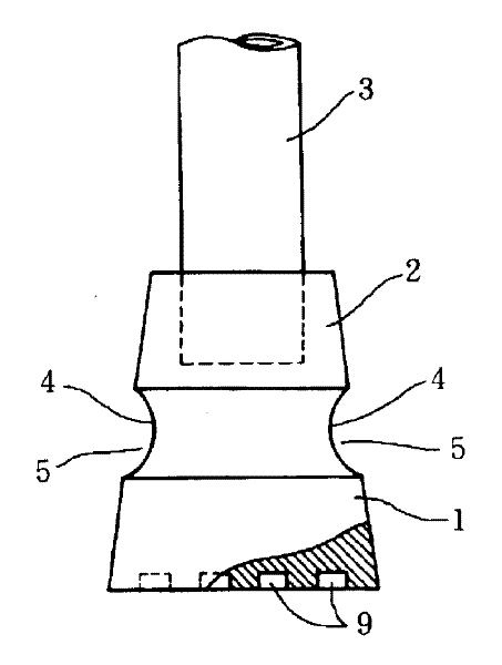
Fig. 1 is that rod of the present invention cuts open side view with the office of one of elasticity termination embodiment;
Fig. 2 is that side view cuts open in the office of another embodiment of the present invention;
Fig. 3 A is that side view cuts open in the office of another embodiment of the present invention;
Fig. 3 B is the horizontal sectional drawing of being done along the B-B line among Fig. 3;
Fig. 4 is that side view cuts open in the office of another embodiment of the present invention;
Fig. 5 A, 5B, 5C and 5D are some side views, and these side views progressively show the strain process of the embodiment of the invention that is in user mode after the termination is contained on the rod.
Describe most preferred embodiment of the present invention in detail below in conjunction with accompanying drawing 1 to 5D.The optimal mode that the inventor expects in implementing process of the present invention in addition corresponding most preferred embodiment is described.
In each accompanying drawing, on behalf of the termination, icon 1 be used for the bottom of kiss the earth, 2 represent the top of termination, the termination is contained in the lower end of rod 3,4 represent an elastically deformable part, this part 4 is formed between above-mentioned bottom 1 and the top 2 so that these two parts are linked to each other, and this part 4 is provided with an annular groove 5 in its surface.The bottom 1 of termination, elastically deformable part 4 and top 2 by a kind of elastomeric material for example integral body such as rubber, plastic resin make to form an elongated body circular cone that cuts.6 holes of representing on the termination 2 front end to open herein, the lower end of rod can be inserted and secured on wherein.
Fig. 2,3,4A and 4B show some structures, and inside, termination all is embedded with and is fixed with reinforcement 7 in every kind of structure, this and shown in Figure 1 distinguishing to some extent at preceding embodiment.
In the embodiment shown in Figure 2, establish the helical spring 7a that an elastic strength suits the requirements in the termination, the position of this spring is corresponding with the height of annular groove 5 basically, perhaps the termination is whole forms, for example form, form rear coil springs 7a and be enclosed in inside by a kind of continuous die casting technology of employing one mould is whole. Circular baffle plate 8 and 8 preferably and two end in contact up and down of helical spring 7a. Circular baffle plate 8 and 8 also forms one with the termination, or adopts mould to form this termination, or together embeds inside, termination with helical spring 7a.
When adopting burying technology, if utilize the hole 6 of going deep into the termination, plectane 8 and 8 and the embedding of helical spring 7a and fixedly be easy to reach.
In the embodiment shown in Fig. 3 A and the 3B, one rigid pipe 6a just as metal tube, also embeds and is fixed on 6 inside, hole, to scheme with rod in embodiment illustrated in fig. 2, directly scribbling a kind of adhesive on the rubber than more reliable more firmly being fixed in the hole 6 embodiment illustrated in fig. 2.On 2 outer surface on the termination, also be covered with a reflecting plate L, to scheme the reflecting light that sends from an automobile, street lamp etc. efficiently.
Even said structure is not only guaranteed also can walk safely at night, and prevented that the termination is from the unexpected landing of rod end.
Reflecting plate L can be by a kind of colored transparent component manufacturing, and this member is formed by the known plastic resin that is suitable for being colored, thereby or attracting notice, or give a kind of dangerous state, for example redness, yellow etc. warned.Reflecting plate L can be by a kind of resin molded technology manufacturing to have the shape of a taper, and this shape is consistent with the profile on top 2, perhaps can be adhered on the part 2 by a kind of adhesive and formed by (fan-shaped) part that blocks of plane institution movement.
In the embodiment shown in fig. 4, a cylindric cotton tyre cord 7b replaces helical spring 7a shown in Figure 2 to embed and is fixed in the termination.This cotton tyre cord spare (tire cord) 7b preferably utilize mould when molded rubber spare and the shell of termination form one.In the present embodiment, consistent with the embodiment shown in prior figures 2 and the 3A, circular baffle plate 8 and 8 places respectively and contacted position, the top and bottom of cord spare 7b.Have hole 6 on the termination on 2 the front surface too, the end of rod 3 can be inserted in this hole so that a kind of service is provided.
In every width of cloth figure, 9 all represent a non slip surface, and this non slip surface is inhomogeneous to be formed under the termination on 1 the bottom.
Even if for other embodiment outside Fig. 3 A and the 3B illustrated embodiment, also can adopt rigid pipe 6a or reflecting plate L selectively.
Because the present invention has adopted said structure, the end of rod 3 just can be inserted and secured in the hole 6 securely so that be user's service.
If in rod 3 inclination uses, in a single day bottom 1 contacts with ground, and 1 of this part of rod 3 keeps nonslipping contact condition with ground all the time, and Fig. 5 A, 5B, 5C and 5D show the deformation process of termination when the user walks successively.In Fig. 5 A, 5B and 5C, mainly be that the annular groove 5 that is used for connecting the elastically deformable part 4 on bottom 1 and top 2 is compressed at the incline direction of rod, then be stretched at other direction, thereby cause local deformation, this distortion just can guarantee that the user stably uses rod 3.
Have again, if helical spring 7a or cord 7b are embedded into inside, termination, among the embodiment shown in Fig. 2,3A, 3B and 4, it can strengthen the elastomeric material of outside, this just makes used rubber can have relatively low hardness, thereby can improve flexibility and can reduce manufacturing cost.
After making the termination main body according to technology of the present invention by a kind of elastomeric material is whole,, there are not the part of any slip or the seam intrusion termination that can prevent the grains of sand, rainwater etc. fully partially even strain takes place in the termination yet.Therefore, just can avoid the generation of material aging and component failure phenomenon fully so that with respect to existing termination the service life of termination of the present invention can prolong a lot.Because the intrinsic constructional simplicity of the present invention, termination of the present invention can be installed in any rod bottom, as long as the user is ready.
When the user uses the rod that termination of the present invention is housed to help walking, this rod is not only convenient but also also convenient to the disabled person to the elderly, even it is also helpful to rehabilitation patient or injured people, because the basal surface of termination of the present invention remains and the ground state of contact, no matter rod is with which kind of angle face tilt relatively, the distortion of termination all can be absorbed by the telescopic action of annular groove.Cover on reflecting plate on the outer surface of termination and can reflect light that headlight for vehicles etc. sends at night effectively attracting driver's attention, thereby can prevent unexpected accident.Embed rigid pipe in the termination make bonding between termination and the rod and fix more reliable, thereby can avoid the termination unexpectedly to come off from rod.

Claims (8)

1. elasticity termination that is used for rod comprises:
One is used for the bottom that contacts with ground;
A top, this top have a rod patchhole, and described rod can insert in this hole; And
One is used for elastically deformable part that described bottom is linked to each other with described top, and the outer surface of this elastically deformable part is provided with an annular groove, wherein:
Above-mentioned three parts form by a kind of elastomeric material is whole.
2. elasticity termination that is used for rod comprises:
One is used for the bottom that contacts with ground;
A top, this top have a rod patchhole, and described rod can insert in this hole; And
One is used for elastically deformable part that described bottom is linked to each other with described top, and the outer surface of this elastically deformable part is provided with an annular groove, wherein:
Above-mentioned three parts form by a kind of elastomeric material is whole; And
Described elastomeric material is embedded in and is fixed with a kind of reinforcing material that is used to strengthen this elastomeric material, for example helical spring, cord spare (cord) etc.
3. elasticity as claimed in claim 1 or 2 termination is characterized in that: lining is put a tubular metal on the inwall of the perforate of processing on the described termination.
4. elasticity as claimed in claim 1 or 2 termination is characterized in that: lining is put a tubular metal on the inwall of the perforate of processing on the described termination; And
Be covered with a kind of reflectorized material that is used for reflection ray on the outer surface on the described top of described termination.
5. the rod that the described termination of claim 1 is housed is characterized in that, described termination is in described rod bottom.
6. the rod that the described termination of claim 2 is housed is characterized in that, described termination is in described rod bottom.
7. the rod that the described termination of claim 3 is housed is characterized in that, described termination is in described rod bottom.
8. the rod that the described termination of claim 4 is housed is characterized in that, described termination is in described rod bottom.
CNB991053354A 1998-06-02 1999-04-30 Elastic ends for rods and rods fitted with such ends Expired - Fee Related CN1204843C (en)

Applications Claiming Priority (6)

Application Number Priority Date Filing Date Title
JP15292898 1998-06-02
JP152928/1998 1998-06-02
JP152928/98 1998-06-02
JP6922/99 1999-01-13
JP6922/1999 1999-01-13
JP11006922A JP2000050927A (en) 1998-06-02 1999-01-13 Flexible elastic feet for canes and their canes

Publications (2)

Publication Number Publication Date
CN1237393A true CN1237393A (en) 1999-12-08
CN1204843C CN1204843C (en) 2005-06-08

Family

ID=26341145

Family Applications (1)

Application Number Title Priority Date Filing Date
CNB991053354A Expired - Fee Related CN1204843C (en) 1998-06-02 1999-04-30 Elastic ends for rods and rods fitted with such ends

Country Status (6)

Country Link
US (1) US6374841B1 (en)
EP (1) EP0962163A1 (en)
JP (1) JP2000050927A (en)
KR (1) KR20000005626A (en)
CN (1) CN1204843C (en)
AU (1) AU2251299A (en)

Cited By (1)

* Cited by examiner, † Cited by third party
Publication number Priority date Publication date Assignee Title
CN109893406A (en) * 2019-04-08 2019-06-18 石家庄德度光电科技有限公司 Footing and walk help brace

Families Citing this family (44)

* Cited by examiner, † Cited by third party
Publication number Priority date Publication date Assignee Title
CA2273397C (en) * 1998-06-09 2003-11-18 Gerald Harris Overboot for a bi-pod adapter
EP1048242A3 (en) * 1999-04-28 2002-11-13 Kabushiki Kaisha Daiwa Flexibly elastic and light reflective tip for sticks
JP2002028012A (en) * 2000-07-13 2002-01-29 Daiwa:Kk Flexible elastic feet for canes
JP2002034624A (en) * 2000-07-25 2002-02-05 Daiwa:Kk Foot Adapter
KR20010074239A (en) * 2001-04-12 2001-08-04 김일구 Stick
US20040025918A1 (en) * 2002-08-06 2004-02-12 Jeremy Gin Mobility-aid apparatus and method having ground contact pad without intervening washer
US20040025919A1 (en) * 2002-08-06 2004-02-12 Jesus Garza Apparatus and method for maintaining ground contact of a mobility-aid apparatus at varying angles
US7270138B2 (en) * 2002-10-22 2007-09-18 Hsueh-Hu Liao Joint mechanism
JP4139192B2 (en) * 2002-11-19 2008-08-27 中井 律子 Preheating cooking method of food
US20040144410A1 (en) * 2003-01-24 2004-07-29 Cheng Tung Cheng Ergonomic walking cane
USD603302S1 (en) 2003-10-07 2009-11-03 Phillip Minyard Willis Frame for support device
US20080129016A1 (en) * 2006-01-31 2008-06-05 Phillip Minyard Willis Mobile support assembly
US9173802B2 (en) 2003-10-07 2015-11-03 Amg Medical, Usa. Mobile support assembly
US7926834B2 (en) * 2003-10-07 2011-04-19 AMG Medical, USA Mobile support assembly
USD572632S1 (en) 2003-10-07 2008-07-08 Phillip Minyard Willis Frame for support device
US7837208B2 (en) * 2003-10-07 2010-11-23 Phillip Minyard Willis Mobile support assembly
US7540527B2 (en) * 2003-10-07 2009-06-02 Phillip Minyard Willis Mobile support assembly
US6910246B2 (en) * 2003-11-06 2005-06-28 Innovation Engineering Group Furniture leg glide
US7124986B1 (en) * 2004-06-28 2006-10-24 David M. Bailey Protective covers for legs of tables and chairs
USD511889S1 (en) * 2004-08-17 2005-11-29 Shoes For Crews, Inc. Slip resistant crutch tip
US20060254632A1 (en) * 2005-05-13 2006-11-16 Willis Philip M Walking cane assembly
CA2517117A1 (en) * 2005-05-13 2006-11-13 Philip M. Willis Walking cane assembly
MY141081A (en) * 2005-11-17 2010-03-15 Gen World Furniture Sdn Bhd Tip for furniture leg
US7581556B2 (en) * 2005-12-13 2009-09-01 University Of Maryland Crutch-like mobility assist device with rotatable footer assembly
US7451992B2 (en) * 2006-01-31 2008-11-18 Phillip Minyard Willis Mobile support assembly
US8166990B2 (en) * 2007-07-02 2012-05-01 Core Consulting, Llc Crutch assembly
GB0717167D0 (en) * 2007-09-04 2007-10-17 Goodwin David M Walking aids
US7748396B2 (en) * 2008-05-21 2010-07-06 Gary S. Lasota Anti-slip crutch tip apparatus and method
US8439376B2 (en) * 2008-07-08 2013-05-14 Amg Medical, Usa. Mobile support assembly
US20120067386A1 (en) * 2010-04-29 2012-03-22 Kyle Joseph Giannatasio Flexible foot apparatuses and methods using the same
US9765919B2 (en) * 2010-10-21 2017-09-19 Component Hardware Group, Inc. Resilient foot
US8636306B2 (en) * 2011-04-25 2014-01-28 Stephen L. McBride Skate board paddle
KR200469831Y1 (en) * 2011-10-05 2013-11-07 유창근 Crutch for easy walking
US8844548B2 (en) * 2012-05-01 2014-09-30 Michael M Soletski Walking aid support
USD752854S1 (en) * 2014-01-16 2016-04-05 Juvo Products Llc Standing cane tip elements
ES1120731Y (en) * 2014-06-03 2014-11-24 Carmona Adela Miguel Contera flexible
US9737121B2 (en) 2015-12-03 2017-08-22 3C Automation, Inc. Adaptive pivoting and impact reduction tip assembly for walking aids
US9955760B2 (en) 2015-12-03 2018-05-01 3C Automation, Inc. Adaptive pivoting and impact reduction tip assembly for walking aids
US10206511B2 (en) * 2016-11-23 2019-02-19 Robert F. Peters Universal chair leveler
US10188183B1 (en) * 2017-09-22 2019-01-29 Aligned As Designed, LLC Ambulatory aid
US11020308B2 (en) 2017-11-08 2021-06-01 Aligned As Designed, LLC Ambulatory aid
US12357092B2 (en) * 2021-07-22 2025-07-15 Stephen Palmer Sherwood Support structure boot
US11832693B2 (en) * 2021-11-30 2023-12-05 Jornal Kevin Miller Shock-absorbing cane tip apparatus
US11712394B1 (en) * 2023-01-11 2023-08-01 Anthony L. Spatorico Shock absorbing ferrule for assisted ambulation

Family Cites Families (20)

* Cited by examiner, † Cited by third party
Publication number Priority date Publication date Assignee Title
US1314193A (en) * 1919-08-26 George hipwood
BE544813A (en) *
US994194A (en) * 1910-08-02 1911-06-06 Philip W Pratt Crutch and cane tip.
GB199650A (en) * 1922-09-26 1923-06-28 Edith Louisa Adams Improvements in resilient ferrules or tips for crutches, wooden legs, walking sticks and the like
US2675014A (en) * 1952-07-03 1954-04-13 William H Powers Shock absorbing crutch tip
US2910995A (en) * 1956-07-10 1959-11-03 Jacuzzi Bros Inc Crutch tip
US3040757A (en) * 1959-06-30 1962-06-26 Alfred A Smith Crutch tip
US3467117A (en) * 1967-08-23 1969-09-16 Louis V Lucibello Crutch tip
US3741226A (en) * 1971-09-30 1973-06-26 Lamico Inc Crutch tip with insert
CH610501A5 (en) * 1977-01-24 1979-04-30 Josef Kilcher Umbrella with case
US4135536A (en) * 1977-08-18 1979-01-23 Willis Wilburn C Tip members for crutches and the like
DE8500769U1 (en) * 1985-01-15 1986-04-17 Ehemann, Gero, 2833 Groß Ippener Safety walker
CA2115309A1 (en) * 1994-02-09 1995-08-10 Chen Tsung-Cheng Telescopic safety umbrella case
CA2161369A1 (en) * 1994-10-26 1996-04-27 Jason Ostapyk Stabilizer beam for roller blading
DE19503565A1 (en) * 1995-02-03 1996-08-08 Karen Ostertag Walking aid with arm support, e.g. crutch or walking stick
DE19606468A1 (en) * 1996-02-21 1997-08-28 Hans Leonhard Anti-slip device for walking aid for partly disabled person
US5711335A (en) * 1996-08-28 1998-01-27 Carpin Manufacturing, Inc. Medical walker foot with collapsible tip
JPH10152928A (en) 1996-11-25 1998-06-09 Misawa Homes Co Ltd Floor panel with opening
US5699819A (en) * 1996-12-09 1997-12-23 Simons; Fred M. Reduced impact cane
JPH116922A (en) 1997-06-16 1999-01-12 Sumitomo Electric Ind Ltd Method and apparatus for manufacturing POF base material

Cited By (1)

* Cited by examiner, † Cited by third party
Publication number Priority date Publication date Assignee Title
CN109893406A (en) * 2019-04-08 2019-06-18 石家庄德度光电科技有限公司 Footing and walk help brace

Also Published As

Publication number Publication date
KR20000005626A (en) 2000-01-25
JP2000050927A (en) 2000-02-22
US6374841B1 (en) 2002-04-23
CN1204843C (en) 2005-06-08
AU2251299A (en) 1999-12-09
EP0962163A1 (en) 1999-12-08

Similar Documents

Publication Publication Date Title
CN1237393A (en) Elastic ends for rods and rods fitted with such ends
CN101020435A (en) Telescopic mechanism for vehicle footstep
KR101256167B1 (en) luminous stick of self generating type
CN1271553A (en) Flexible and elastic deformable light reflecting stick head cap
KR101027802B1 (en) Road sign
JP3132415U (en) Road signs
CN211057865U (en) Manhole cover with stable structure
WO2018182166A1 (en) Road stud
CN220180676U (en) Automobile side pedal assembly
CN1917301A (en) Holder for a small-sized electronic part
CN2611438Y (en) Damping, sealnig rubber ring for drain manhole cover
CN212480978U (en) A road tooth lighting lamp
KR102122669B1 (en) Self-generated umbrella by triboelectrification
KR200377912Y1 (en) traffic signal
KR200300005Y1 (en) Stud
CN207635259U (en) One kind being used for searchlight multi-angle regulation mounting bracket
CN219646181U (en) Multifunctional action assisting device
CN213908855U (en) Multifunctional walking stick for patient with Parkinson's disease
CN217896099U (en) Novel luminous road brick
CN221954515U (en) A scooter frame equipped with rear turn signal lamp
CN218596989U (en) Crossroad warning device
KR200282306Y1 (en) A stick
CN218952033U (en) Spike lamp
JP3634581B2 (en) Self-luminous road fence
CN223240487U (en) Luminous view curb

Legal Events

Date Code Title Description
C06 Publication
PB01 Publication
C10 Entry into substantive examination
SE01 Entry into force of request for substantive examination
C14 Grant of patent or utility model
GR01 Patent grant
C19 Lapse of patent right due to non-payment of the annual fee
CF01 Termination of patent right due to non-payment of annual fee