CN1237471C - Optical scanner, code reader and bar-code reader - Google Patents
Optical scanner, code reader and bar-code reader Download PDFInfo
- Publication number
- CN1237471C CN1237471C CNB991231198A CN99123119A CN1237471C CN 1237471 C CN1237471 C CN 1237471C CN B991231198 A CNB991231198 A CN B991231198A CN 99123119 A CN99123119 A CN 99123119A CN 1237471 C CN1237471 C CN 1237471C
- Authority
- CN
- China
- Prior art keywords
- scanning
- pattern
- light
- scan
- light source
- Prior art date
- Legal status (The legal status is an assumption and is not a legal conclusion. Google has not performed a legal analysis and makes no representation as to the accuracy of the status listed.)
- Expired - Fee Related
Links
Images


Classifications
-
- G—PHYSICS
- G02—OPTICS
- G02B—OPTICAL ELEMENTS, SYSTEMS OR APPARATUS
- G02B26/00—Optical devices or arrangements for the control of light using movable or deformable optical elements
- G02B26/08—Optical devices or arrangements for the control of light using movable or deformable optical elements for controlling the direction of light
- G02B26/10—Scanning systems
-
- G—PHYSICS
- G06—COMPUTING OR CALCULATING; COUNTING
- G06K—GRAPHICAL DATA READING; PRESENTATION OF DATA; RECORD CARRIERS; HANDLING RECORD CARRIERS
- G06K7/00—Methods or arrangements for sensing record carriers, e.g. for reading patterns
- G06K7/10—Methods or arrangements for sensing record carriers, e.g. for reading patterns by electromagnetic radiation, e.g. optical sensing; by corpuscular radiation
- G06K7/10544—Methods or arrangements for sensing record carriers, e.g. for reading patterns by electromagnetic radiation, e.g. optical sensing; by corpuscular radiation by scanning of the records by radiation in the optical part of the electromagnetic spectrum
- G06K7/10821—Methods or arrangements for sensing record carriers, e.g. for reading patterns by electromagnetic radiation, e.g. optical sensing; by corpuscular radiation by scanning of the records by radiation in the optical part of the electromagnetic spectrum further details of bar or optical code scanning devices
- G06K7/1096—Methods or arrangements for sensing record carriers, e.g. for reading patterns by electromagnetic radiation, e.g. optical sensing; by corpuscular radiation by scanning of the records by radiation in the optical part of the electromagnetic spectrum further details of bar or optical code scanning devices the scanner having more than one scanning window, e.g. two substantially orthogonally placed scanning windows for integration into a check-out counter of a super-market
-
- G—PHYSICS
- G06—COMPUTING OR CALCULATING; COUNTING
- G06K—GRAPHICAL DATA READING; PRESENTATION OF DATA; RECORD CARRIERS; HANDLING RECORD CARRIERS
- G06K7/00—Methods or arrangements for sensing record carriers, e.g. for reading patterns
- G06K7/10—Methods or arrangements for sensing record carriers, e.g. for reading patterns by electromagnetic radiation, e.g. optical sensing; by corpuscular radiation
- G06K7/10544—Methods or arrangements for sensing record carriers, e.g. for reading patterns by electromagnetic radiation, e.g. optical sensing; by corpuscular radiation by scanning of the records by radiation in the optical part of the electromagnetic spectrum
- G06K7/10554—Moving beam scanning
- G06K7/10564—Light sources
- G06K7/10574—Multiple sources
-
- G—PHYSICS
- G06—COMPUTING OR CALCULATING; COUNTING
- G06K—GRAPHICAL DATA READING; PRESENTATION OF DATA; RECORD CARRIERS; HANDLING RECORD CARRIERS
- G06K7/00—Methods or arrangements for sensing record carriers, e.g. for reading patterns
- G06K7/10—Methods or arrangements for sensing record carriers, e.g. for reading patterns by electromagnetic radiation, e.g. optical sensing; by corpuscular radiation
- G06K7/10544—Methods or arrangements for sensing record carriers, e.g. for reading patterns by electromagnetic radiation, e.g. optical sensing; by corpuscular radiation by scanning of the records by radiation in the optical part of the electromagnetic spectrum
- G06K7/10554—Moving beam scanning
- G06K7/10594—Beam path
- G06K7/10603—Basic scanning using moving elements
- G06K7/10613—Basic scanning using moving elements by rotation, e.g. polygon
- G06K7/10623—Constructional details
Landscapes
- Physics & Mathematics (AREA)
- Engineering & Computer Science (AREA)
- Electromagnetism (AREA)
- General Physics & Mathematics (AREA)
- Artificial Intelligence (AREA)
- Toxicology (AREA)
- General Health & Medical Sciences (AREA)
- Computer Vision & Pattern Recognition (AREA)
- Health & Medical Sciences (AREA)
- Theoretical Computer Science (AREA)
- Optics & Photonics (AREA)
- Mechanical Optical Scanning Systems (AREA)
- Facsimile Scanning Arrangements (AREA)
Abstract
Description
本发明涉及可用作条码读取器之类的一种光学扫描器。更具体说,本发明涉及可用作条码读取器的一种多头光学扫描器,并恰当安排光学元件位置以减小其尺寸和改善代码的读取。The present invention relates to an optical scanner usable as a bar code reader or the like. More particularly, the present invention relates to a multi-head optical scanner that can be used as a bar code reader, with optical elements positioned to reduce its size and improve code reading.
销售点终端(POS)和其它系统,因为能读取粘在商品上的条码信息,被广泛用于完成结帐柜台的计算工作。通常的POS系统运行时,通过扫描商品来输入条码信息,再根据输入的信息来完成结帐计算,从而减小结帐柜台上操作员的工作量。固定在结帐柜台的、被称为固定类型的各种扫描器,是POS系统中最常用的。Point-of-sale terminals (POS) and other systems are widely used to perform computing tasks at checkout counters because they can read barcode information stuck to merchandise. When the usual POS system is running, the barcode information is input by scanning the goods, and then the checkout calculation is completed according to the input information, thereby reducing the workload of the operator on the checkout counter. Various scanners, called stationary types, which are fixed to the checkout counter, are most commonly used in POS systems.
通常的装置一般包括一个简单的读取窗,从该窗发出一束出射的扫描图案来读取条码。通常的读取窗不是水平地放在柜台表面,便是垂直地放在柜台表面。但是,这种通常的装置在运行时,能够读取条码的方向(即条码的取向)受到限制,操作员不得不把条码转向读取窗的方向,因而增加了操作员的工作量。Typical devices typically include a simple reading window from which an outgoing scan pattern is emitted to read the bar code. Typical reading windows are placed either horizontally or vertically on the counter surface. However, the direction in which the barcode can be read (ie, the orientation of the barcode) is limited during operation of this common device, and the operator has to turn the barcode to the direction of the reading window, thereby increasing the workload of the operator.
为减小结帐柜台操作员的负担,已经提出了各种所谓多头扫描器,并已被广泛使用。已知的多头扫描器有一个平放在柜台表面的窗(底窗)和一个垂直地立在柜台表面的窗(侧窗)。In order to reduce the burden on checkout counter operators, various so-called multi-head scanners have been proposed and widely used. Known multi-head scanners have a window lying flat on the counter surface (bottom window) and a window standing vertically on the counter surface (side window).
但是,至今提出的多头扫描器却存在如下问题。第一方面,通常的多头扫描器装置,其底座部分的厚度是成问题的。在欧洲,法律规定,进行结帐操作的结帐柜台操作员,在工作时必须坐着。扫描器是埋置在柜台表面内,如果扫描器是厚的,扫描器可能从柜台的底面突出出来。如果扫描器从柜台的底面突出出来,操作员面临工作量的增加,因为对他来说,不能再把他的膝盖伸到柜台表面的下面,又由于扫描表面的高度增加,条码读取操作的可操作性便恶化了。然而,如果结帐柜台操作员以站立的姿态进行条码读取操作,上述困难不会出现。However, the multi-head scanners proposed so far have the following problems. In the first aspect, the thickness of the base portion of conventional multi-head scanner devices is problematic. In Europe, checkout counter operators who perform checkout operations are required by law to sit while they work. The scanner is embedded in the counter surface, if the scanner is thick, the scanner may protrude from the underside of the counter. If the scanner protrudes from the underside of the counter, the operator faces an increased workload because it is no longer possible for him to reach his knees under the counter surface, and due to the increased height of the scanning surface, the barcode reading operation becomes more difficult. Operability then deteriorates. However, if the checkout counter operator performs the barcode reading operation in a standing posture, the above-mentioned difficulty does not arise.
此外,结帐柜台在扫描器下面常常有一个存放现金的抽屉。当在扫描器下面安放一个存放现金的抽屉时,如果扫描器是厚的,问题又来了,操作员与现金抽屉的距离增加了,操作员要灵活地把现金放进抽屉和从抽屉取出现金都变得不方便了。Additionally, checkout counters often have a cash drawer below the scanner. When placing a cash drawer under the scanner, if the scanner is thick, the problem arises again, the distance between the operator and the cash drawer increases, and the operator has to be flexible in putting cash in and out of the drawer have become inconvenient.
要克服上述问题,终端用户要求厚度为90mm或以下的一种扫描器。然而,通常的多头扫描器全都是100mm或更厚,不能满足终端用户的需要。在这些装置投入实际使用时,近10mm的厚度差是十分显著的。To overcome the above-mentioned problems, end users demand a scanner having a thickness of 90 mm or less. However, common multi-head scanners are all 100mm or thicker, which cannot meet the needs of end users. A thickness difference of nearly 10 mm is quite significant when these devices are put into practical use.
第二方面,问题出在通常的多头扫描器不能处理完全360°的读取。多头扫描器的最大特点是不管条码转到什么方向,都能读取条码。具体说,由于多头扫描器分别从底座部分和侧面部分射出扫描图案,所以哪怕条码不是转到读取窗方向,扫描器也能读取条码信息。Second, the problem is that typical multi-head scanners cannot handle full 360° reading. The biggest feature of the multi-head scanner is that it can read the barcode no matter what direction the barcode turns. Specifically, since the multi-head scanner emits scanning patterns from the base portion and the side portion, the scanner can read barcode information even if the barcode is not turned to the direction of the reading window.
然而,由于条码与柜台表面之间的倾斜,在完全360°时不可能读取,因而产生通常的多头扫描器不能再读取条码的问题。例如,常常发生这样的情形,当条码平行于柜台表面时,能够读取条码,而当条码垂直放在柜台表面时则不行。在这些情形下,不可能进行360°的读取。However, due to the inclination between the barcode and the counter surface, it is impossible to read at full 360°, thus creating the problem that the usual multi-head scanner can no longer read the barcode. For example, it often happens that a barcode can be read when it is parallel to the counter surface, but not when it is placed perpendicular to the counter surface. In these situations, 360° reading is not possible.
第三方面,在不少情况下,因为不可能用单一光束给出一个多种的扫描图案,这种情况也给通常的多头扫描器带来一些问题。这里说的多种扫描光图案是对从底座部分出射的扫描图案和从侧面部分出射的扫描图案的总称。Thirdly, in many cases, since it is impossible to give a variety of scanning patterns with a single light beam, this situation also brings some problems to conventional multi-head scanners. The multiple scanning light patterns mentioned here are a general term for the scanning patterns emitted from the base portion and the scanning patterns emitted from the side portions.
通常的多头扫描器含有多个光源,从各个光源向多面镜之类的扫描装置提供各束入射光束。从单一光源出射的光束经光束分束器分成多束,而各束光源从不同方向到达扫描装置。当扫描装置的入射光束数目按上述方式增加时,必须提供同样多的光检测装置以接收从条码反射的光,而且,有多少光束,必须提供同样多的会聚装置以便把入射的反射光传送到光检测装置。于是,问题又出来了,扫描器的尺寸和价格都要增加。A typical multi-head scanner contains multiple light sources from which each incident beam is supplied to a scanning device such as a polygon mirror. The light beam emitted from a single light source is divided into multiple beams by the beam splitter, and each light source beam reaches the scanning device from different directions. When the number of incident light beams of the scanning device is increased as described above, it is necessary to provide the same number of photodetection devices to receive the light reflected from the bar code, and, as many light beams are there, the same number of converging devices must be provided to transmit the incident reflected light to light detection device. Then, the problem came out again, the size and price of the scanner will increase.
本发明的一个目的,是克服现有技术的上述问题,给出一种减小光学扫描器的底座部分厚度的光学扫描器。SUMMARY OF THE INVENTION It is an object of the present invention to overcome the above-mentioned problems of the prior art and to provide an optical scanner in which the thickness of the base portion of the optical scanner is reduced.
本发明的另一个目的,是给出一种光学扫描器,其底座部分的厚度为90mm以下。Another object of the present invention is to provide an optical scanner whose base portion has a thickness of 90 mm or less.
本发明的另一个目的,是给出一种多头光学扫描器和其它种类的光学扫描器,它能确保纯粹360°的读取。Another object of the invention is to provide a multi-head optical scanner and other types of optical scanners which ensure a purely 360° reading.
本发明还有另一个目的,是给出一种光学扫描器,它使用单一的光束入射于扫描装置,而能产生多种扫描图案。Still another object of the present invention is to provide an optical scanner which can generate multiple scanning patterns by using a single light beam incident on the scanning device.
按照用一种光学扫描器的本发明的实施例,可以实现本发明的目的和优点,该光学扫描器从一个水平平面的表面向上发出第一扫描图案,同时从与该水平平面的表面成垂直关系的一个平面表面,向侧面发出第二扫描图案,该光学扫描器包括:一个发射光束的光源;一个把来自光源的光束进行扫描的扫描装置,扫描装置有一旋转轴;以及一个驱动扫描装置的驱动装置,其中扫描装置的安装,要使扫描装置的旋转轴近似地平行于该水平平面表面。Objects and advantages of the present invention are achieved according to an embodiment of the present invention using an optical scanner that emits a first scanning pattern upward from a surface of a horizontal plane while simultaneously scanning a pattern perpendicular to the surface of the horizontal plane. A planar surface of relation, sends out the second scanning pattern to the side, and this optical scanner comprises: a light source emitting light beam; A scanning device that scans the light beam from the light source, and the scanning device has a rotation axis; And a driving scanning device The drive means, wherein the scanning means are mounted such that the axis of rotation of the scanning means is approximately parallel to the horizontal planar surface.
按照本发明的实施例,发出第二扫描图案的表面不一定垂直于该水平平面,而水平平面与垂直于该水平平面的表面所成的角度不一定是90°角。发出第二扫描图案的表面与该水平平面所成的角度可以不同于90°角。According to an embodiment of the present invention, the surface emitting the second scanning pattern is not necessarily perpendicular to the horizontal plane, and the angle formed by the horizontal plane and the surface perpendicular to the horizontal plane is not necessarily 90°. The angle formed by the surface emitting the second scan pattern and the horizontal plane may be different from the 90° angle.
按照本发明的实施例,光源的安装,要使光束沿近似垂直于该水平平面的方向发射。According to an embodiment of the present invention, the light source is installed such that the light beam is emitted in a direction approximately perpendicular to the horizontal plane.
按照用一种代码读取器的本发明的实施例,可以实现本发明的目的和优点,该代码读取器包括:一个底座部分,埋置在柜台表面内并发出第一扫描图案以便光学上读取代码;一个侧面部分,垂直地放在该底座部分并发出不同于第一扫描图案的第二扫描图案,以便光学上读取代码;以及一个扬声器,放在侧面部分顶部中央,面对用户,用于向用户指示代码已经读取。The objects and advantages of the present invention are achieved according to an embodiment of the present invention with a code reader comprising: a base portion embedded in the counter surface and emitting a first scan pattern for optically to read the code; a side section placed vertically on the base section and emitting a second scan pattern different from the first scan pattern to read the code optically; and a speaker placed at the top center of the side section facing the user , to indicate to the user that the code has been read.
按照用一种代码读取器的本发明的实施例,可以实现本发明的目的和优点,该代码读取器包括:一个底座部分,埋置在柜台表面内并发出第一扫描图案以便光学上读取代码;一个侧面部分,垂直地放在该底座部分并发出不同于第一扫描图案的第二扫描图案,以便光学上读取代码;以及一个光接收装置,安装在一个基板上,以便接收从代码反射的光,其中的基板放置在环绕侧面部分后壁表面。The objects and advantages of the present invention are achieved according to an embodiment of the present invention with a code reader comprising: a base portion embedded in the counter surface and emitting a first scan pattern for optically reading code; a side part, which is placed vertically on the base part and emits a second scanning pattern different from the first scanning pattern, so as to read the code optically; and a light receiving device, mounted on a substrate, so as to receive The light reflected from the code where the substrate is placed surrounds the side portion of the rear wall surface.
按照本发明的实施例,光接收装置可以包括一个朝下的光接收表面。According to an embodiment of the present invention, the light receiving means may include a downwardly facing light receiving surface.
按照用一种光学扫描器的本发明的实施例,可以实现本发明的目的和优点,该光学扫描器包括:一个发射光束的光源;一个使来自光源的光束扫描的扫描装置;一个扫描图案反射镜,用于反射扫描装置产生的扫描光,扫描图案反射镜包括多个反射镜,以产生组成扫描图案的各束扫描光束;以及一个孔,扫描光束从此孔射出,其中,扫描光束在被多个反射镜反射后,便从孔射出出去。The objects and advantages of the present invention can be achieved according to an embodiment of the present invention using an optical scanner comprising: a light source for emitting a light beam; a scanning device for scanning the light beam from the light source; a scanning pattern reflecting The mirror is used to reflect the scanning light generated by the scanning device. The scanning pattern mirror includes a plurality of mirrors to generate the scanning beams forming the scanning pattern; After being reflected by a mirror, it shoots out from the hole.
按照用一种光学扫描器的本发明的实施例,可以实现本发明的目的和优点,该光学扫描器包括:一个发射光束的光源;一个使来自光源的光束扫描的扫描装置;一个扫描图案反射镜,用于反射扫描装置产生的扫描光,扫描图案反射镜包括多个反射镜,以产生由各扫描光束组成的扫描图案;以及一个孔,扫描光束从此孔射出,其中,一束第一扫描光,在组成扫描图案反射镜的多个反射镜的至少一个上,沿第一个方向扫描;和一束第二扫描光,在组成扫描图案反射镜的多个反射镜的至少一个上,沿与第一方向交叉的第二个方向扫描。The objects and advantages of the present invention can be achieved according to an embodiment of the present invention using an optical scanner comprising: a light source for emitting a light beam; a scanning device for scanning the light beam from the light source; a scanning pattern reflecting A mirror is used to reflect the scanning light generated by the scanning device, and the scanning pattern reflecting mirror includes a plurality of reflecting mirrors to generate a scanning pattern composed of each scanning beam; and a hole from which the scanning beam is emitted, wherein a first scanning beam light, on at least one of the plurality of mirrors constituting the scanning pattern mirror, scanning along a first direction; and a beam of second scanning light, on at least one of the plurality of reflecting mirrors constituting the scanning pattern mirror, along Scanning in a second direction that crosses the first direction.
按照用一种光学扫描器的本发明的另一个实施例,可以实现本发明的目的和优点,该光学扫描器包括:一个发射光束的光源;一个使来自光源的光束扫描的扫描装置;一个包括多个反射镜的图案反射镜,以反射扫描装置产生的扫描光;以及一个孔,图案反射镜反射的扫描光从此孔通过,其中,第一束扫描光沿第一个方向,在孔外的第一虚拟表面上扫描,而第二束扫描光沿与第一方向几乎成直角的方向,在该虚拟表面上扫描,且第一束和第二束扫描光两者,在被组成图案反射镜的反射镜中至少两个共用的反射镜反射之后,从此孔射出。The objects and advantages of the present invention can be achieved according to another embodiment of the present invention with an optical scanner comprising: a light source for emitting a light beam; a scanning device for scanning the light beam from the light source; A pattern reflector of a plurality of reflectors, to reflect the scanning light generated by the scanning device; and a hole through which the scanning light reflected by the pattern reflector passes, wherein the first beam of scanning light is along a first direction, outside the hole The first virtual surface is scanned, and the second scanning light is scanned on the virtual surface in a direction almost at right angles to the first direction, and both the first scanning light and the second scanning light are patterned on the mirror After being reflected by at least two common reflectors among the reflectors, it emits from the hole.
按照用一种条码读取器的本发明的实施例,可以实现本发明的目的和优点,该条码读取器放在柜台的顶部,它包括一个底座部分壳体,底座部分壳体有一个与柜台表面平行的第一表面;以及一个侧面壳体,侧面壳体有一个与第一表面近似成直角的第二表面,其中,底座部分壳体放在柜台下面的部分,其厚度是90mm或更小。The objects and advantages of the present invention are achieved according to an embodiment of the present invention with a bar code reader placed on top of a counter, which includes a base part housing having a a first surface parallel to the surface of the counter; and a side shell having a second surface approximately at right angles to the first surface, wherein the portion of the base portion of the shell placed under the counter has a thickness of 90 mm or more Small.
按照用一种条码读取器的本发明的实施例,可以实现本发明的目的和优点,该条码读取器放在柜台的顶部,它包括一个底座部分壳体,底座部分壳体有一个与柜台表面平行的第一表面;以及一个侧面部分壳体,侧面部分壳体有一个与第一表面近似成直角的第二表面;一个发射光束的光源;一个扫描装置用于扫描从光源发射来的光;一个光接收装置用于接收从条码反射来的光;以及一个会聚装置,把条码的反射光会聚在光接收装置上,其中,光源与扫描装置都放在侧面部分壳体的内部。The objects and advantages of the present invention are achieved according to an embodiment of the present invention with a bar code reader placed on top of a counter, which includes a base part housing having a a first surface parallel to the counter surface; and a side part housing having a second surface approximately at right angles to the first surface; a light source emitting a light beam; a scanning device for scanning light emitted from the light source light; a light receiving device for receiving light reflected from the barcode; and a converging device for converging the reflected light of the barcode on the light receiving device, wherein both the light source and the scanning device are placed inside the side part housing.
按照本发明的实施例,扫描装置可以放在比柜台表面更高的位置,此柜台表面上放置着条码读取器。According to an embodiment of the present invention, the scanning device may be positioned higher than the counter surface on which the barcode reader is placed.
用一种光学扫描器可以实现本发明的目的和优点,该光学扫描器从一个水平平面向上发出第一扫描图案,同时向垂直于该水平平面的侧向发出第二扫描图案,该光学扫描器包括一个发射光束的光源;一种有反射表面的扫描装置,以反射从光源发射来的光束;以及一个驱动扫描装置的驱动装置,其中,扫描装置要安装成使光束向下反射。The objects and advantages of the present invention are achieved by an optical scanner which emits a first scanning pattern upward from a horizontal plane and simultaneously emits a second scanning pattern laterally perpendicular to the horizontal plane, the optical scanner A light source for emitting a light beam is included; a scanning device having a reflective surface to reflect the light beam emitted from the light source; and a driving device for driving the scanning device, wherein the scanning device is arranged to reflect the light beam downward.
用一种光学扫描器可以实现本发明的目的和优点,该光学扫描器包括一个埋置在柜台表面内的底座部分;和一个垂直于底座部分安装的测部,其中,分别从底座部分和侧面部分发出不同的扫描图案。The objects and advantages of the present invention can be achieved by an optical scanner comprising a base portion embedded in the counter surface; and a measuring portion installed perpendicular to the base portion, wherein the Some emit different scan patterns.
按照本发明的实施例,光学扫描器可以包括有一反射表面的扫描装置,其中扫描装置的反射表面把光束向下反射。According to an embodiment of the invention, an optical scanner may include a scanning device having a reflective surface, wherein the reflective surface of the scanning device reflects the light beam downwardly.
用一种代码读取器可以实现本发明的目的和优点,该代码读取器在发出扫描光并检测从物体反射回来的光之后,读取代码,该代码读取器包括沿第一扫描方向扫描的第一束扫描光;和沿与第一束扫描光交叉的方向扫描的第二束扫描光,两束扫描光都经过相同的光路。The objects and advantages of the present invention are achieved by a code reader which reads a code after emitting scanning light and detecting light reflected from an object, which code reader comprises A first beam of scanning light is scanned; and a second beam of scanning light is scanned in a direction intersecting with the first beam of scanning light, and both beams of scanning light pass through the same optical path.
本发明的这些和其它目的及优点,通过下述优选实施例的说明,将变得明显和更加清楚,说明是结合附图进行的,附图有:These and other objects and advantages of the present invention will become apparent and clearer through the description of the following preferred embodiments, the description is carried out in conjunction with the accompanying drawings, and the accompanying drawings have:
图1是按照本发明第一实施例的一种条码读取器的内部侧视图。Fig. 1 is an internal side view of a bar code reader according to a first embodiment of the present invention.
图2是按照本发明第一实施例的一种条码读取器的内部顶视图。Fig. 2 is an internal top view of a bar code reader according to a first embodiment of the present invention.
图3是按照本发明第一实施例的一种条码读取器的内部正视图。Fig. 3 is an internal front view of a bar code reader according to a first embodiment of the present invention.
图4A按照本发明第一实施例,画出从条码读取器射出的底部图案的示意图。FIG. 4A is a schematic diagram illustrating a bottom pattern emitted from a barcode reader according to the first embodiment of the present invention.
图4B按照本发明第一实施例,画出从条码读取器射出的侧面图案的示意图。FIG. 4B is a schematic diagram illustrating a side pattern emitted from a barcode reader according to the first embodiment of the present invention.
图5按照本发明第一实施例,画出扫描图案BMR,BML,BVR和BVL的分解图,这些图案组成条码读取器射出的底部图案。Fig. 5 shows an exploded view of scanning patterns BMR, BML, BVR and BVL, which constitute the bottom pattern emitted by the barcode reader, according to the first embodiment of the present invention.
图6按照本发明第一实施例,画出扫描图案BCR,BCL,BOR和BOL的分解图,这些图案组成条码读取器射出的底部图案。Fig. 6 shows an exploded view of scanning patterns BCR, BCL, BOR and BOL which constitute the bottom pattern emitted by the barcode reader according to the first embodiment of the present invention.
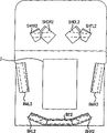
图7按照本发明第一实施例,画出扫描图案SVR,SVL的分解图,这些图案组成条码读取器射出的侧面图案。FIG. 7 shows an exploded view of scanning patterns SVR, SVL, which constitute side patterns emitted by a barcode reader, according to a first embodiment of the present invention.
图8按照本发明第一实施例,画出扫描图案SHTR,SHTL,SHDR和SHDL的分解图,这些图案组成条码读取器射出的侧面图案。Fig. 8 shows an exploded view of scanning patterns SHTR, SHTL, SHDR and SHDL, which constitute the side patterns emitted by the barcode reader, according to the first embodiment of the present invention.
图9按照本发明第一实施例,画出条码读取器的一个内部侧视图,表明专用图案反射镜的安排。Fig. 9 shows an internal side view of a bar code reader showing the arrangement of special pattern mirrors according to the first embodiment of the present invention.
图10按照本发明第一实施例,画出条码读取器的一个内部正视图,表明专用图案反射镜的安排。Fig. 10 shows an internal front view of a bar code reader showing the arrangement of special pattern mirrors according to the first embodiment of the present invention.
图11按照本发明第一实施例,画出条码读取器的一个内部顶视图,表明专用图案反射镜的安排。Fig. 11 shows an internal top view of a bar code reader showing the arrangement of special pattern mirrors according to the first embodiment of the present invention.
图12按照本发明第一实施例,画出条码读取器的一个内部顶视图,表明专用图案反射镜的安排。Fig. 12 shows an internal top view of a bar code reader showing the arrangement of special pattern mirrors according to the first embodiment of the present invention.
图13按照本发明的实施例,画出当条码垂直于底窗时的读取过程。Fig. 13 shows the reading process when the barcode is perpendicular to the bottom window according to an embodiment of the present invention.
图14A-14D按照本发明的实施例,画出在图13所示的读取过程中,条码与扫描条码的扫描图案之间的各种关系。14A-14D illustrate various relationships between barcodes and scanning patterns for scanning barcodes during the reading process shown in FIG. 13 according to an embodiment of the present invention.
图15按照本发明的实施例,画出当条码平行于底窗时的读取过程。Fig. 15 shows the reading process when the barcode is parallel to the bottom window according to an embodiment of the present invention.
图16A-16D按照本发明的实施例,画出在图15所示的读取过程中,条码与扫描条码的扫描图案之间的各种关系。16A-16D illustrate various relationships between barcodes and scanning patterns for scanning barcodes during the reading process shown in FIG. 15, according to an embodiment of the present invention.
图17是按照本发明第二实施例的一种条码读取器的内部侧视图。Fig. 17 is an internal side view of a bar code reader according to a second embodiment of the present invention.
图18是按照本发明第二实施例的一种条码读取器的内部顶视图。Fig. 18 is an internal top view of a bar code reader according to a second embodiment of the present invention.
图19是按照本发明第二实施例的一种条码读取器的内部正视图。Fig. 19 is an internal front view of a bar code reader according to a second embodiment of the present invention.
图20A按照本发明第二实施例,画出从条码读取器射出的底部图案的示意图。FIG. 20A is a schematic diagram illustrating a bottom pattern emitted from a barcode reader according to a second embodiment of the present invention.
图20B按照本发明第二实施例,画出从条码读取器射出的侧面图案的示意图。FIG. 20B is a schematic diagram illustrating side patterns emitted from a barcode reader according to a second embodiment of the present invention.
图21按照本发明第一实施例,画出扫描图案BMR,BML,BVR和BVL的分解图,这些图案组成条码读取器射出的底部图案。Fig. 21 shows an exploded view of scanning patterns BMR, BML, BVR and BVL, which constitute the bottom pattern emitted by the barcode reader, according to the first embodiment of the present invention.
图22按照本发明第二实施例,画出扫描图案BCR,BCL,BOR和BOL的分解图,这些图案组成条码读取器射出的底部图案。Fig. 22 shows an exploded view of scanning patterns BCR, BCL, BOR and BOL, which constitute the bottom pattern emitted by the barcode reader, according to the second embodiment of the present invention.
图23按照本发明第二实施例,画出扫描图案SVR,SVL的分解图,这些图案组成条码读取器射出的侧面图案。Fig. 23 shows an exploded view of scanning patterns SVR, SVL, which constitute side patterns emitted by a barcode reader, according to a second embodiment of the present invention.
图24按照本发明第二实施例,画出扫描图案SHTR,SHTL,SHDR和SHDL的分解图,这些图案组成条码读取器射出的侧面图案。Fig. 24 shows an exploded view of the scanning patterns SHTR, SHTL, SHDR and SHDL, which constitute the side patterns emitted by the barcode reader, according to the second embodiment of the present invention.
图25按照本发明第二实施例,画出条码读取器的一个内部侧视图,表明专用图案反射镜的安排。Fig. 25 shows an internal side view of a bar code reader showing the arrangement of dedicated pattern mirrors according to a second embodiment of the present invention.
图26按照本发明第二实施例,画出条码读取器的一个内部顶视图,表明专用图案反射镜的安排。Fig. 26 shows an internal top view of a bar code reader showing the arrangement of dedicated pattern mirrors according to a second embodiment of the present invention.
图27按照本发明第三个实施例,画出一种条码读取器的简图,表明从多面镜的不同方向入射的光束。Fig. 27 is a schematic diagram of a bar code reader according to a third embodiment of the present invention, showing beams incident from different directions of a polygon mirror.
现在详细参照本发明的优选实施例,这些实施例已在附图中画出,在所有附图中,用相同的参考数字表示相同的部件。Reference will now be made in detail to the preferred embodiments of the present invention, which are illustrated in the accompanying drawings, like reference numerals being used to refer to like parts throughout.
按照本发明的实施例,在下面说明的条码读取器(此后简称之为“装置”),最好是一个埋置在结帐柜台内的所谓多头扫描器。再有,装置的外侧结构,可以用当前流行的多种多头扫描器中任何一种的形式。因此,没有画出装置的外侧图形。According to an embodiment of the present invention, the barcode reader described below (hereinafter simply referred to as "device") is preferably a so-called multi-head scanner embedded in a checkout counter. Furthermore, the outer structure of the device can be in the form of any one of the currently popular multi-head scanners. Therefore, the outside figure of the device is not drawn.
如图1所示,装置包括一个底窗3,放在平行于结帐柜台2的一个表面(商品扫描表面),还包括一个侧窗14,最好与结帐柜台2的表面成直角地安放。由多束扫描光束组成的扫描图案,从各个窗3,14射出,以读取条码。条码读取器上安放底窗3的整个部分,此后被称为“底座部分”1;条码读取器上安放侧窗14的整个部分,此后被称为“侧面部分”4。As shown in Figure 1, the device comprises a
装置上固定底窗3的一个表面,要与结帐柜台2的表面处在同一水平上,这样,商品可以在结帐柜台2上滑动,同时读取条码。侧窗14也对着执行条码读取操作的操作员安放。A surface of the fixed
图1-3是按照本发明第一实施例的装置的一些内部视图。具体说,按照本发明第一实施例的条码读取装置,图1画出其内部侧视图,图2画出其内部顶视图,以及图3画出其内部正视图。图3A是侧窗14的一个正面剖面图,剖面取自侧窗14的一条伸延线附近。图3B是装置前端的正面剖面图。1-3 are some internal views of a device according to a first embodiment of the invention. Specifically, according to the bar code reading device of the first embodiment of the present invention, FIG. 1 shows its internal side view, FIG. 2 shows its internal top view, and FIG. 3 shows its internal front view. FIG. 3A is a front sectional view of the
如图1-3所示,装置包括一个底座部分1,它一般位于柜台2表面之下,还包括一个侧面部分4,它垂直于或近似垂直于柜台2的表面。底座部分1在其上的一个表面上有一个底窗3,它与柜台2的表面处于同一水平。底窗3与柜台2的表面处于同一水平,这样适合商品在柜台2表面上滑动,以读取条码。如果在柜台2表面与底座部分1的表面之间存在间隙,商品在间隙上可能被挡住,因而不利于读取过程,有时还会损坏商品。由于商品可以按前述方式滑过柜台2的表面,因此柜台2表面也被称为“商品滑动面”。还有,按照图1所示的本发明的实施例,底座部分1最好相对长一些,而侧面部分4则最好相对短一些。As shown in Figures 1-3, the device comprises a base portion 1, which is generally positioned below the surface of the
如图1所示,装置包括一个光源5,例如一个发射激光束的激光二极管;一个使光源5发射的激光束扫描的多面镜6,它是扫描装置的一个例子;一个由若干个反射镜组成的图案反射镜,用于产生扫描光束,通过适当地反射被多面镜6扫描的光束,便可以组成扫描图案,后面还要对图案反射镜作更详细的描述;一个光检测器8,它接收条码反射回来的光并输出与接收的光的强弱一致的电信号;一个模数转换电路9(后面称之为“A/D电路”,或简单地称为“基板”),它把光检测器8输出的信号(模拟信号)二进制化;最后还包括一块主印刷基板10(主PCB),其上有一个解码器,它根据A/D电路9输出的数字信号,把条码解调。到达光检测器8的反射光被一个凹面反射镜11所会聚并反射。As shown in Figure 1, the device includes a
在图1所示的本发明的实施例中,光源5使用激光二极管。光源5最好是一个激光光源组件,包含有一个准直器(未画出)和一个光阑(未画出),这些都是激光束的再成形装置,以便把激光二极管发射的激光束重新成形,还有一个驱动激光光源5的驱动电路(未画出),激光束再成形装置和驱动电路最好形成一个整体件。In the embodiment of the present invention shown in FIG. 1, the
光源5安装在图1所示装置的左侧部分的下部,即,侧面部分4的壳体的偏下部分。在装置下部的光源5,向上发射激光束。按照本发明的第一实施例,如图1所示,激光从光源5几乎竖直地向上发射。但是,从光源5发射激光的方向(即出射角)也可以有各种倾角,这将视装置的设计和其它条件而定。The
现有技术的多头扫描器,如前述本发明的第一实施例那样,以相同方式安装在结帐柜台上,它没有那种不把光束分束而能向上发射光束的结构。The prior art multi-head scanner, which is installed on the checkout counter in the same manner as the aforementioned first embodiment of the present invention, does not have the structure to project the beam upward without splitting the beam.
从光源5发射的激光,到达多面镜6。按照本发明的第一实施例,多面镜6位于侧面部分4壳体的中心附近。虽然在图上没有特别画出,按照本发明的第一实施例,多面镜最好包括四个反射面,每一个有略为不同的倾斜度。因为四个反射面的各个倾斜度都不同,多面镜6能够产生四束平行的扫描光。Laser light emitted from
用一个电机12驱动多面镜6旋转,使入射的激光扫描。电机12包括一个旋转轴12a。多面镜6的底座部分用模铸树脂制成,其上有一个孔。电机12的旋转轴12a插进多面镜6的基座部分的孔内。多面镜6有一旋转轴6a,它近似与底窗3平行地放置,底窗3基本上与商品滑动面是同一个。按照本发明的第一实施例,旋转轴6a最好相对于水平近似成5°,旋转轴6a的一侧更接近面朝下的底窗3。但是,多面镜6的旋转轴6a的倾斜度,只要合适,可以根据设计改变。A
因此,按照本发明的第一实施例,多面镜6可以有这样的构造,它使激光束从装置的底座部分向上到达多面镜6,并且扫描光被反射又从多面镜6向下出射。结果,多面镜6的反射面可以想象成是向下的。虽然还有些反射面是向上的,但因为一束激光束不可能同时发射到所有反射面,所以这些向上的面不是用来反射入射的激光的。如果只考虑那些有效地工作的反射面,那么可以认为反射面是向下的。此外,应该指出,可以用一个振镜取代一个多面镜来反射激光。Therefore, according to the first embodiment of the present invention, the
本发明的第一实施例,起码在下面几点上,与现有技术的多头扫描器不同,且优于现有技术的多头扫描器。现有技术的多头扫描器,多面镜的旋转轴是几乎垂直于底窗安装的。还有,现有技术的多面镜基本上安装在底座部分壳体内或侧面部分壳体之下。因此,在现有技术的光学扫描器的底座部分之内,不受约束地安装光学部件的空间就很有限了。再者,在现有技术的多头扫描器中,由于多面镜和光源的安装问题或由于激光的光路问题,在其底座部分之内,要增加图案反射镜的尺寸是特别困难的。The first embodiment of the present invention is different from and superior to prior art multi-head scanners at least in the following points. In prior art multi-head scanners, the rotation axis of the polygon mirror is installed almost perpendicular to the bottom window. Also, the prior art polygon mirror is basically installed in the base part casing or under the side part casing. Therefore, within the base portion of prior art optical scanners, there is limited space for unrestricted mounting of optical components. Furthermore, in the prior art multi-head scanner, it is particularly difficult to increase the size of the pattern mirror within its base portion due to the installation of the polygon mirror and the light source or due to the optical path of the laser light.
按照本发明的第一实施例,对光源5和扫描装置的安排是,在底座部分1的壳体内部既不安装光源5,也不安装扫描装置。这种安排的结果是,在底座部分1的壳体内部,其它光学部件,特别是图案反射镜的布置,就更加方便。According to the first embodiment of the invention, the arrangement of the
从条码反射的光是发散光。接收从条码反射的光,只要可能,都应增强,以便提高条码的读取性能。图案反射镜的功能是把条码的反射光送至光检测器8。因此,图案反射镜应该做得尽可能大。按照本发明的第一实施例的装置,能满足这些要求。The light reflected from the barcode is divergent light. The reception of light reflected from the barcode should be enhanced whenever possible in order to improve barcode reading performance. The function of the pattern mirror is to send the reflected light of the barcode to the
从图1可以看到,光检测器8附着在装有A/D电路9的基板上,所以光检测器8与基板9构成一块集成片。基板9固定在侧面部分4壳体后面附近,其位置近似平行于侧面部分4的壁面。如图1所示,光检测器8的光接收表面是朝下的。经凹面反射镜11会聚的光到达光检测器8的光接收表面。It can be seen from FIG. 1 that the
凹面反射镜11会聚信号光,并安装在从光源5到多面镜6的光路的中部。凹面反射镜11的反射面向着光检测器8,其作用是会聚条码的反射光(信号光),这些反射光经过多面镜6到达光检测器8。在凹面反射镜11的中央开有一个孔,它让光源5发射的激光到达多面镜6。The
主PCB 10位于侧面部分4壳体的底面上。主PCB 10上装有一个解码装置(未画出),一个把解码信号传送到POS终端及其它外部装置的接口连接器13,以及一个电压变换装置(未画出),它把从外部经一个AC插头(未画出)之类送来的电源电压变换成装置适用的电压。主PCB 10控制着光源5的发光,多面镜6的驱动,电机12,和A/D电路9的运行。The
从光源5投射出的激光束,经过一个准直透镜和一个光阑重新成形,具备了读取条码所要求的分辨能力,然后通过凹面反射镜11中央的孔,到达多面镜6。The laser beam projected from the
如上所述,多面镜6的四个反射面有不同的倾斜度,所以多面镜6产生四束平行的扫描光。来自多面镜6的扫描光向下投射,如图1所示。As mentioned above, the four reflective surfaces of the
多面镜6产生的扫描光被适当地分开,又经图案反射镜反射,图案反射镜的作用如同一种扫描线分离装置,它被安装在底座部分1和侧面部分4上,扫描光作为扫描图案从底窗3和侧窗14射出出去。扫描图案由多根沿不同方向扫描的扫描线组成。各个扫描线的扫描方向和角度由图案反射镜的倾斜度决定。The scanning light generated by the
图4A到图8画出从底窗3输出的扫描图案(底部图案)的图形和从侧窗4输出的扫描图案(侧面图案)的图形。再具体说,图4A是底部图案,图4B是侧面图案在相应的窗表面的图形。在图4A和图4B,包围扫描图案的矩形部分是窗的边框。图5和图6是组成底部图案的扫描图案图形;图7和图8是组成侧面图案的扫描图案图形,这些扫描图案已分别被分解。FIGS. 4A to 8 show graphs of scanning patterns output from the bottom window 3 (bottom pattern) and graphs of scanning patterns output from the side windows 4 (side patterns). More specifically, FIG. 4A is a bottom pattern, and FIG. 4B is a side pattern on a corresponding window surface. In Figures 4A and 4B, the rectangular portion surrounding the scan pattern is the border of the window. Fig. 5 and Fig. 6 are scanning pattern diagrams constituting the bottom pattern; Fig. 7 and Fig. 8 are scanning pattern diagrams constituting the side pattern, and these scanning patterns have been decomposed respectively.
现在参照图4-图8,对底部图案和侧面图案说明于后。从底窗3输出的扫描图案(底部图案)由下述八(8)种图案BMR,BML,BVR,BVL,BCR,BCL,BOR,BOL所组成。此外,每一种扫描图案最好由四条平行扫描线组成。但是,构成扫描图案的线不一定由完全平行的扫描线组成,虽然这里认为它们是平行的,同样的说明对本文全部成立。Referring now to FIGS. 4-8 , the bottom pattern and the side pattern will be described later. The scan pattern (bottom pattern) output from the
图4A画出在底窗3上的整个底部图案。图5和图6画出组成底部图案的不同扫描图案的分解图形。更具体说,图5画出扫描图案BML,BMR,BVL,BVR。图6画出扫描图案BCL,BCR,BOL,BOR。还有,图4A的上部靠近侧窗14的一侧。在图5和图6中的箭头,指明在一平坦表面上每一组扫描图案的一般的往外离去方向。FIG. 4A depicts the entire bottom pattern on the
在图5和图6所示图案中,BVR和BVL各自的扫描方向,最好近似垂直于底窗3的表面。其它扫描图案的扫描方向最好近似平行于底窗3表面。但是,扫描图案的扫描方向不限制在完全垂直/水平方向,扫描方向也可以略微偏离垂直和水平方向。无论如何,为便于本发明的讨论,两个扫描方向都可以认为是垂直/水平的。还有,扫描图案的扫描方向并不限于图中所画的方向,只要适当,也可以改变。In the patterns shown in FIGS. 5 and 6 , the respective scanning directions of BVR and BVL are preferably approximately perpendicular to the surface of the
特别如在图6所见,对照一对扫描图案BOR和BOL,严格地说,扫描图案BOR和BOL不是完全左右对称的。对BOR和BOL而言,在左边和右边的扫描位置,是通过故意移动或调整扫描图案而形成的,以便增加条码的读取(扫描)概率。In particular, as seen in FIG. 6, in contrast to a pair of scanning patterns BOR and BOL, strictly speaking, the scanning patterns BOR and BOL are not completely left-right symmetric. For BOR and BOL, the scanning positions on the left and right are formed by deliberately moving or adjusting the scanning pattern in order to increase the probability of reading (scanning) the barcode.
如图4B,图7和图8所示,从侧窗14输出的扫描图案(侧面图案)由下述六种扫描图案SVR,SVL,SHTR,SHTL,SHDR,SHDL所组成。这六种扫描图案都由四根平行扫描线组成。As shown in FIG. 4B, FIG. 7 and FIG. 8, the scan pattern (side pattern) output from the
按照本发明的第一实施例,图4B是侧窗14表面上的侧面图案的整个图形。图7和图8画出组成侧面图案的每一种扫描图案的分解图。与图5和图6所画扫描图案类似,图7和图8中的箭头,指明在一平面表面上每一种扫描图案的往外离去方向。FIG. 4B is an overall diagram of the side pattern on the surface of the
在图7和图8所示六种扫描图案中,SVR和SVL沿近似垂直于底窗3表面的方向扫描。其它扫描图案SHTR,SHTL,SHDR,和SHDL则沿近似平行于底窗3表面的方向扫描。此外,于图5和图6的扫描方向类似,真正的扫描方向不是完全垂直或水平的,而是略略倾斜,这在图8可以看出。不过,按照本发明的实施例,可以认为扫描图案是沿垂直/水平方向扫描的。Among the six scanning patterns shown in FIGS. 7 and 8 , SVR and SVL scan along a direction approximately perpendicular to the surface of the
组成底部图案(图4A)和侧面图案(图4B)的扫描线,其往外离去路径现说明于后。The scan lines constituting the bottom pattern (FIG. 4A) and the side pattern (FIG. 4B) and their outgoing paths are described later.
虽然激光是从光源5向着多面镜6发射的,但所有扫描线的路径都共同汇集到这一点。然后,从多面镜6发出的扫描光按下述顺序扫描图案反射镜:SVL1-SHR1-BMR1-BVR1-BZ1-BVL1-BML1-SHL1-SVR1。另外,图案反射镜画在图4至图6内。Although the laser light is emitted from the
附在图案反射镜上的符号的第一个字母,表示该图案反射镜是与底部图案对应还是与侧面图案对应。以字母B开始的图案反射镜与底部图案相对应,而字母S开始的图案反射镜与侧面图案相对应。还有,关于图案反射镜的符号,字母V表示有关的扫描图案是沿垂直方向扫描的;字母H表示有关的扫描图案是沿水平方向扫描的;字母L表示有关的扫描图案是从扫描器的左侧射出的;字母R表示有关的扫描图案是从扫描器的右侧射出的;字母T表示有关的扫描图案是从侧窗的顶侧(上部)射出的;和字母D表示有关的扫描图案是从侧窗的底侧(下部)射出的。字母Z和M则没有任何特定含义。The first letter of the symbol attached to the gobo mirror indicates whether the gobo mirror corresponds to the bottom or side pattern. Pattern mirrors beginning with the letter B correspond to the bottom pattern, while pattern mirrors beginning with the letter S correspond to the side patterns. Also, regarding the symbol of the pattern mirror, the letter V indicates that the relevant scanning pattern is scanned along the vertical direction; the letter H indicates that the relevant scanning pattern is scanned along the horizontal direction; the letter L indicates that the relevant scanning pattern is scanned from the scanner The letter R indicates that the associated scan pattern is emitted from the right side of the scanner; the letter T indicates that the associated scan pattern is emitted from the top side (upper part) of the side window; and the letter D indicates the associated scan pattern It is shot from the bottom side (lower part) of the side window. The letters Z and M do not have any specific meaning.
图案反射镜的反射面是朝向多面镜6的,并排列成扇形。与底部图案对应的图案反射镜把来自多面镜6的扫描光向底座部分1反射,而与侧面图案对应的图案反射镜把来自多面镜6的扫描光向侧面部分4反射,The reflective surfaces of the pattern mirrors face the
产生底部图案的底部图案反射镜安装在装置的底座部分,它由下述反射镜组成。The bottom pattern mirror for generating the bottom pattern is mounted on the base portion of the device, which consists of the following mirrors.
BZ1,BVR1,BVL1,BMR1,BML1,BMR2,BML2,BMR3,MBL3,BMR4,BML4,BHR2,BHL2,BZ2,BZR3,BZL3。BZ1, BVR1, BVL1, BMR1, BML1, BMR2, BML2, BMR3, MBL3, BMR4, BML4, BHR2, BHL2, BZ2, BZR3, BZL3.
这些反射镜近似地对称于装置中心线安装。其中,五个反射镜BZ1,BVR1,BVL1,BMR1和BML1安装在侧面部分4的底座上,并且它们的反射面向着底座部分1。四个反射镜BZR3,BZL3,BMR4,BML4安装在底座部分1的底面上。七个反射镜BMR2,BML2「BMR3,BML3,BHR2,BHL2,和BZ2的各个反射面都略微向下倾斜,并安装在底座部分1的侧壁上。These mirrors are mounted approximately symmetrically about the centerline of the device. Among them, five reflectors BZ1 , BVR1 , BVL1 , BMR1 and BML1 are installed on the base of the side part 4 , and their reflective surfaces face the base part 1 . Four mirrors BZR3 , BZL3 , BMR4 , BML4 are mounted on the bottom surface of the base part 1 . Each of the seven mirrors BMR2, BML2, BMR3, BML3, BHR2, BHL2, and BZ2 has a slightly downward slope and is mounted on the side wall of the base part 1.
还有,反射镜BZR3和BZL3的外侧部分各自稍稍向上倾斜,如图3所画。通过把反射镜BZR3和BZL3向上倾斜,能够确保在底座部分1的底座和图案反射镜(如BZL3)之间有一间隙。电缆之类可以适当地放在底座部分1的底座和图案反射镜之间的间隙内(在图3内,此电缆是一个黑色圆圈)。图案反射镜BMR4和BML4也和图案反射镜BZR3和BZL3一样,作同样的倾斜。Also, the outer portions of the mirrors BZR3 and BZL3 are each slightly inclined upward as shown in FIG. 3 . By tilting the mirrors BZR3 and BZL3 upward, it is possible to ensure a gap between the base of the base portion 1 and the pattern mirror such as BZL3. A cable or the like can be properly placed in the gap between the base of the base part 1 and the pattern mirror (in FIG. 3, this cable is a black circle). The pattern mirrors BMR4 and BML4 are also tilted in the same manner as the pattern mirrors BZR3 and BZL3.
组成底部图案的扫描线首先被多面镜6反射,然后经过下述路径传播之后,从底窗射出。The scanning lines constituting the bottom pattern are firstly reflected by the
BMR:多面镜-BMR1-BMR2-BMR3-BMR4-底窗BMR: Polygon Mirror-BMR1-BMR2-BMR3-BMR4-Bottom Window
BML:多面镜-BML1-BML2-BML3-BML4-底窗BML: Polygon Mirror-BML1-BML2-BML3-BML4-Bottom Window
BCR:多面镜-BZ1-BZ2-BZR3-底窗BCR: Polygon Mirror-BZ1-BZ2-BZR3-Bottom Window
BCL:多面镜-BZ1-BZ2-BZL3-底窗BCL: polygonal mirror-BZ1-BZ2-BZL3-bottom window
BOR:多面镜-BZ1-BHR2-BZR3-底窗BOR: Polygon Mirror-BZ1-BHR2-BZR3-Bottom Window
BOL:多面镜-BZ1-BHL2-BZL3-底窗BOL: Polygon Mirror-BZ1-BHL2-BZL3-Bottom Window
BVR:多面镜-BVR1-BHR2-BZR3-底窗BVR: Polygon Mirror-BVR1-BHR2-BZR3-Bottom Window
BVL:多面镜-BVL1-BHL2-BZL3-底窗BVL: Polygon Mirror-BVL1-BHL2-BZL3-Bottom Window
由上可知,路径BCR(BCL)和BOR(BOL)使用相同的两个图案反射镜BZ1和BZR3(BZL3),它们之间的差别仅是BZ2和BHR2(BHL2)那部分路径。类似地,路径BOR(BOL)和BVR(BVL)两者都使用相同的两个图案反射镜BHR2(BHL2)和BZR3(BZL3),所以BZ1和BVR1(BVL1)是不同的,它们是经由多面镜6扫描的扫描光首先入射的图案反射镜。It can be known from the above that the paths BCR (BCL) and BOR (BOL) use the same two patterned mirrors BZ1 and BZR3 (BZL3 ), and the difference between them is only the part of the paths of BZ2 and BHR2 (BHL2 ). Similarly, paths BOR(BOL) and BVR(BVL) both use the same two patterned mirrors BHR2(BHL2) and BZR3(BZL3), so BZ1 and BVR1(BVL1) are different, they are 6 Scanning The scanning light is first incident on the pattern mirror.
因此,虽然不同的扫描线共同使用两个图案反射镜,但采用上述结构,底座部分1内必须容纳的图案反射镜的数目可以减少。因而,按照本发明,由于减少了图案反射镜的总数,假如在相同的空间内安放这些反射镜,每一个反射镜的面积就能够增大,同时,由条码反射的光的会聚效率就能够提高。Therefore, although different scanning lines commonly use two pattern mirrors, with the above structure, the number of pattern mirrors that must be accommodated in the base portion 1 can be reduced. Therefore, according to the present invention, since the total number of pattern mirrors is reduced, if these mirrors are placed in the same space, the area of each mirror can be increased, and at the same time, the converging efficiency of the light reflected by the bar code can be improved. .
虽然由路径BOR(BOL)和BVR(BVL)形成的图案,专门描绘出其扫描轨迹,但在本发明之前,还没有一个装置,其中扫描轨迹完全不同的扫描线,是按上述本发明那种方式,从一个共用的扫描反射镜所反射的。Although the patterns formed by the paths BOR (BOL) and BVR (BVL) specifically delineate their scan trajectories, prior to the present invention there has been no device in which the scan lines of completely different scan trajectories are of the type described in the above-mentioned invention. way, reflected from a common scanning mirror.
产生侧面图案的侧面图案反射镜,由下面的反射镜组成:SVR1,SVL1,SVR2,SVL2,SHR1,SHL1,SHTR2,SHTL2,SHTR3,SHTL3,SHDR2,SHDL2,SHDR3,SHDL3。Side pattern mirrors that generate side patterns, consisting of the following mirrors: SVR1, SVL1, SVR2, SVL2, SHR1, SHL1, SHTR2, SHTL2, SHTR3, SHTL3, SHDR2, SHDL2, SHDR3, SHDL3.
产生侧面图案的图案反射镜,按与底座图案反射镜相同的方式,近似地对称于装置中心线安装。还有,四个图案反射镜SHTR2,SHTL2,SHDR2,SHDL2的安装,要使各个反射侧都朝下。The patterned mirrors that create the side patterns are mounted approximately symmetrically about the centerline of the device in the same manner as the base patterned mirrors. Also, the four pattern reflectors SHTR2, SHTL2, SHDR2, and SHDL2 are installed so that each reflective side faces downward.
组成侧面图案的各个扫描图案,首先被多面镜6扫描,然后经过下述路径传播之后,从侧窗14射出。Each scanning pattern constituting the side pattern is first scanned by the
SVR:多面镜-SVR1-SVR2-侧窗SVR: Polygon Mirror-SVR1-SVR2-Side Windows
SVL:多面镜-SVR1-SVR2-侧窗SVL: Polygon mirror-SVR1-SVR2-side window
SHTR:多面镜-SHR1-SHTR2-SHTR3-侧窗SHTR: Polygon mirror-SHR1-SHTR2-SHTR3-side window
SHTL:多面镜-SHL1-SHTL2-SHTL3-侧窗SHTL: Polygon mirror-SHL1-SHTL2-SHTL3-side window
SHDR:多面镜-SHR1-SHDR2-SHDR3-侧窗SHDR: Polygon mirror-SHR1-SHDR2-SHDR3-side window
SHDL:多面镜-SHL1-SHDL2-SHDL3-侧窗SHDL: Polygon mirror-SHL1-SHDL2-SHDL3-side window
从上面可以看出,SHR1(SHL1)被作为SHTR(SHTL)和SHDR(SHDL)的共用反射镜而使用。As can be seen from the above, SHR1 (SHL1) is used as a common mirror for SHTR (SHTL) and SHDR (SHDL).
图9按照本发明第一实施例,画出条码读取器的一个内部侧视图,表明专用图案反射镜的安装位置。在每一个图案反射镜内的直线表示扫描线在每一个图案反射镜内的扫描轨迹。这里画出四条平行扫描线中最靠外的两条。还有,在图内画在BML3上的两条扫描线,虽然不是严格平行,但对所有的目的和用途来说,可以认为是“平行”的。如图9所示,可以看出,在图9的图案反射镜中,BHR2被两种类型扫描线所扫描,这两类扫描线几乎垂直于近似水平的平面。Fig. 9 shows an internal side view of the barcode reader showing the installation position of the special pattern mirror according to the first embodiment of the present invention. The straight line in each pattern mirror represents the scanning trajectory of the scan line in each pattern mirror. Here the outermost two of the four parallel scan lines are drawn. Also, the two scan lines drawn on the BML3 in the figure, although not strictly parallel, can be considered "parallel" for all purposes and uses. As shown in FIG. 9, it can be seen that, in the patterned mirror of FIG. 9, BHR2 is scanned by two types of scanning lines, which are almost perpendicular to an approximately horizontal plane.
图10按照本发明第一实施例,画出条码读取器的一个内部正视图,表明专用图案反射镜的安装位置。更具体说,图10只画出一个专用图案反射镜,明确地说,是装在侧面部分4的壳体内的图案反射镜。此外,图案反射镜SVR2没有在图上画出,它与图案反射镜SVL2构成一对。扫描线的轨迹以实线描绘在图10的图案反射镜内。Fig. 10 shows an internal front view of a barcode reader showing the installation position of a dedicated pattern mirror according to the first embodiment of the present invention. More specifically, FIG. 10 only shows a dedicated gobo mirror, specifically, the gobo mirror housed in the housing of the side part 4. As shown in FIG. In addition, the pattern mirror SVR2 is not shown in the figure, and it forms a pair with the pattern mirror SVL2. The traces of the scan lines are depicted in solid lines within the patterned mirror of FIG. 10 .
图11和图12按照本发明第一实施例,画出条码读取器的一个内部顶视图,表明专用图案反射镜的安装位置。更具体说,图11画出反射面朝上的各个图案反射镜,而图12画出反射面朝下的各个图案反射镜。11 and 12 show an internal top view of the barcode reader showing the installation position of the special pattern mirror according to the first embodiment of the present invention. More specifically, FIG. 11 shows the respective pattern mirrors with the reflective surface facing upward, and FIG. 12 shows the respective pattern mirrors with the reflective surface downward.
如图11所示,BZL3和BZR3被总数为三条并互相交叉的扫描线所扫描,而BML4和BMR4也被三种扫描线扫描,这些扫描线互相交叉,构成一个直角。As shown in FIG. 11, BZL3 and BZR3 are scanned by a total of three scanning lines intersecting each other, while BML4 and BMR4 are also scanned by three scanning lines intersecting each other to form a right angle.
在图12中,由于图案反射镜的反射面是朝下的,所以扫描图案反射镜的扫描线轨迹用虚线表示。如图12所示,画在图12上的图案反射镜中,BHR2和BHL2被两种交叉的扫描线所扫描。In FIG. 12, since the reflective surface of the pattern mirror is directed downward, the trace of the scanning line for scanning the pattern mirror is indicated by a dotted line. As shown in FIG. 12, in the pattern mirror drawn on FIG. 12, BHR2 and BHL2 are scanned by two kinds of intersecting scanning lines.
图13是一个解释性示意图,它按照本发明的第一实施例,画出当条码垂直于底窗3时,在条码读取过程中扫描图案的扫描轨迹。在图13所示情形中,条码被几乎与条码方向一致的扫描图案所扫描,就是说,扫描图案向着条码发出,并且条码被沿垂直于底窗3的方向扫描。更具体说,这些图案是(1)图案SVR和SVL两者都从侧窗14发出,和(2)图案BVR和BVL两者都从底窗3发出。FIG. 13 is an explanatory diagram showing the scanning locus of the scanning pattern during barcode reading when the barcode is perpendicular to the
如图13所示,带有条码的商品对着侧窗14从装置的右侧移动到左侧。当条码如图13那样移动时,可以考虑四种情况:(1)条码近似对着侧窗14;(2)条码对着商品移动的方向;(3)条码对着商品移动的相反方向;和(4)条码对着操作员(不是对着侧窗14)。As shown in FIG. 13 , the barcoded merchandise moves from the right side of the device to the left side against the
图14A-14D按照本发明的实施例,对上述四种情况,画出条码与扫描条码的扫描图案之间的关系。14A-14D illustrate the relationship between the barcode and the scanning pattern for scanning the barcode for the above four situations according to the embodiment of the present invention.
更具体说,图14A画出条码对着侧窗14时的示意图。此时,条码被侧窗14射出的SVR图案和SVL图案扫描,然后被读取。More specifically, FIG. 14A shows a schematic diagram of the barcode facing the
图14B画出条码对着商品移动方向时的示意图。此时,条码被侧窗14射出的SVR图案扫描以及被底窗3射出的BVL图案扫描。FIG. 14B is a schematic diagram of the barcode facing the moving direction of the commodity. At this time, the barcode is scanned by the SVR pattern emitted from the
图14C画出条码对着商品移动的相反方向时的示意图。此时,条码被侧窗14射出的SVL图案扫描以及被底窗3射出的BVR图案扫描。Figure 14C shows a schematic view of the barcode moving in the opposite direction against the merchandise. At this time, the barcode is scanned by the SVL pattern emitted from the
图14D画出条码对着操作员时的示意图。此时,条码没有被侧窗14射出的扫描线扫描。不过,条码被向着侧窗14射出的BVR图案和BVL图案扫描,并被读取。Figure 14D depicts a schematic view of the barcode facing the operator. At this time, the bar code is not scanned by the scan lines emitted from the
因此,如图14A-14D所示,不论条码向着什么方向,条码的360°读取变成可能了。Therefore, as shown in FIGS. 14A-14D , no matter what direction the barcode faces, 360° reading of the barcode becomes possible.
图15是一个解释性示意图,它按照本发明的实施例,画出当条码处在平行于底窗3的位置时,条码的读取过程,并且表明当条码几乎平行于底窗3时,扫描图案扫描时的扫描轨迹。在图15,条码是用平行于底窗3方向扫描的扫描图案来扫描。此外,商品的移动方向与图13情况相同,具体说,商品对着侧窗14从装置的右侧移动到左侧。Fig. 15 is an explanatory diagram, it according to the embodiment of the present invention, draws when the barcode is in the position parallel to the
在图15所示的情形下,可以考虑四种情况:(1)条码对着侧窗14;(2)条码对着商品移动的方向;(3)条码对着商品移动的相反方向;和(4)条码对着操作员。In the situation shown in Figure 15, four situations can be considered: (1) the barcode is facing the
按照本发明的实施例,图16A-16D画出上述四种情况下,条码与扫描条码的扫描图案之间的关系。According to an embodiment of the present invention, FIGS. 16A-16D illustrate the relationship between the barcode and the scanning pattern for scanning the barcode in the above four cases.
更具体说,图16A画出条码对着侧窗14的情况。此时,条码被侧窗14射出的SHTR图案,SHTL图案或SHDL图案扫描。此外,在图16A所示情形中SHTR和SHDR,SHTL和SHDL,实际上描绘出相同的扫描轨迹,在图上不表示成分开的形式。More specifically, FIG. 16A depicts the barcode facing
图16B画出条码对着商品移动方向的情况。此时,条码被向着商品移动方向的底窗3射出的BML图案扫描。以及被底窗3射出的BVL图案扫描。Figure 16B depicts the barcode against the direction of merchandise movement. At this time, the barcode is scanned by the BML pattern emitted from the
图16C画出条码对着商品移动的相反方向的情况。此时,条码被底窗3射出的BMR图案扫描。Figure 16C depicts the case where the barcode is moving in the opposite direction against the merchandise. At this time, the barcode is scanned by the BMR pattern emitted from the
图16D画出条码对着操作员的情况。此时,条码没有被侧窗14射出的扫描线扫描。不过,条码被从底窗3向着侧窗14射出的BOR,BCR,BCL和BOL每一种图案扫描。Figure 16D depicts the barcode facing the operator. At this time, the bar code is not scanned by the scan lines emitted from the
因此,按照本发明,360°读取变成可能了,即使条码被置于与底窗14平行的位置。Therefore, according to the present invention, 360° reading becomes possible even if the bar code is placed in parallel with the
在图14与图16中,描绘出几乎垂直于底窗14的扫描轨迹的BVR(BVL)图案,和描绘出几乎平行于底窗14的扫描轨迹的BOR(BOL)图案,分别以近似相同的方向从底窗14射出。换言之,虽然这些扫描图案描绘出不同的扫描轨迹,但它们能在实际相同的条件下扫描条码。因之,同一条码,即使该条码垂直于底窗14和即使该条码平行于底窗14,都能够被读取。In Fig. 14 and Fig. 16, describe the BVR (BVL) pattern that is almost perpendicular to the scanning track of
因此,即使条码处在垂直于底窗14的位置和即使条码处在平行于底窗14的位置,按照本发明的优选实施例,都给出完全360°的读取。把底座扫描器部分1做得比现有技术的多头扫描器更薄,也是可能的。具体说,底座扫描器部分1的厚度可以做成90mm或更小。Therefore, even if the bar code is in a position perpendicular to the
因此,按照本发明的优选实施例,在读取区域,扫描一个实际上平的,近似与侧窗3平行的平面的扫描线,可以从底座扫描部分1产生。这一点是可以达到的,因为按照本发明的优选实施例,多面镜6是安装在侧面部分4的壳体的上部,且在底座部分1的壳体内部,用来产生部分水平扫描线的反射镜是共用的。因而,在底座部分1的空间被充分利用。更具体说,按照本发明的优选实施例,组成水平图案和垂直图案的两种或多种扫描图案,在从多面镜6伸延至读取开口(窗)的光路中,共用相同的两个图案反射镜。这种结构的条码读取器,在现有技术中是没有的。Therefore, according to a preferred embodiment of the present invention, a scanning line that scans a substantially flat plane approximately parallel to the
按照优选实施例,加长从多面镜6至底座部分1壳体的距离,对用相同的扫描角来产生更长的扫描线这一点来说,是特别有效和有利的。还有,这种结构在底座部分1内保留一定空间,从而有可能增加图案反射镜的面积或增加所用图案反射镜的数目,所以这种结构也是极其有用的。According to the preferred embodiment, lengthening the distance from the
现有技术的条码读取器,其结构中用单一的激光束来产生扫描线,从多面镜到读取器窗的光路长度是短的,所以不可能得到足够长的扫描线。因此,用现有技术的条码读取器,不可能产生这样的扫描线,它能从底座部分垂直地扫描上述实际上平的表面。但是,如上面所指出,按照本发明的优选实施例,可以产生从底座部分1垂直地扫描实际上平的表面的扫描线。In prior art bar code readers, in which a single laser beam is used to generate scanning lines, the optical path length from the polygon mirror to the reader window is short, so it is impossible to obtain sufficiently long scanning lines. Therefore, with prior art bar code readers, it is not possible to generate a scan line which is able to scan the above-mentioned substantially flat surface perpendicularly from the base portion. However, as indicated above, according to a preferred embodiment of the present invention, scan lines can be generated which scan a substantially flat surface perpendicularly from the base portion 1 .
还有,在现有技术的条码读取器中,产生垂直地扫描实际上平的表面的扫描线的图案反射镜,不能确保容纳并把该图案反射镜安装在壳体之内的必要的空间。再有,由于现有技术的条码读取器,其光束是从单一方向到达现有技术的多面镜上,所以不能像本发明的优选实施例那样,产生垂直地扫描实际上平的表面的扫描线。Also, in prior art bar code readers, the pattern mirror that produces a scan line that scans a substantially flat surface vertically cannot secure the necessary space for accommodating and installing the pattern mirror within the housing. . Also, since prior art bar code readers have beams that strike prior art polygon mirrors from a single direction, they cannot produce scans that scan a substantially flat surface vertically as in the preferred embodiment of the present invention. Wire.
按照本发明的优选实施例,多面镜6有四个反射表面(小平面)。但是,多面镜6不限于四(4)个反射面,也可以有例如三(3)个反射面或五(5)个或更多个反射面。According to a preferred embodiment of the invention, the
当减少多面镜6的反射面的数目时,可以获得成比例增大的扫描角。例如,当多面镜6有四(4)个反射面时,扫描角能够达180°。另一方面,当多面镜6有三个反射面时,扫描角能够达240°。因此,如果扫描角优先,那么反射面越少,结果越好。在相同光路长度下进行比较,如果扫描角大,则产生的扫描图案能够成比例地增加扫描线的长度。When the number of reflecting surfaces of the
当多面镜6有较少的反射面时,单次扫描能够产生的扫描线的数目就减少。例如,当使用有三个反射面的多面镜6时,产生三条扫描线,而使用有四个反射面的多面镜6时,能够产生四条扫描线。When the
当增加扫描线的数目时,各个扫描线之间的间隔就成比例地变窄。反之,当减少扫描线的数目时,各个扫描线之间的间隔就变宽。在后一种情形,如果读取时遇到带有低反衬的所谓“截尾标记”,可能会出问题,例如在扫描线之间会丢失条码而不能全部读取。如果使扫描线之间的间隔变窄,以防止丢失扫描线之间的条码,那么,较少扫描线的扫描图案,其扫描范围变得更窄,从而不可能保证有足够的读取面积。When the number of scan lines is increased, the interval between the individual scan lines is proportionally narrowed. Conversely, when the number of scanning lines is reduced, the interval between the individual scanning lines becomes wider. In the latter case, problems can arise when reading so-called "truncated marks" with low contrast, such as missing barcodes between scan lines and not being able to read them all. If the interval between scan lines is narrowed to prevent missing barcodes between scan lines, then the scan range becomes narrower for scan patterns with fewer scan lines, making it impossible to ensure a sufficient reading area.
当使用有四个表面的多面镜6时,其扫描角小于有三个表面的多面镜6,于是,要得到相同长度的扫描线,就需要一条正比地增长的扫描线光路。按照本发明的优选实施例,多面镜6被放置在靠近侧面部分4壳体的顶部,所以能够增加多面镜6与底座部分1的距离,从而加长光路的长度。因此,按照本发明的优选实施例,即使采用小扫描角的一个四面的多面镜6,也能够得到扫描线长度足够长的扫描线。When a
当多面镜6的反射面数目增加至五个或更多时,扫描角更进一步减小。这时,如果得到的光路比用四个反射面的多面镜6的装置还长,才适合用这种多面镜6。When the number of reflecting surfaces of the
再有,按照上述本发明的优选实施例,只在底座部分1中采用共用两个图案反射镜的扫描图案。然而,共用两个图案反射镜的扫描图案也可以用侧面的图案反射镜。而且,还可以采用共用三个或更多图案反射镜的不同的扫描图案。Also, according to the above-described preferred embodiment of the present invention, only the scanning pattern of the two pattern mirrors is used in the base portion 1 . However, scanning patterns that share two pattern mirrors can also use side pattern mirrors. Also, different scanning patterns sharing three or more patterned mirrors can be used.
如图1-图3所示,按照本发明的优选实施例,装置包括一个扬声器15,它发出一种声音,表示条码是否已经读取,此扬声器安装在侧面部分4的顶部。As shown in FIGS. 1-3, according to a preferred embodiment of the present invention, the device includes a
现有技术的多头扫描器有若干个扬声器,安装在装置侧面靠底部处。然而,按照现有技术的装置,装置的侧面埋在柜台内,于是扬声器被柜台覆盖。结果,操作员难以确认指示条码是否已经读取的声音,所以现有技术的装置是有问题的。举例说,超级市场结帐柜台周围的区域颇为嘈杂,来自扬声器的音量必须高。因而,由于现有技术的扬声器被远远藏在柜台底下,它不可能发出足够大的音量。虽然可以增大扬声器的尺寸而增加扬声器的音量,但安装在多头扫描器上的现有技术的扬声器却不够大,所以,这种解决问题的方法没有多大效果。Prior art multi-head scanners have several loudspeakers mounted on the sides of the device near the bottom. However, according to prior art devices, the sides of the device are buried in the counter, so that the speakers are covered by the counter. As a result, it is difficult for the operator to confirm the sound indicating whether the barcode has been read, so the prior art device is problematic. For example, the area around the checkout counter in a supermarket is quite noisy and the volume from the speakers must be high. Thus, since the prior art loudspeaker is hidden far under the counter, it is impossible to produce a sufficient volume. Although it is possible to increase the volume of the speaker by increasing the size of the speaker, the prior art speakers mounted on the multi-head scanner are not large enough, so this solution to the problem is not very effective.
与之相比,因为按照本发明的优选实施例的扬声器是安放在侧面部分4壳体顶部的前面,哪怕是一个小直径的扬声器,也能向操作员发出足够高音量的声音,指示条码是否已经读取。而且,因为声音发射还有方向性,在考虑到声音的发射后,把扬声器安放在装置的前面而不是侧面,是有作用的。In contrast, because the speaker according to the preferred embodiment of the present invention is placed in front of the top of the housing of the side portion 4, even a small diameter speaker can sound loud enough to the operator to indicate whether the bar code is already read. Also, since sound emission is also directional, it makes sense to place the loudspeakers on the front of the unit rather than on the side after accounting for sound emission.
按照本发明的优选实施例,为什么扬声器能够安放在侧面部分4壳体顶部的前面,现在在下面给出解释。Why the loudspeaker can be placed in front of the top of the housing of the side part 4 according to the preferred embodiment of the present invention is now explained below.
在现有技术的多头扫描器中,无论是什么地方,只要有足够的空间,图案反射镜便安装在那里。例如,在现有技术的多头扫描器中,图案反射镜既安装在侧面部分壳体的顶部也安装在侧面部分壳体的侧面。按照现有技术,只要能够获得所需的读取能力,便优先考虑图案反射镜和其它光学部件的布局。在开放的空间内,当光学部件就位之后,才考虑安装不特别影响扬声器和读取本身的部件。因此,在现有技术的多头读取器中,扬声器被安放在装置壳体的侧面并在柜台之下。In the prior art multi-head scanner, wherever there is enough space, the pattern mirror is installed there. For example, in prior art multi-head scanners, the pattern mirror is mounted on both the top and the side of the side part housing. According to the prior art, the layout of patterned mirrors and other optical components is given priority as long as the required readability can be achieved. In open spaces, when the optics are in place, consider installing components that do not particularly interfere with the speakers and readout itself. Thus, in prior art multi-head readers, the speakers are placed on the side of the device housing and under the counter.
按照本发明的优选实施例,多面镜6安装在侧面部分4壳体的顶部,并且在装置内近似水平地安装旋转轴。因此,到达或离开多面镜6的光线的光路上不能安装光学部件,以免阻挡光路。从图2和图3可以看出,按照本发明的优选实施例,图案反射镜不安装在侧面部分4的中央,并且,更具体说,图案反射镜不放在靠近侧面部分4的顶部。According to a preferred embodiment of the present invention, the
按照本发明的优选实施例,扬声器安装在没有图案反射镜的空间内,靠近侧面部分4壳体的顶部。这是多面镜6按照本发明来安装的第二效果。这对使用蜂鸣器之类来取代扬声器的装置,同样适用。According to a preferred embodiment of the present invention, the loudspeaker is mounted in a space free of patterned mirrors, close to the top of the side part 4 housing. This is the second effect of the installation of the
按照本发明的优选实施例,当把扬声器安装在侧面部分4壳体的顶部时,在底座部分1内有更大的自由度来安排图案反射镜和其它光学部件。单凭这一点,多面镜6和其它扫描装置就不必平行于底座部分1的表面。更准确地说,如果扫描光是向下射出(反射)的,就有可能增大安排各种光学部件的空间。因此,依据多面镜6的形状,旋转轴也可以改变为垂直于底座部分1的表面。According to a preferred embodiment of the invention, when mounting the loudspeaker on top of the housing of the side part 4, there is greater freedom in the base part 1 to arrange the patterned mirror and other optical components. This alone makes it unnecessary for the
还有,如果单单考虑把扫描装置安排在侧面部分4壳体之内,那么扫描装置不一定安排在靠近侧面部分4壳体的顶端。例如,按照本发明的优选实施例,为了满足设计要求,不排斥把扫描装置安放在侧面部分4壳体的底部的可能性。当按照本发明的扫描装置,被安放在靠近侧面部分4壳体的底部时,有效的反射面朝上,并且扫描装置可以向上发出扫描光。Also, if the scanning device is only considered to be arranged in the housing of the side part 4, the scanning device is not necessarily arranged near the top of the housing of the side part 4. For example, according to the preferred embodiment of the present invention, in order to meet the design requirements, the possibility of placing the scanning device at the bottom of the casing of the side part 4 is not excluded. When the scanning device according to the present invention is placed near the bottom of the housing of the side part 4, the effective reflective surface faces upwards, and the scanning device can emit scanning light upwards.
按照本发明的实施例,可以用其它类型的扫描装置,例如电流计式反射镜和振镜。此外,衍射栅圆盘也可以与反射镜一起使用。衍射栅可以是反射式的或透过式的。Other types of scanning devices may be used in accordance with embodiments of the present invention, such as galvano mirrors and galvanometer mirrors. In addition, diffraction grating disks can also be used with mirrors. Diffraction gratings can be reflective or transmissive.
如果这些因素都考虑到,那么来自光源的光束就不必垂直于底座部分1的表面发射。按照本发明的优选实施例,对图案反射镜的安排而外言,不必考虑光束垂直于底座部分1的表面向上发射。无论如何,光束不必垂直于底座部分1的表面发射,而且只要图案反射镜的安排不发生问题,光束可以从侧面入射。If these factors are taken into account, the light beam from the light source need not be emitted perpendicular to the surface of the base part 1 . According to the preferred embodiment of the present invention, it is not necessary for the arrangement of the patterned mirrors to consider that the light beam is emitted upwards perpendicularly to the surface of the base part 1 . In any case, the light beam does not have to be emitted perpendicular to the surface of the base portion 1, and the light beam may be incident from the side as long as no problem occurs with the arrangement of the patterned mirror.
图17-图19是按照本发明的第二实施例,画出一种条码读取器的内部视图。更具体说,按照本发明的第二实施例的条码读取器,图17是其内部的侧视图,图18是其内部的顶视图,图19是其内部的正视图。图17-19中各个部件,凡与上面本发明第一实施例相同或类似的,都用相同的参考数字标记。17-19 are internal views of a barcode reader according to the second embodiment of the present invention. More specifically, FIG. 17 is a side view of the inside, FIG. 18 is a top view of the inside, and FIG. 19 is a front view of the inside of the barcode reader according to the second embodiment of the present invention. 17-19, all parts that are the same as or similar to those of the above first embodiment of the present invention are marked with the same reference numerals.
图17-19所画装置,其外观实际上与图1-3所画的相同。在图1-3所示装置和图17-19所示装置之间的主要差别,是在装置内部光学部件的安排和出射的扫描图案。图1-3所示装置和图17-19所示装置之间的差别,现详述于下。The device shown in Fig. 17-19 has the same appearance as that shown in Fig. 1-3. The main difference between the device shown in Figures 1-3 and the device shown in Figures 17-19 is the arrangement of the optical components inside the device and the outgoing scan pattern. The differences between the apparatus shown in Figures 1-3 and those shown in Figures 17-19 are now detailed below.
按照本发明的第二实施例,图17-19的多面镜6安放在侧面部分4壳体的顶部。多面镜6与图1-3所画多面镜6,都有四个反射面,这一点是相同的。然而,画在图17-19上的多面镜6的旋转轴稍稍向上地对着商品滑动表面。旋转轴斜向上的角度最好近似为5°。因而与图1-3所画装置对照,多面镜6产生的扫描光是向着底座部分1的一侧射出的。According to a second embodiment of the invention, the
按照本发明的第二实施例,装置的光源组件5安放在侧面部分4壳体的顶部,对着侧窗14的左侧。按照本发明第二实施例的光源5向着装置的底部发射激光。According to the second embodiment of the invention, the
按照本发明的第二实施例,一面小反射镜16(图18)放在多面镜6下面,使光源5发射的激光到达多面镜6上。小反射镜16可以使激光直接从底部射到多面镜6上。According to the second embodiment of the present invention, a small reflecting mirror 16 ( FIG. 18 ) is placed under the
条码的反射光被一个菲涅耳透镜17会聚,并经安装在侧面部分4下侧的反射镜18,导向光检测器8。安放光检测器8的主PCB 10位于装置的底部。光检测用的接收光的表面对着图17-19的左侧。The reflected light of the bar code is converged by a
与图1-3中的装置不同,按照本发明第二实施例的光检测器8放在装置的底部,所以,装置底座部分1的厚度,在与侧面部分4相对应的地方,比在底座部分1另一端(图17的右侧)的厚度稍厚。但是,因为稍厚的部分离开操作员有一定距离,为操作员的膝盖留有足够的空间。还有,对照图1和图17可见,按照本发明第二实施例,光源5放在侧面部分4的上部,不是如图1那样放在侧面部分4的下左侧。再有,按照本发明第二实施例,如图17,底座部分1的上部和下部为图17的主PCB 10提供的空间,比图1的装置提供的空间宽大。在这个区域中更宽的空间是有利的,可以把这个区域安放的图案反射镜(BMR2,BML2等)做得更大,并且,条码的反射光甚至可以会聚得比图1的装置更多。Different from the device among Figs. 1-3, the
按照本发明第二实施例的扫描光的路径,现说明于下。The path of scanning light according to the second embodiment of the present invention will now be described below.
从光源5向下发射的激光,被置于多面镜6和菲涅耳透镜17之间的小反射镜16向上反射,到达多面镜6。此激光然后经多面镜6扫描而产生扫描光。The laser light emitted downward from the
从多面镜6产生的扫描光,扫描各个图案反射镜的顺序如下SVL1-SHR1-BMR1-BVR1-BZ1-BVL1-BML1-SHL1-SVR1。按照本发明第二实施例的图案反射镜的符号与按照本发明第一实施例所用的相同。The scanning light generated from the
由上可见,按照本发明第二实施例,多面镜6产生的扫描光,总共扫描九个图案反射镜。As can be seen from the above, according to the second embodiment of the present invention, the scanning light generated by the
产生底部图案的底部图案反射镜,其组成如下:BMR1,BML1,BMR2,BML2,BMR3,BML3,BMR4,BML4,BZ1,BZ2,BHR,BHL。Bottom pattern mirrors for generating bottom patterns, consisting of: BMR1, BML1, BMR2, BML2, BMR3, BML3, BMR4, BML4, BZ1, BZ2, BHR, BHL.
第二实施例与第一实施例的差别,在于安放在底座部分1的底部的图案反射镜数目。按照第一实施例,在底座部分1的底部用四个图案反射镜-BZR3-BZL3-BMR4-BML4。但是,按照第二实施例,在底座部分1的底部只用两个图案反射镜-BMR4和BML4。因此,按照本发明第二实施例,在底座部分1的底部安放图案反射镜的区域,能够成比例地增大。The difference between the second embodiment and the first embodiment lies in the number of pattern mirrors disposed on the bottom of the base portion 1 . According to the first embodiment, four pattern mirrors - BZR3 - BZL3 - BMR4 - BML4 are used at the bottom of the base portion 1 . However, according to the second embodiment, only two pattern mirrors - BMR4 and BML4 - are used at the bottom of the base portion 1 . Therefore, according to the second embodiment of the present invention, the area where the pattern mirror is placed at the bottom of the base portion 1 can be proportionally increased.
构成从底窗3射出的底部图案的每一种扫描图案,通过下述路径。Each scanning pattern constituting the bottom pattern emitted from the
BMR:多面镜-BMR1-BMR2-BMR3-BMR4-底窗BMR: Polygon Mirror-BMR1-BMR2-BMR3-BMR4-Bottom Window
BML:多面镜-BML1-BML2-BML3-BML4-底窗BML: Polygon Mirror-BML1-BML2-BML3-BML4-Bottom Window
BCL:多面镜-BZ1-BZ2-BML4-底窗BCL: Polygon Mirror-BZ1-BZ2-BML4-Bottom Window
BCR:多面镜-BZ1-BZ2-BMR4-底窗BCR: Polygon Mirror-BZ1-BZ2-BMR4-Bottom Window
BOL:多面镜-BZ1-BHR-BML4-底窗BOL: Polygon Mirror-BZ1-BHR-BML4-Bottom Window
BOR:多面镜-BZ1-BHL-BMR4-底窗BOR: Polygon Mirror-BZ1-BHL-BMR4-Bottom Window
BVR:多面镜-BVR1-BHL-BMR4-多面镜BVR: Polygon Mirror-BVR1-BHL-BMR4-Polygon Mirror
BVL:多面镜-BVL1-BHR-BML4-多面镜BVL: Polygon Mirror-BVL1-BHR-BML4-Polygon Mirror
由上可见,所有扫描图案不是共用BMR4便是共用BML4图案反射镜。BCL(BCR)和BOL(BOR)扫描图案也都共用BZ1图案反射镜。同样,扫描图案BOL(BOR)和BVL(BVR)共用图案反射镜BHR(BHL)。It can be seen from the above that all scanning patterns either share the BMR4 or share the BML4 pattern mirror. Both BCL (BCR) and BOL (BOR) scan patterns also share the BZ1 pattern mirror. Likewise, scanning patterns BOL (BOR) and BVL (BVR) share a pattern mirror BHR (BHL).
产生侧面图案的侧面图案反射镜,由如下反射镜组成SVR1,SVL1,SVR2,SVL2,SVR3,SVL3,SHR1,SHL1,SHTR2,SHTL2,SHTR3,SHTL3,SHDR2,SHDL2,SHDR3,SHDL3,SHD4。Side pattern mirrors for generating side patterns, consisting of the following mirrors SVR1, SVL1, SVR2, SVL2, SVR3, SVL3, SHR1, SHL1, SHTR2, SHTL2, SHTR3, SHTL3, SHDR2, SHDL2, SHDR3, SHDL3, SHD4.
按照本发明第二实施例的装置,其特征是,在侧面部分4壳体后面安放一个单一的图案反射镜。The device according to the second embodiment of the invention is characterized in that behind the casing of the side part 4 a single pattern mirror is placed.
构成从侧窗14射出的侧面图案的每一种扫描图案,通过如下路径。Each scanning pattern constituting the side pattern emitted from the
SVR:多面镜-SVR1-SVR2-SVR3-侧窗SVR: Polygon Mirror-SVR1-SVR2-SVR3-Side Windows
SVL:多面镜-SVL1-SVL2-SVL3-侧窗SVL: Polygon Mirror-SVL1-SVL2-SVL3-Side Windows
SHTR:多面镜-SHR1-SHTR2-SHTR3-侧窗SHTR: Polygon mirror-SHR1-SHTR2-SHTR3-side window
SHTL:多面镜-SHL1-SHTL2-SHTL3-侧窗SHTL: Polygon mirror-SHL1-SHTL2-SHTL3-side window
SHDR:多面镜-SHR1-SHDR2-SHDR3-SHD4-侧窗SHDR: Polygon mirror-SHR1-SHDR2-SHDR3-SHD4-side window
SHDL:多面镜-SHL1-SHDL2-SHDL3-SHD4-侧窗SHDL: Polygon mirror-SHL1-SHDL2-SHDL3-SHD4-side window
按照本发明第二实施例,路径SHTR(SHTL)和SHDR(SHDL)共用SHR1(SHL1)。According to the second embodiment of the present invention, paths SHTR (SHTL) and SHDR (SHDL) share SHR1 (SHL1).
与本发明的第一实施例类似,即使条码垂直于或平行于底窗,也能完成360°读取。Similar to the first embodiment of the present invention, 360° reading can be accomplished even if the barcode is perpendicular or parallel to the bottom window.
图20A和20B按照本发明第二实施例,分别画出在底窗和侧窗上的底部图案和侧面图案。图21和图22按照本发明第二实施例,画出组成底部图案的扫描图案的分解图。图23和图24按照本发明第二实施例,画出组成侧面图案的扫描图案的分解图。20A and 20B show bottom patterns and side patterns on bottom windows and side windows, respectively, according to a second embodiment of the present invention. 21 and 22 are exploded views of scanning patterns constituting the bottom pattern according to the second embodiment of the present invention. 23 and 24 are exploded views of scanning patterns constituting side patterns according to a second embodiment of the present invention.
图25按照本发明第二实施例,画出条码读取器的内部侧视图。指出了安放在最下面的图案反射镜,以便可以立刻看明白其安装方式。同样,图26按照本发明第二实施例,画出条码读取器的内部顶视图,表明图案反射镜安放在图内的最后部。Fig. 25 shows an internal side view of a barcode reader according to a second embodiment of the present invention. The patterned mirror mounted on the bottom is indicated so that it can be seen immediately how it is mounted. Similarly, Fig. 26 shows the internal top view of the barcode reader according to the second embodiment of the present invention, showing that the pattern reflector is arranged at the rearmost part in the figure.
按照上述本发明的优选实施例,一个单一光源5向多面镜6提供一束单一的入射激光束。但是,本发明不限于用一束单一的激光束入射于多面镜6,用多个光源,或用一个单一光源产生的激光,使其分束而得到多束激光束,入射于多面镜6上,也是完全适合的。According to the preferred embodiment of the present invention described above, a single
图27按照本发明的第三个实施例,画出条码读取器的正视图。按照第三个实施例的光学扫描器与上述第二实施例的光学扫描器类似,并相对于图17所示装置有附加的性能。更具体说,图17所示装置中,是用一个单一光源在中途通过一个分束器,使光源发射的光束分束。被分束的光束,一部分直接到达多面镜6,而其它部分,则经反射镜20和反射镜21,从相反方向到达多面镜6。Fig. 27 shows a front view of a barcode reader according to a third embodiment of the present invention. The optical scanner according to the third embodiment is similar to the optical scanner of the second embodiment described above, with additional features relative to the arrangement shown in FIG. More specifically, in the device shown in FIG. 17, a single light source is used to pass through a beam splitter midway, so that the light beam emitted by the light source is split. Part of the split beam directly reaches the
按照本发明的第三个实施例,其中多束激光束从各自不同方向到达多面镜6,要使各个激光束与装置的左和右分别相对应。更具体说,可以使一些激光束与从装置右侧发射的扫描光相对应,而其余的激光束则与从装置左侧发射的扫描光相对应。按照本发明第三个实施例的装置,其多面镜6有很多反射面,当每个反射面的扫描角小时,这是有利的。According to the third embodiment of the present invention, in which a plurality of laser beams arrive at the
还有,把多个光源安装在适当位置,并使激光分别从这些光源入射于多面镜6,就可以改变图1-3所画第一实施例的装置。按照这种改变,一种方法是把含有两个光源的光源,对称地安装在条码读取器中心线的左边和右边。这些光源分别向上发射激光。因此,在装置中可以作某种变化而加以改进。Also, by installing a plurality of light sources at appropriate positions and making laser light incident on the
按照对第一实施例的改变,来自不同方向的激光入射到多面镜6。但是,当条码通过扫描各个条码的扫描光光柱时,条码的反射光入射到装置上。因此,会聚条码反射光的多个装置(凹面反射镜),必须放在各个光源发射的激光光路上的适当位置。相应地,有多少光源就有要多少光检测器安装在适当位置。According to a modification of the first embodiment, laser light from different directions is incident on the
虽然使用多个光源的本发明的实施例,要减少所用元件的数量是困难的,但是,在结构上可以用:(1)发射的光束与光源垂直的光源,和(2)把扫描装置安放在靠近侧面部分4壳体的顶端,这两个方法可以同时应用,这样,使底座部分1壳体变薄的作用,可以充分地发挥其优势。Although it is difficult to reduce the number of components used in the embodiment of the invention using a plurality of light sources, it is structurally possible to use: (1) a light source that emits a light beam perpendicular to the light source, and (2) place the scanning device Near the top of the shell of the side part 4, these two methods can be applied at the same time, so that the effect of thinning the shell of the base part 1 can fully exert its advantages.
还有,按照本发明的实施例,为了把扫描线加长,光路要做得尽可能长。更具体说,反射扫描光的图案反射镜的数目可以增加至超过Also, according to the embodiment of the present invention, in order to lengthen the scanning line, the optical path should be made as long as possible. More specifically, the number of patterned mirrors that reflect the scanning light can be increased to more than
现有技术的装置。prior art devices.
按照本发明的第一实施例,除SVR和SVL外的扫描图案,被最少的三个图案反射镜反射。特别是BMR和BML图案,首先被四个图案反射镜反射,然后从底窗3射出。According to the first embodiment of the present invention, scanning patterns other than SVR and SVL are reflected by a minimum of three pattern mirrors. In particular, the BMR and BML patterns are first reflected by the four pattern mirrors and then emitted from the
按照本发明的第二实施例,所有扫描图案首先被三个或更多图案反射镜反射,然后从相应的窗射出。特别是,四个扫描图案BMR,BML,SHDR,SHDL首先被全部四个图案反射镜反射,然后从对应的窗射出。According to the second embodiment of the present invention, all scanning patterns are firstly reflected by three or more pattern mirrors, and then projected from corresponding windows. In particular, the four scan patterns BMR, BML, SHDR, SHDL are first reflected by all four pattern mirrors and then emitted from the corresponding windows.
可是,现有技术的条码读取器,没有想到像本发明那样,使用三个或更多图案反射镜,来反射扫描图案的光线,来产生扫描线,以及来保证光路的长度。还有,现有技术没有料到用四个或更多图案反射镜来发射扫描线的装置。However, the barcode reader in the prior art does not think of using three or more patterned mirrors to reflect the light scanning the pattern, to generate scanning lines, and to ensure the length of the optical path, as in the present invention. Also, the prior art does not contemplate arrangements for emitting scan lines using four or more patterned mirrors.
依据上述本发明的实施例,可以得到下面的优良效果。According to the above embodiments of the present invention, the following excellent effects can be obtained.
首先,按照本发明的实施例,多面镜和其它扫描装置的安排和构造,要使旋转轴几乎平行于商品滑动表面,并且放在侧面部分壳体之内。多面镜和其它扫描装置的这种安排和构造,能保证底座部分的内部有一定空间和增加图案反射镜放置的自由度。同时,加宽了图案反射镜的面积,并能增加条码的反射光的会聚效率。特别是,扫描装置安放在侧面部分壳体的顶部,从而能在侧面部分和底座部分重叠的地方留出了空间,并能够增加安排光学部件的自由度。First, according to an embodiment of the present invention, polygon mirrors and other scanning devices are arranged and constructed such that the axis of rotation is nearly parallel to the commodity sliding surface and placed within the side portion housing. This arrangement and construction of the polygon mirror and other scanning devices can ensure a certain space inside the base portion and increase the degree of freedom in the placement of the pattern mirror. At the same time, the area of the pattern reflector is widened, and the convergence efficiency of the reflected light of the barcode can be increased. In particular, the scanning device is placed on the top of the housing of the side part, so that a space can be left where the side part and the base part overlap, and the degree of freedom in arranging the optical components can be increased.
按照本发明的实施例,光源安排在侧面部分内,光束垂直于商品滑动表面发射。用这种结构,就不再需要为把底座部分内的光源发射的光束,引导至扫描装置而保留一定空间。因此增加了安排光学部件的自由度,同时能够增加图案反射镜的表面面积。According to an embodiment of the invention, the light source is arranged in the side part, the light beam is emitted perpendicularly to the sliding surface of the commodity. With this structure, it is no longer necessary to reserve a certain space for guiding the light beam emitted from the light source in the base portion to the scanning device. Therefore, the degree of freedom in arranging the optical components is increased, and at the same time, the surface area of the patterned mirror can be increased.
按照本发明的实施例,接收条码反射光的光检测器,安装在侧面部分壳体的内部,且光接收表面朝下。安装有光接收器的基板近似平行于侧面部分壳体后表面放置。利用这种结构,不再需要把一个光检测器放在底座部分,同时在侧面部分壳体之内保留一定空间。According to an embodiment of the present invention, a photodetector for receiving reflected light from a barcode is installed inside the side portion housing with the light receiving surface facing downward. The substrate on which the photoreceiver is mounted is placed approximately parallel to the rear surface of the side portion housing. With this structure, it is no longer necessary to place a photodetector on the base portion, while leaving a certain space inside the side portion casing.
按照这里说明的本发明的实施例,能够减小底部的厚度。还有,按照本发明的实施例,可以实现90mm的厚度,而用现有技术的多头扫描器是不可能做到的。According to the embodiments of the invention described herein, the thickness of the bottom can be reduced. Also, according to an embodiment of the present invention, a thickness of 90 mm can be achieved, which is impossible with prior art multi-head scanners.
按照本发明的实施例,当扫描线被三个或更多图案反射镜反射之后,便发出一种扫描图案。利用这种结构,无需增加装置本身尺寸,就能加长从光源到读取位置的光路。在小扫描角时,这种结构对产生所需扫描线长度的扫描线,是十分有效和有利的。According to an embodiment of the present invention, a scan pattern is emitted when the scan lines are reflected by three or more pattern mirrors. With this structure, the optical path from the light source to the reading position can be lengthened without increasing the size of the device itself. At small scan angles, this structure is very effective and advantageous for generating scan lines of required scan line length.
按照本发明的实施例,可以把两个或更多图案反射镜供不同扫描图案共用,从而避免为每一种扫描图案安装一个专门相应的图案反射镜,避免使装置进一步增大。此外,即使对每一种扫描图案用一个专门相应的图案反射镜,又即使这样做装置也不增大,但是,这样做会受到图案反射镜安排的限制,可能不再得到需要的扫描图案。然而,按照本发明的实施例,不同的扫描图案共用两个或更多图案反射镜,从而减少了图案反射镜的数目。结果,与现有技术的装置比较,减小了在壳体内部安排图案反射镜所受限制,还能够增大图案反射镜的有效面积。According to the embodiment of the present invention, two or more pattern mirrors can be shared by different scanning patterns, so as to avoid installing a dedicated corresponding pattern mirror for each scanning pattern and avoid further enlargement of the device. Furthermore, even if a dedicated corresponding pattern mirror is used for each scanning pattern, and even then the device does not increase in size, but this is limited by the arrangement of the pattern mirrors, and the desired scanning pattern may no longer be obtained. However, according to an embodiment of the present invention, different scanning patterns share two or more pattern mirrors, thereby reducing the number of pattern mirrors. As a result, compared with the prior art device, the restriction on arranging the pattern mirror inside the housing is reduced, and the effective area of the pattern mirror can also be increased.
按照本发明的实施例,沿不同方向描绘出扫描轨迹的扫描图案,被一个共用的图案反射镜反射,然后产生,仿佛是一种扫描图案既垂直地描绘扫描轨迹也水平地描绘扫描轨迹。通过共用两个或更多图案反射镜,扫描图案相互间的扫描方向,能够做到实际上重合。因此,按照本发明的实施例,不论条码的取向如何,可以在一种多头扫描器中实现360°读取。According to an embodiment of the present invention, scan patterns that trace scan trajectories in different directions are reflected by a common pattern mirror and then generated as if a scan pattern traced scan traces both vertically and horizontally. By sharing two or more patterned mirrors, the scanning directions of the scanning patterns can be substantially coincident with each other. Therefore, according to embodiments of the present invention, regardless of the orientation of the barcode, 360° reading can be achieved in a multi-head scanner.
按照本发明的实施例,通过射出来自相同方向而描绘出不同扫描图案的各种扫描图案,不管对着柜台表面的条码所取的角度和方向,都能读取条码,而且甚至不用多头扫描器,也能提高条码的读取性能。According to an embodiment of the present invention, barcodes can be read regardless of the angle and direction taken against the barcode on the counter surface by shooting various scan patterns from the same direction to describe different scan patterns, and even without a multi-head scanner , can also improve the barcode reading performance.
虽然已经列举出本发明少量的优选实施例,也作了说明,但业内人士应当清楚,在不偏离本发明的原理和精神的情况下,可以对这些实施例作各种改变,本发明的涵盖范围由权利要求书和其等效内容所界定。Although a small number of preferred embodiments of the present invention have been listed and described, it should be clear to those in the industry that various changes can be made to these embodiments without departing from the principle and spirit of the present invention, and the scope of the present invention The scope is defined by the claims and their equivalents.
Claims (6)
Applications Claiming Priority (2)
| Application Number | Priority Date | Filing Date | Title |
|---|---|---|---|
| JP299621/1998 | 1998-10-21 | ||
| JP29962198A JP3881792B2 (en) | 1998-10-21 | 1998-10-21 | Optical scanning device, code reading device, and bar code reading device |
Publications (2)
| Publication Number | Publication Date |
|---|---|
| CN1251455A CN1251455A (en) | 2000-04-26 |
| CN1237471C true CN1237471C (en) | 2006-01-18 |
Family
ID=17874989
Family Applications (1)
| Application Number | Title | Priority Date | Filing Date |
|---|---|---|---|
| CNB991231198A Expired - Fee Related CN1237471C (en) | 1998-10-21 | 1999-10-21 | Optical scanner, code reader and bar-code reader |
Country Status (6)
| Country | Link |
|---|---|
| US (1) | US6631844B1 (en) |
| EP (2) | EP1260932A1 (en) |
| JP (1) | JP3881792B2 (en) |
| KR (1) | KR100572604B1 (en) |
| CN (1) | CN1237471C (en) |
| DE (1) | DE69937179T2 (en) |
Families Citing this family (20)
| Publication number | Priority date | Publication date | Assignee | Title |
|---|---|---|---|---|
| US7051922B2 (en) * | 1994-08-17 | 2006-05-30 | Metrologic Instruments, Inc. | Compact bioptical laser scanning system |
| TW550936B (en) * | 2001-12-31 | 2003-09-01 | Veutron Corp | Optical path layout of image capturing system and the achieving method thereof |
| US7773149B2 (en) * | 2002-07-16 | 2010-08-10 | Yin-Chun Huang | Layout of the optical path in the image capturing system and the method for forming the same |
| US7111785B2 (en) * | 2003-06-05 | 2006-09-26 | Symbol Technologies, Inc. | Compact, omni-directional scan pattern generator and method in a reader for electro-optically reading indicia |
| US6866197B1 (en) * | 2003-10-17 | 2005-03-15 | Ncr Corporation | Optical scanner having enhanced item side coverage |
| US7137560B2 (en) * | 2004-11-30 | 2006-11-21 | Ncr Corporation | Optical scanner |
| JP4388116B2 (en) * | 2007-11-26 | 2009-12-24 | 東芝テック株式会社 | Bar code reader |
| WO2009144751A1 (en) * | 2008-05-28 | 2009-12-03 | Datalogic Scanning Group S.R.L. | Recharge cradle for a coded information reader and reading system comprising it |
| EP2596454B1 (en) | 2010-07-23 | 2018-02-21 | Datalogic USA, Inc. | Data reader having compact arrangement |
| US9122939B2 (en) | 2010-09-16 | 2015-09-01 | Datalogic ADC, Inc. | System and method for reading optical codes on reflective surfaces while minimizing flicker perception of pulsed illumination |
| US8960548B2 (en) | 2012-06-08 | 2015-02-24 | Datalogic ADC, Inc. | Bioptic data reader with split vertical windows and speaker |
| US9016578B2 (en) * | 2013-05-14 | 2015-04-28 | Symbol Technologies, Inc. | Apparatus for and method of electro-optically reading a target in the presence of ambient light by suppressing the ambient light |
| USD723560S1 (en) * | 2013-07-03 | 2015-03-03 | Hand Held Products, Inc. | Scanner |
| USD730901S1 (en) * | 2014-06-24 | 2015-06-02 | Hand Held Products, Inc. | In-counter barcode scanner |
| US9594936B1 (en) | 2015-11-04 | 2017-03-14 | Datalogic Usa, Inc. | System and method for improved reading of data from reflective surfaces of electronic devices |
| CN105956507A (en) * | 2016-05-12 | 2016-09-21 | 刘青建 | Bottom illumination double-head scanning device |
| EP3312760B8 (en) * | 2016-10-18 | 2020-04-22 | Leuze electronic GmbH + Co KG | Optical sensor |
| CN107704792A (en) * | 2017-08-30 | 2018-02-16 | 合肥新文远信息技术有限公司 | A kind of anti-fake two-dimension code reader |
| US12271781B2 (en) * | 2023-08-24 | 2025-04-08 | Zebra Technologies Corporation | Pass-through color camera without signal |
| CN119535773B (en) * | 2024-11-28 | 2026-03-24 | 东北大学 | A method for generating easily installed off-axis three-mirror systems based on few-sample machine learning |
Family Cites Families (50)
| Publication number | Priority date | Publication date | Assignee | Title |
|---|---|---|---|---|
| BE622375A (en) | 1961-09-13 | |||
| GB1280678A (en) | 1968-06-27 | 1972-07-05 | Rca Corp | Article designator |
| US3812325A (en) | 1970-08-18 | 1974-05-21 | Chesapeake & Ohio Railway | Means for reading and interpreting color-coded identification labels |
| US3728677A (en) | 1971-05-10 | 1973-04-17 | Stanford Research Inst | Rotation-independent reading of rectangular insignia |
| US3818444A (en) | 1972-06-29 | 1974-06-18 | Pitney Bowes Inc | Optical bar code reading method and apparatus having an x scan pattern |
| US3916158A (en) | 1974-01-21 | 1975-10-28 | Pitney Bowes Inc | Optical scanner and method for producing a scanning pattern |
| US3958104A (en) | 1974-03-06 | 1976-05-18 | Servo Corporation Of America | Multiplexed optical scanner system |
| US3947816A (en) | 1974-07-01 | 1976-03-30 | International Business Machines Corporation | Omnidirectional optical scanning apparatus |
| US4093865A (en) * | 1977-04-29 | 1978-06-06 | National Semiconductor Corporation | Code symbol scanner using a double X bar pattern |
| NL7713933A (en) | 1977-12-15 | 1979-06-19 | Sweda International Inc | Optical scanning system with backward reflection - uses multiple cross principle with parallel lines as scanning tracks excited at speed of rotating element |
| DE2757235C2 (en) | 1977-12-22 | 1983-02-17 | Sweda International, Inc., 07058 Pine Brook, N.J. | Optical-mechanical scanning device with a rotating mirror wheel |
| US4224509A (en) | 1978-10-19 | 1980-09-23 | Ncr Corporation | Holographic scanning system |
| JPS56164312A (en) | 1980-05-22 | 1981-12-17 | Konishiroku Photo Ind Co Ltd | Optical deflecting device |
| US4587407A (en) | 1983-06-20 | 1986-05-06 | Westinghouse Electric Corp. | Scanning system for bar code labels affixed to rods |
| JPS60238811A (en) | 1984-05-11 | 1985-11-27 | Fuji Photo Film Co Ltd | Optical beam scanner |
| JPS61200524A (en) | 1985-03-01 | 1986-09-05 | Fuji Photo Film Co Ltd | Optical scanning device |
| US4753498A (en) | 1985-03-22 | 1988-06-28 | Tokyo Kogaku Kikai Kabushiki Kaisha | Optical reader |
| JPS61233876A (en) | 1985-04-08 | 1986-10-18 | Sumitomo Electric Ind Ltd | Optical reader |
| JPS61238811A (en) | 1985-04-16 | 1986-10-24 | Nippon Oil & Fats Co Ltd | Production of nonaqueous polymer dispersion |
| US4652732A (en) | 1985-09-17 | 1987-03-24 | National Semiconductor Corporation | Low-profile bar code scanner |
| US4795224A (en) | 1986-10-06 | 1989-01-03 | Katsuchika Goto | Optical scanning pattern generator |
| US4816661A (en) | 1986-12-22 | 1989-03-28 | Symbol Technologies, Inc. | Scan pattern generators for bar code symbol readers |
| JPS63311320A (en) | 1987-06-15 | 1988-12-20 | Canon Inc | optical scanning device |
| JPH0193715A (en) | 1987-10-05 | 1989-04-12 | Minolta Camera Co Ltd | Rotating scanner |
| JP2737143B2 (en) | 1988-03-08 | 1998-04-08 | 日本電気株式会社 | Barcode reader |
| JPH0253194A (en) | 1988-08-17 | 1990-02-22 | Syst Interijiensu Prod:Kk | Identification label and reader |
| US5293033A (en) * | 1988-09-20 | 1994-03-08 | Tokyo Electric Co., Ltd. | Optical reading apparatus |
| JP2732497B2 (en) | 1988-09-21 | 1998-03-30 | 株式会社テック | Product data reader |
| US4935609A (en) | 1988-12-15 | 1990-06-19 | Ncr Corporation | Composite lens for a hand-held bar code label reader |
| JP2771593B2 (en) | 1989-04-20 | 1998-07-02 | 富士通株式会社 | Optical scanning device |
| US4971410A (en) | 1989-07-27 | 1990-11-20 | Ncr Corporation | Scanning and collection system for a compact laser |
| US5128520A (en) * | 1989-08-11 | 1992-07-07 | Spectra-Physics, Inc. | Scanner with coupon validation |
| US5019694A (en) | 1989-09-29 | 1991-05-28 | Ncr Corporation | Overhead scanning terminal |
| US5268565A (en) | 1989-10-16 | 1993-12-07 | Fujitsu Limited | Compact type bar code reader |
| US5206491A (en) | 1990-03-02 | 1993-04-27 | Fujitsu Limited | Plural beam, plural window multi-direction bar code reading device |
| US5073702A (en) | 1990-03-26 | 1991-12-17 | Ncr Corporation | Multiple beam bar code scanner |
| US5491328A (en) * | 1991-09-24 | 1996-02-13 | Spectra-Physics Scanning Systems, Inc. | Checkout counter scanner having multiple scanning surfaces |
| US5229588A (en) | 1991-09-30 | 1993-07-20 | Ncr Corporation | Dual aperture optical scanner |
| JP2789282B2 (en) | 1992-07-10 | 1998-08-20 | 富士通株式会社 | Optical mark reader |
| WO1994001835A1 (en) * | 1992-07-14 | 1994-01-20 | Spectra-Physics Scanning Systems, Inc. | Multiple plane scanning system for data reading applications |
| US5475207A (en) | 1992-07-14 | 1995-12-12 | Spectra-Physics Scanning Systems, Inc. | Multiple plane scanning system for data reading applications |
| US5825010A (en) * | 1994-11-21 | 1998-10-20 | Symbol Technologies, Inc. | Bar code scanner positioning |
| US5834708A (en) * | 1995-06-08 | 1998-11-10 | Spectra-Physics Scanning Systems, Inc. | Multiple plane weigh platter for multiple plane scanning systems |
| US5684289A (en) | 1995-10-30 | 1997-11-04 | Ncr Corporation | Optical scanner having enhanced item side coverage |
| DE19545137A1 (en) * | 1995-12-04 | 1997-06-05 | Cristoffer Stratmann | Registering and cashing system, e.g. for self-service check-out points |
| JP3441580B2 (en) * | 1995-12-14 | 2003-09-02 | 富士通株式会社 | Reader |
| EP0811958A3 (en) * | 1996-06-05 | 2004-09-29 | NCR International, Inc. | Self-service checkout apparatus and methods |
| US5886336A (en) * | 1996-12-12 | 1999-03-23 | Ncr Corporation | Multiside coverage optical scanner |
| JP3628867B2 (en) * | 1997-04-24 | 2005-03-16 | 東芝テック株式会社 | Bar code reader |
| US5975417A (en) * | 1997-12-19 | 1999-11-02 | Ncr Corporation | Convertible barcode scanner |
-
1998
- 1998-10-21 JP JP29962198A patent/JP3881792B2/en not_active Expired - Fee Related
-
1999
- 1999-10-18 KR KR1019990045076A patent/KR100572604B1/en not_active Expired - Fee Related
- 1999-10-20 DE DE69937179T patent/DE69937179T2/en not_active Expired - Lifetime
- 1999-10-20 EP EP02017773A patent/EP1260932A1/en not_active Withdrawn
- 1999-10-20 EP EP99120078A patent/EP0996077B1/en not_active Expired - Lifetime
- 1999-10-21 US US09/422,268 patent/US6631844B1/en not_active Expired - Lifetime
- 1999-10-21 CN CNB991231198A patent/CN1237471C/en not_active Expired - Fee Related
Also Published As
| Publication number | Publication date |
|---|---|
| EP0996077A2 (en) | 2000-04-26 |
| JP3881792B2 (en) | 2007-02-14 |
| DE69937179T2 (en) | 2008-01-10 |
| KR100572604B1 (en) | 2006-04-24 |
| DE69937179D1 (en) | 2007-11-08 |
| CN1251455A (en) | 2000-04-26 |
| JP2000121984A (en) | 2000-04-28 |
| EP0996077B1 (en) | 2007-09-26 |
| KR20000029150A (en) | 2000-05-25 |
| EP0996077A3 (en) | 2000-08-16 |
| US6631844B1 (en) | 2003-10-14 |
| EP1260932A1 (en) | 2002-11-27 |
Similar Documents
| Publication | Publication Date | Title |
|---|---|---|
| CN1237471C (en) | Optical scanner, code reader and bar-code reader | |
| CN1181445C (en) | optical scanning equipment | |
| CN1124560C (en) | Bar code reader | |
| CN1038537C (en) | Pre-objective scanner with flexible optical support | |
| CN1249616C (en) | Improved integrated code reading system including tunnel scanner | |
| CN1254763C (en) | Optical reader suitable for multiple uses | |
| CN1237472C (en) | Inverse reflextion scanning module used for electrooptical sensing device | |
| CN1218269C (en) | Holographic laser scanning system, and process and apparatus and methods for designing and constructing same | |
| CN1300551C (en) | Apparatus and method for automatically arranging three dimensional scan data using optical marker | |
| CN1549987A (en) | Module for optical information reading device | |
| CN1934483A (en) | Handheld Imaging-Based Barcode Symbol Reader Supporting Narrow-Area and Wide-Area Mode Illumination and Image Capture | |
| CN1777859A (en) | System and method for determining ray emmitting unit | |
| US20040056099A1 (en) | Two window optical scanner | |
| CN1637772A (en) | Method and apparatus for optically reading information attached to a target | |
| US7992786B2 (en) | Bar code reader | |
| CN1084994A (en) | The elongated scan module that has the interchangeable X-Y scanning element | |
| CN1217289C (en) | Polygonal mirror unit, optical scanning apparatus and bar code reader | |
| CN1708764A (en) | Virtual data input device and method for inputting alphanumeric and other data | |
| CN1162799C (en) | Optical Scanner and Light Source Assemblies | |
| CN1305294C (en) | Scanning Devices and Scanners | |
| CN1150483C (en) | Optical code reader and method for reading optical code | |
| CN1750581A (en) | Image optical system and image reading apparatus equipped with same | |
| CN101529440A (en) | Electro-optical scanner having exit window with light collecting optics | |
| JPH11184960A (en) | Bar code reader | |
| CN1455398A (en) | Optical pick-up device |
Legal Events
| Date | Code | Title | Description |
|---|---|---|---|
| C10 | Entry into substantive examination | ||
| SE01 | Entry into force of request for substantive examination | ||
| C06 | Publication | ||
| PB01 | Publication | ||
| C14 | Grant of patent or utility model | ||
| GR01 | Patent grant | ||
| C17 | Cessation of patent right | ||
| CF01 | Termination of patent right due to non-payment of annual fee |
Granted publication date: 20060118 Termination date: 20101021 |