CN1237604C - Semiconductor device - Google Patents
Semiconductor device Download PDFInfo
- Publication number
- CN1237604C CN1237604C CNB03122458XA CN03122458A CN1237604C CN 1237604 C CN1237604 C CN 1237604C CN B03122458X A CNB03122458X A CN B03122458XA CN 03122458 A CN03122458 A CN 03122458A CN 1237604 C CN1237604 C CN 1237604C
- Authority
- CN
- China
- Prior art keywords
- insulating
- insulating layer
- semiconductor device
- granular
- particles
- Prior art date
- Legal status (The legal status is an assumption and is not a legal conclusion. Google has not performed a legal analysis and makes no representation as to the accuracy of the status listed.)
- Expired - Fee Related
Links
Images


Classifications
-
- H—ELECTRICITY
- H10—SEMICONDUCTOR DEVICES; ELECTRIC SOLID-STATE DEVICES NOT OTHERWISE PROVIDED FOR
- H10W—GENERIC PACKAGES, INTERCONNECTIONS, CONNECTORS OR OTHER CONSTRUCTIONAL DETAILS OF DEVICES COVERED BY CLASS H10
- H10W10/00—Isolation regions in semiconductor bodies between components of integrated devices
- H10W10/01—Manufacture or treatment
- H10W10/011—Manufacture or treatment of isolation regions comprising dielectric materials
- H10W10/014—Manufacture or treatment of isolation regions comprising dielectric materials using trench refilling with dielectric materials, e.g. shallow trench isolations
-
- H—ELECTRICITY
- H10—SEMICONDUCTOR DEVICES; ELECTRIC SOLID-STATE DEVICES NOT OTHERWISE PROVIDED FOR
- H10D—INORGANIC ELECTRIC SEMICONDUCTOR DEVICES
- H10D30/00—Field-effect transistors [FET]
- H10D30/60—Insulated-gate field-effect transistors [IGFET]
- H10D30/64—Double-diffused metal-oxide semiconductor [DMOS] FETs
- H10D30/66—Vertical DMOS [VDMOS] FETs
-
- H—ELECTRICITY
- H10—SEMICONDUCTOR DEVICES; ELECTRIC SOLID-STATE DEVICES NOT OTHERWISE PROVIDED FOR
- H10D—INORGANIC ELECTRIC SEMICONDUCTOR DEVICES
- H10D62/00—Semiconductor bodies, or regions thereof, of devices having potential barriers
- H10D62/01—Manufacture or treatment
- H10D62/051—Forming charge compensation regions, e.g. superjunctions
- H10D62/058—Forming charge compensation regions, e.g. superjunctions by using trenches, e.g. implanting into sidewalls of trenches or refilling trenches
-
- H—ELECTRICITY
- H10—SEMICONDUCTOR DEVICES; ELECTRIC SOLID-STATE DEVICES NOT OTHERWISE PROVIDED FOR
- H10D—INORGANIC ELECTRIC SEMICONDUCTOR DEVICES
- H10D62/00—Semiconductor bodies, or regions thereof, of devices having potential barriers
- H10D62/10—Shapes, relative sizes or dispositions of the regions of the semiconductor bodies; Shapes of the semiconductor bodies
- H10D62/102—Constructional design considerations for preventing surface leakage or controlling electric field concentration
- H10D62/103—Constructional design considerations for preventing surface leakage or controlling electric field concentration for increasing or controlling the breakdown voltage of reverse-biased devices
- H10D62/105—Constructional design considerations for preventing surface leakage or controlling electric field concentration for increasing or controlling the breakdown voltage of reverse-biased devices by having particular doping profiles, shapes or arrangements of PN junctions; by having supplementary regions, e.g. junction termination extension [JTE]
- H10D62/109—Reduced surface field [RESURF] PN junction structures
- H10D62/111—Multiple RESURF structures, e.g. double RESURF or 3D-RESURF structures
-
- H—ELECTRICITY
- H10—SEMICONDUCTOR DEVICES; ELECTRIC SOLID-STATE DEVICES NOT OTHERWISE PROVIDED FOR
- H10D—INORGANIC ELECTRIC SEMICONDUCTOR DEVICES
- H10D62/00—Semiconductor bodies, or regions thereof, of devices having potential barriers
- H10D62/10—Shapes, relative sizes or dispositions of the regions of the semiconductor bodies; Shapes of the semiconductor bodies
- H10D62/113—Isolations within a component, i.e. internal isolations
- H10D62/115—Dielectric isolations, e.g. air gaps
- H10D62/116—Dielectric isolations, e.g. air gaps adjoining the input or output regions of field-effect devices, e.g. adjoining source or drain regions
-
- H—ELECTRICITY
- H10—SEMICONDUCTOR DEVICES; ELECTRIC SOLID-STATE DEVICES NOT OTHERWISE PROVIDED FOR
- H10P—GENERIC PROCESSES OR APPARATUS FOR THE MANUFACTURE OR TREATMENT OF DEVICES COVERED BY CLASS H10
- H10P14/00—Formation of materials, e.g. in the shape of layers or pillars
- H10P14/60—Formation of materials, e.g. in the shape of layers or pillars of insulating materials
-
- H—ELECTRICITY
- H10—SEMICONDUCTOR DEVICES; ELECTRIC SOLID-STATE DEVICES NOT OTHERWISE PROVIDED FOR
- H10W—GENERIC PACKAGES, INTERCONNECTIONS, CONNECTORS OR OTHER CONSTRUCTIONAL DETAILS OF DEVICES COVERED BY CLASS H10
- H10W10/00—Isolation regions in semiconductor bodies between components of integrated devices
- H10W10/10—Isolation regions comprising dielectric materials
- H10W10/17—Isolation regions comprising dielectric materials formed using trench refilling with dielectric materials, e.g. shallow trench isolations
-
- H—ELECTRICITY
- H10—SEMICONDUCTOR DEVICES; ELECTRIC SOLID-STATE DEVICES NOT OTHERWISE PROVIDED FOR
- H10P—GENERIC PROCESSES OR APPARATUS FOR THE MANUFACTURE OR TREATMENT OF DEVICES COVERED BY CLASS H10
- H10P14/00—Formation of materials, e.g. in the shape of layers or pillars
- H10P14/60—Formation of materials, e.g. in the shape of layers or pillars of insulating materials
- H10P14/66—Formation of materials, e.g. in the shape of layers or pillars of insulating materials characterised by the type of materials
- H10P14/665—Porous materials
Landscapes
- Element Separation (AREA)
Abstract
本发明提供一种半导体器件,包括具有槽的半导体衬底;埋入槽的下部而且含有绝缘粒子的粒状绝缘层;以及被覆粒状绝缘层上面的软溶性电介质层,绝缘粒子在软溶性电介质层的熔点或软化点是稳定的。
The present invention provides a semiconductor device, comprising a semiconductor substrate having a groove; a granular insulating layer embedded in the lower part of the groove and containing insulating particles; and a soft-dissolvable dielectric layer covering the granular insulating layer. The melting point or softening point is stable.
Description
相关申请的交叉参考Cross References to Related Applications
本申请基于2002年4月30日在先申请的日本专利申请2002-127841号,并主张其优先权,该在先申请的全部内容作为参考引入本申请。This application is based on and claims the priority of Japanese Patent Application No. 2002-127841 filed on April 30, 2002, and the entire contents of this earlier application are incorporated herein by reference.
技术领域technical field
本发明涉及一种半导体器件,特别是,涉及利用槽式隔离(trenchisolation)的半导体器件。The present invention relates to a semiconductor device, and in particular, to a semiconductor device utilizing trench isolation.
背景技术Background technique
半导体器件领域中,大多使用槽式隔离。例如,该槽式隔离都用于MOS(Metal Oxide Semiconductor:金属氧化物半导体)晶体管或双极晶体管等的隔离。In the field of semiconductor devices, trench isolation is mostly used. For example, this trench isolation is used for isolation of MOS (Metal Oxide Semiconductor: Metal Oxide Semiconductor) transistors and bipolar transistors.
就槽式隔离技术而言,在硅衬底这样的半导体衬底上用选择性蚀刻法形成槽(或沟),并以硅氧化物等绝缘体埋入其中。例如,首先,在半导体衬底上形成硅氮化物层或硅氧化物层等的掩模材料层。其次,对该掩模材料层进行构图。接着,使用构图过的掩模材料层作为蚀刻掩模,通过蚀刻半导体衬底的表面区,在半导体衬底上形成槽。而后,在半导体衬底上,例如用CVD(chemical vapor Deposition:化学气相淀积)法或溶液涂布(solution coating)法形成硅氧化物层等的绝缘层,并以绝缘体埋入槽内。进而,通过干式蚀刻法、CMP(Chemical Mechanical Polishing:化学机械抛光)法等的技术使其绝缘层侧表面平坦化。这样一来,就形成隔离区。As far as the trench isolation technology is concerned, a trench (or trench) is formed on a semiconductor substrate such as a silicon substrate by a selective etching method, and buried in it with an insulator such as silicon oxide. For example, first, a mask material layer such as a silicon nitride layer or a silicon oxide layer is formed on a semiconductor substrate. Next, the mask material layer is patterned. Next, trenches are formed on the semiconductor substrate by etching the surface region of the semiconductor substrate using the patterned mask material layer as an etch mask. Then, on the semiconductor substrate, an insulating layer such as a silicon oxide layer is formed by, for example, a CVD (chemical vapor deposition) method or a solution coating method, and an insulator is buried in the groove. Furthermore, the side surface of the insulating layer is planarized by techniques such as dry etching and CMP (Chemical Mechanical Polishing). In this way, an isolation zone is formed.
但是,在功率MOSFET(Field Effect Transistor:场效应晶体管)这样的半导体器件中,有时形成巨大的槽。例如,有时形成宽度在3μm~15μm范围内而且深度在20~70μm范围内的巨大槽。However, in semiconductor devices such as power MOSFETs (Field Effect Transistor: Field Effect Transistors), huge grooves are sometimes formed. For example, giant grooves with a width in the range of 3 μm to 15 μm and a depth in the range of 20 to 70 μm are sometimes formed.
在槽的尺寸比较小的场合,可用CVD法埋入槽内。然而,难以用CVD法埋入巨大的槽内。When the size of the groove is relatively small, it can be buried in the groove by CVD. However, it is difficult to bury a huge groove by CVD.
用溶液涂布法,例如,通过在半导体衬底上旋涂有机溶剂里溶解硅醇而成的溶液,即SOG(Spin On Glass:旋涂玻璃),烘焙该涂膜,以SOG层方式埋入槽内。溶液涂布法与CVD法比较,适合于用绝缘体埋入更大的槽内。但是,SOG粘性低,为了形成埋入巨大槽内的绝缘层,必须多次重复涂布。另外,例如,即使可以埋入巨大的槽内,在激活退火等热处理时,也容易出现发生裂纹等缺陷的问题。Using the solution coating method, for example, by spin-coating a solution of silanol dissolved in an organic solvent on the semiconductor substrate, that is, SOG (Spin On Glass: Spin On Glass), bake the coating film, and embed it as a SOG layer. in the slot. Compared with the CVD method, the solution coating method is suitable for embedding a larger groove with an insulator. However, SOG has low viscosity, and it must be coated many times in order to form an insulating layer buried in a huge groove. In addition, for example, even if it can be buried in a huge groove, there is a problem that defects such as cracks are likely to occur during heat treatment such as activation annealing.
另外,在美国专利第4544576号中记载有,用含有玻璃粒子的悬浮液,埋入硅衬底的槽内,然后,加热到足够高的温度而使粒子熔融形成连续玻璃层。如果采用该方法,可以认为可埋入巨大的槽内。但是,该方法为了抑制发生缺陷,必须使用与硅衬底具有几乎相等的热膨胀系数的玻璃。即,从绝缘性等观点看,很难选择隔离区内所用的材料。Also, US Pat. No. 4,544,576 describes that a suspension containing glass particles is used to bury a groove of a silicon substrate, and then heated to a sufficiently high temperature to melt the particles to form a continuous glass layer. If this method is adopted, it can be considered that it can be buried in a huge groove. However, in order to suppress the generation of defects in this method, it is necessary to use glass having a coefficient of thermal expansion almost equal to that of the silicon substrate. That is, it is difficult to select a material used in the isolation region from the viewpoint of insulation and the like.
发明内容Contents of the invention
按照本发明的第1方面,提供一种半导体器件,其具备:具有槽的半导体衬底;埋入上述槽的至少下部而且具备绝缘粒子的粒状绝缘层;以及被覆上述粒状绝缘层上面的软溶性电介质层,上述绝缘粒子在上述软溶性电介质层的熔点或软化点是稳定的。According to a first aspect of the present invention, there is provided a semiconductor device comprising: a semiconductor substrate having a groove; a granular insulating layer embedded in at least a lower portion of the groove and having insulating particles; In the dielectric layer, the insulating particles are stable at the melting point or softening point of the resolvable dielectric layer.
按照本发明的第2方面,提供一种半导体器件,其具备:具有槽的半导体衬底;埋入上述槽的至少下部而且具备第1和第2绝缘粒子,上述第2绝缘粒子的平均直径比上述第1粒子的平均直径要小的粒状绝缘层。According to a second aspect of the present invention, there is provided a semiconductor device comprising: a semiconductor substrate having a groove; at least a lower portion of the groove is buried and provided with first and second insulating particles, the average diameter of the second insulating particles is The granular insulating layer in which the average diameter of the first particles is small.
按照本发明的第3方面,提供一种半导体器件,其具备:具有槽的半导体衬底;埋入上述槽的至少下部而且具备绝缘粒子和将上述绝缘粒子之间相互结合的绝缘粘合剂的粒状绝缘层,上述绝缘粒子和上述绝缘粘合剂形成有网状结构。According to a third aspect of the present invention, there is provided a semiconductor device comprising: a semiconductor substrate having a groove; In the granular insulating layer, the insulating particles and the insulating binder form a network structure.
按照本发明的第4方面,提供一种半导体器件,其具备:具有槽的半导体衬底;埋入上述槽的至少下部而且包括第1和第2的粒状绝缘层的粒状绝缘层,上述第1粒状绝缘层具备第1绝缘粒子而无粘合剂,上述第2粒状绝缘层被覆上述第1粒状绝缘层上面的同时具备第2绝缘粒子和绝缘粘合剂。According to a fourth aspect of the present invention, there is provided a semiconductor device comprising: a semiconductor substrate having a groove; a granular insulating layer embedded in at least a lower portion of the groove and including first and second granular insulating layers, the first The granular insulating layer includes first insulating particles without a binder, and the second granular insulating layer covers the upper surface of the first granular insulating layer and includes second insulating particles and an insulating binder.
附图说明Description of drawings
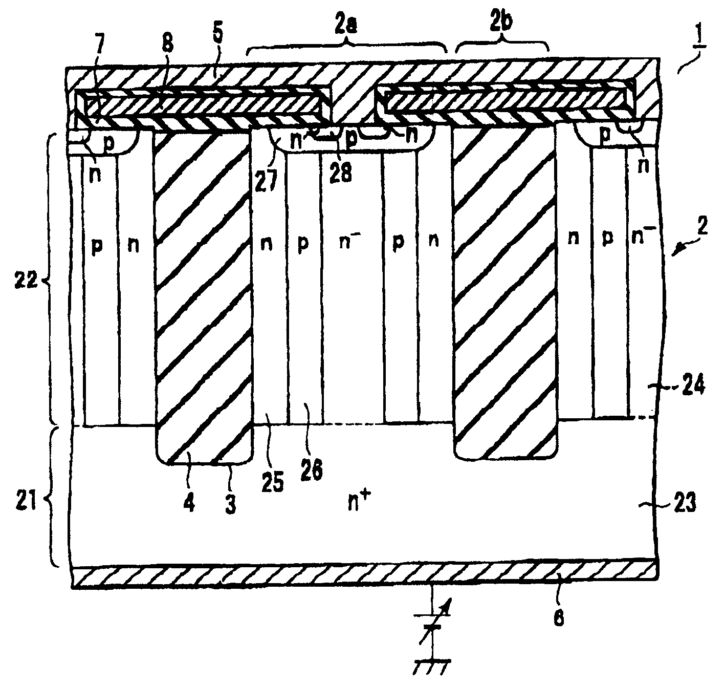
图1是示意性地表示本发明第1实施方案的半导体器件的剖面图;1 is a cross-sectional view schematically showing a semiconductor device according to a first embodiment of the present invention;
图2是示意性地表示图1的半导体器件的半导体衬底的平面图;2 is a plan view schematically showing a semiconductor substrate of the semiconductor device of FIG. 1;
图3是示意性地表示本发明第1实施方案的半导体器件中可能采用的一例结构的剖面图;3 is a cross-sectional view schematically showing an example of a structure that may be employed in the semiconductor device according to the first embodiment of the present invention;
图4是示意性地表示本发明第2实施方案的半导体器件中可能采用的一例结构的剖面图;4 is a cross-sectional view schematically showing an example of a structure that may be employed in a semiconductor device according to a second embodiment of the present invention;
图5是示意性地表示本发明第3实施方案的半导体器件中可能采用的一例结构的剖面图;5 is a cross-sectional view schematically showing an example of a structure that may be employed in a semiconductor device according to a third embodiment of the present invention;
图6是示意性地表示本发明第4实施方案的半导体器件中可能采用的一例结构的剖面图;6 is a cross-sectional view schematically showing an example of a structure that may be employed in a semiconductor device according to a fourth embodiment of the present invention;
图7是放大表示图6的粒状绝缘层的图;Fig. 7 is an enlarged view showing the granular insulating layer of Fig. 6;
图8是示意性地表示本发明第5实施方案的半导体器件中可能采用的一例结构的剖面图;8 is a cross-sectional view schematically showing an example of a structure that may be employed in a semiconductor device according to a fifth embodiment of the present invention;
图9是示意性地表示本发明第6实施方案的半导体器件中可能采用的一例结构的剖面图;9 is a cross-sectional view schematically showing an example of a structure that may be employed in a semiconductor device according to a sixth embodiment of the present invention;
图10是示意性地表示本发明第7实施方案的半导体器件中可能采用的一例结构的剖面图;10 is a cross-sectional view schematically showing an example of a structure that may be employed in a semiconductor device according to a seventh embodiment of the present invention;
图11是示意性地表示本发明第8实施方案的半导体器件中可能采用的一例结构的剖面图;11 is a cross-sectional view schematically showing an example of a structure that may be employed in a semiconductor device according to an eighth embodiment of the present invention;
图12是示意性地表示本发明第9实施方案的半导体器件中可能采用的一例结构的剖面图。Fig. 12 is a cross-sectional view schematically showing an example of a structure that may be employed in a semiconductor device according to a ninth embodiment of the present invention.
具体实施方式Detailed ways
以下,边参照附图边说明本发明的方案。另外,各图中,对于具有同样或类似功能的构成要素,给予同一参照标号,并省略重复说明。Hereinafter, aspects of the present invention will be described with reference to the drawings. In addition, in each figure, the same reference numerals are assigned to components having the same or similar functions, and repeated explanations are omitted.
图1是示意性地表示本发明第1实施方案的半导体器件的剖面图。图2是示意性地表示图1的半导体器件的半导体衬底的平面图。FIG. 1 is a cross-sectional view schematically showing a semiconductor device according to a first embodiment of the present invention. FIG. 2 is a plan view schematically showing a semiconductor substrate of the semiconductor device of FIG. 1 .
图1中所示的半导体器件1包括纵向型功率MOSFET。该半导体器件1具备半导体衬底2。如图2所示,该半导体衬底2的一个主面上,形成有元件区2a和元件隔离区2b。这些元件隔离区2b相当于图1中所示半导体衬底的槽3或埋入其中的绝缘层4。并且,各槽3的宽度例如在3μm~15μm范围内,深度例如在20μm~70μm范围内。A semiconductor device 1 shown in FIG. 1 includes a vertical type power MOSFET. This semiconductor device 1 includes a
半导体衬底2的上面,设置有源极电极5作为共同电极。另一方面,半导体衬底2的下面,设置有漏极电极6作为共同电极。即,图1的半导体器件1,在半导体衬底2的厚度方向,这里为纵向方向流动漏电流。On the upper surface of the
半导体衬底2具备用作高浓度漏极区23的第1导电型,这里为n+型的第1半导体层21,和低于第1半导体层21杂质浓度的第1导电型,这里为n-型的第2半导体层22。第1半导体层21例如是硅衬底,第2半导体层22例如是用外延生长法等形成于第1半导体层21上的硅层。The
该半导体衬底2上设置有槽3,并以绝缘层4埋入这些槽3内。在与绝缘层4侧面邻接的半导体衬底2表面区,形成有第1导电型,这里是n型的杂质扩散区25。并且,在与半导体衬底2的杂质扩散区25邻接的区域,形成有第2导电型,这里是p型的杂质扩散区26。这些杂质扩散区25、26,例如,在用绝缘层4埋入槽3之前从槽3的侧壁向半导体衬底2注入杂质,而后,通过在半导体衬底2中扩散杂质,并使之激活来得到。
在半导体衬底2的源极电极5一侧表面区,形成有第2导电型,这里是p型的基区27。在这些基区27内,例如用杂质扩散法等,形成有第1导电型,这里是n型的源极区28。In the surface region of the
在形成了半导体衬底2的源极区28的表面上,介以栅绝缘膜7形成有栅极8。各栅极8与夹着衬底2表面之中的至少绝缘层4的一对源极区28间的部分对置。并且,各元件区2a中,源极电极5连接到被绝缘层4夹着的一对源极区28和基区27。On the surface of the
在本实施方案中,图1中所示半导体器件1的绝缘层4采用以下的结构。In this embodiment, the insulating
图3是示意性地表示本发明第1实施方案的半导体器件中可能采用的一例结构的剖面图。图3所示结构中,绝缘层4含有绝缘粒子41,多数绝缘粒子41没有互相粘合起来,典型地说,槽3的侧壁和底面也没有粘合。并且,绝缘粒子41在槽3内形成有粒状绝缘层42。Fig. 3 is a cross-sectional view schematically showing an example of a structure that may be employed in the semiconductor device according to the first embodiment of the present invention. In the structure shown in FIG. 3, the insulating
如果采用这种结构,绝缘粒子41随半导体衬底2和/或绝缘粒子41的膨胀或收缩可在槽3内移动。因此,对半导体衬底2提供激活退火等热处理的场合,即使发生半导体衬底2和/或绝缘粒子41的膨胀或收缩,也能防止给半导体衬底2施加很强的应力。因此,变成能够抑制因热处理而在半导体衬底2上发生裂纹等缺陷。If this structure is employed, the insulating
另外,即使对很大的槽3而言,也很容易形成粒状绝缘层42。例如,首先,准备将绝缘粒子41分散在有机溶剂等的分散溶媒中的悬浮液。其次,在半导体衬底2形成有槽3的表面上涂布该悬浮液。然后,从该涂膜中除去分散溶媒。这样以来,以绝缘粒子41埋入槽3。即,获得粒状绝缘层42。In addition, the granular insulating
在该方法中,例如,可用旋涂法等形成涂膜。另外,在该方法中,通过涂布悬浮液而得到涂膜的厚度和粒状绝缘层42的厚度没有很大差别。进而,若使用粒径较大的绝缘粒子41,由于绝缘粒子41变得容易发生沉降,因而旋涂时,位于槽3内涂膜里的绝缘粒子41难以排出槽到3外侧。因此,即使槽3巨大,也很容易例如用一次涂布形成足够厚度的粒状绝缘层42。In this method, for example, a coating film can be formed by a spin coating method or the like. In addition, in this method, the thickness of the coating film obtained by coating the suspension and the thickness of the granular insulating
另外,图3所示的结构中,绝缘层4还包括软溶性电介质层44。该软溶性电介质层44埋入槽3的上部。另外,软溶性电介质层44的熔点或软化点在绝缘粒子41能够稳定存在的温度范围内,即在不发生绝缘粒子41的熔融或绝缘粒子41之间互相粘合的温度范围内。In addition, in the structure shown in FIG. 3 , the insulating
如上述一样,绝缘粒子41不会互相粘合。槽3的侧壁和底面也没有粘合。因此,不堵塞槽3的开口的话,有时会在制造工艺的任何阶段,从槽3放出绝缘粒子41。从槽3放出的绝缘粒子41与灰尘等同,所以,有降低成品率的可能性。As mentioned above, the insulating
为此,要是在粒状绝缘层42上设置软溶性电介质层44的话,就能够防止从槽3放出绝缘粒子41。另外,软溶性电介质层44,例如,在激活退火等热处理时能够软化或熔融。因此,便没有起因于软溶性电介质层44的给半导体衬底2施加的很强的应力。因此,如果按照图3的结构,就能够防止从槽3放出绝缘粒子41,以及能够抑制因热处理而在半导体衬底2上发生裂纹等缺陷。Therefore, if the refractory dielectric layer 44 is provided on the granular insulating
另外,通过热处理熔融或软化的软溶性电介质层44能够浸透到粒状绝缘层42中。因此,有时粒状绝缘层42与软溶性电介质层44部分地重叠起来。In addition, the resolvable dielectric layer 44 melted or softened by heat treatment can penetrate into the granular insulating
在图3所示的结构中,进一步,在槽3的侧壁和底面上设置有阻挡绝缘层43。一般地说,硅衬底对有机溶剂的濡湿性不高。如果设置阻挡绝缘层43,就能够控制槽3的侧壁和底面与有机溶剂有关的濡湿性。因此,能够更容易形成粒状绝缘层42。另外,如果设置阻挡绝缘层43的话,就能够抑制从软溶性电介质层44向半导体衬底2扩散杂质。In the structure shown in FIG. 3 , further, a blocking insulating
作为本实施方案的例子,进行了以下的试验。首先,在硅衬底2上,用旋涂法涂布胶体二氧化硅,采用加热由此得到涂膜的办法除去涂膜中的分散溶媒。这样以来,形成由平均直径为0.3μm二氧化硅粒子41构成的粒状绝缘层42。另外,硅的热膨胀系数为4.1×10⁻⁶/℃,硅氧化物的热膨胀系数约为23×10-6/℃。然后,用CMP法除去附着于槽3外侧的二氧化硅粒子41。用该CMP法,削减槽3内的粒状绝缘层42的上部,减少厚度2μm~5μm左右。槽3的上部埋入BPSG(Boron-Phospho SilicateGlass:硼磷硅酸盐玻璃)膜作为软溶性电介质层44。另外,BPSG是在SiO2中添加B2O3和P2O5和/或P2O3组成的材料。对该结构,在氮气气氛中,1100℃下施加8小时热处理。其结果,粒状绝缘层42上发生裂纹,但是硅衬底2的槽3近旁没有发生缺陷。另外,形成软溶性电介质层44以后,没有二氧化硅粒子41向槽3外部扩散。As an example of this embodiment, the following tests were conducted. First, colloidal silica is coated on the
为了比较,进行了以下的试验。首先,在硅衬底2上用CVD法形成硅氧化膜。该硅氧化膜,在元件区2a上要形成为5μm或以上的厚度。其次,用CMP法除去硅氧化膜的位于槽3外侧的部分。对该结构,在氮气气氛中,1100℃下施加8小时热处理。其结果,硅衬底2的槽3近旁发生了缺陷。For comparison, the following tests were carried out. First, a silicon oxide film is formed on a
本实施方案中,作为绝缘粒子41的材料,可以使用例如,二氧化硅、二氧化钛、氧化锆、硅碳化物之类的碳化物及其混合物等。这些材料大多绝缘性高,耐热性优良,热膨胀系数大或与半导体衬底2大体相等。In this embodiment, as the material of the insulating
绝缘粒子41的平均直径,例如可以是100nm或以上。另外,绝缘粒子41的平均直径,可以是500nm或以下或槽3开口宽度一半或以下。The average diameter of the insulating
作为绝缘粒子41的材料,例如,使用胶体二氧化硅的场合,如果进行高温热处理,二氧化硅粒子发生约5%~15%左右的收缩。其收缩率随二氧化硅粒径而异。具体地说,粒径大的二氧化硅收缩率小,粒径小的二氧化硅收缩率大。通常,平均粒径在100nm或以上的二氧化硅,收缩率充分地小。但是,多数场合,难以制造二氧化硅的平均粒径超过500nm的单分散(monodisperse)胶体二氧化硅。When colloidal silica is used as the material of the insulating
实际上,使用胶体二氧化硅,对宽度为5μm而且深度为50μm或以上的槽3进行埋入。在使用二氧化硅的平均粒径为50nm的胶体二氧化硅的场合,埋入工艺的成品率为10%或以下。相对于此,对使用二氧化硅的平均粒径为150nm和300nm胶体二氧化硅的场合,埋入工艺的成品率全都是90%或以上。Actually, using colloidal silica, the
作为绝缘粒子41,可以使用熔点或软化点比形成粒状绝缘层42以后进行的热处理的最高温度还要高的粒子。例如,作为绝缘粒子41,可以使用熔点或软化点高于1100℃的材料。典型地说,作为绝缘粒子41,使用在形成粒状绝缘层42以后进行的热处理的最高温度下是稳定的,即不发生熔融或粘合的绝缘粒子。As the insulating
作为软溶性电电介质层44的材料,使用其熔点或软化点在绝缘粒子41能稳定存在的温度范围内,即不发生绝缘粒子41的熔融或绝缘粒子41之间互相粘合的温度范围内的材料。典型地说,作为软溶性电介质层44的材料,使用其熔点或软化点比在形成粒状绝缘层42以后进行的热处理的最高温度还低的材料。作为此种材料,例如,可以举出硅酸盐玻璃之类的玻璃。作为这种玻璃,例如,可以举出BPSG、BSG(Boron Silicate Glass:硼硅酸盐玻璃)、PSG(Phospho Silicate Glass:磷硅酸盐玻璃)等之类添加了杂质的硅酸盐玻璃等。As the material of the soft-melting dielectric layer 44, one whose melting point or softening point is within the temperature range in which the insulating
对软溶性电介质层44的厚度没有特别限制,但是一般,软溶性电介质层44要以构成其下层粒状绝缘层42的绝缘粒子41的粒径的3倍或以上的厚度来形成。例如,软溶性电介质层44的厚度,可设为约1μm~4μm的范围内。The thickness of the soft-melting dielectric layer 44 is not particularly limited, but generally, the soft-melting dielectric layer 44 is formed to be three times or more thick than the particle diameter of the insulating
作为阻挡绝缘层43的材料,例如,可以举出硅氧化物、硅氮化物、它们的混合物等。阻挡绝缘层43,例如,可用LP(Low Pressure:低压)CVD法之类的CVD法或热氧化法来形成。Examples of the material of the
作为形成粒状绝缘层42用悬浮液的分散溶媒,例如,可以使用醇类、多元醇类、醚类、酯类、酮类、其混合物等有机溶剂。作为醇类言,例如,可举出乙醇、异丙醇、环己醇等。作为多元醇类,例如,可举出乙二醇、二甘醇、聚丙二醇等。作为醚类,例如,可举出丙二醇醚这样的乙二醇醚等。作为酯类,例如,可举出乙酸乙酯等。作为酮类,例如,可举出环己酮或丁内酯等。As the dispersion medium for the suspension for forming the granular insulating
接着,说明本发明第2实施方案。第2实施方案,除绝缘层4采用以下的结构外,都与第1实施方案同样。Next, a second embodiment of the present invention will be described. The second embodiment is the same as the first embodiment except that the insulating
图4是示意性地表示本发明第2实施方案的半导体器件中可能采用一例结构的剖面图。图4所示的结构中,绝缘层4由粒状绝缘层42构成。该粒状绝缘层42包括平均粒径较大的第1绝缘粒子41a和平均粒径较小的第2绝缘粒子41b,将这些第1和第2绝缘粒子41a、41b大致均匀地混合起来。Fig. 4 is a cross-sectional view schematically showing an example of a structure that may be employed in a semiconductor device according to a second embodiment of the present invention. In the structure shown in FIG. 4 , the insulating
本实施方案也与第1实施方案同样,通过热处理成为能够抑制半导体衬底2上发生裂纹等缺陷。另外,本实施方案也与第1实施方案同样,即使是槽3巨大,粒状绝缘层42也很容易地形成。进一步,本实施方案中,由于使用平均粒径不同的第1和第2绝缘粒子41a、41b,有以下特征。In this embodiment, as in the first embodiment, it is possible to suppress defects such as cracks on the
平均粒径较大的第1绝缘粒子41a,可以容易而且较厚地形成粒状绝缘层42。但是,如果仅以平均粒径大的第1绝缘粒子41a形成粒状绝缘层42的话,很多情况下,就难以获得平坦性优异的粒状绝缘层42。The first
在本实施方案中,如上所述,除平均粒径较大的第1绝缘粒子41a外,还使用平均粒径较小的第2绝缘粒子41b。平均粒径较小的第2绝缘粒子41b起提高粒状绝缘层42平坦性的作用。因此,按照本实施方案,就很容易形成足够厚而且平坦性优异的粒状绝缘层42。In the present embodiment, as described above, in addition to the first insulating
在本实施方案中,作为第1和第2绝缘粒子41a、41b的材料,例如,可以使用第1实施方案中关于绝缘粒子41示出的材料。第1绝缘粒子41a的材料和第2绝缘粒子41b的材料也可以是同样的,或者也可以是不同的。In this embodiment, as the materials of the first and second
第1绝缘粒子41a的平均直径,例如,可以是100nm或以上。另外,第1绝缘粒子41a的平均直径,也可以是500nm或以下或槽3开口宽度一半或以下。第2绝缘粒子41b的平均直径,只要比第1绝缘粒子41a的平均直径小就行,也可以是不足100nm。例如,可以把平均直径400nm的第1绝缘粒子41a和平均直径70nm的第2绝缘粒子41b组合起来使用。但是,典型地是将平均直径在250nm~350nm范围内的第1绝缘粒子41a和平均直径在125nm~175nm范围内的第2绝缘粒子41b组合起来使用。The average diameter of the first insulating
粒状绝缘层42可以进一步含有与第1和第2绝缘粒子41a、41b平均直径不同的一种或以上绝缘粒子。另外,粒状绝缘层42含有平均直径不同的多种绝缘粒子,例如,在粒度分布具有二个或以上峰值的场合就可以确定。另外,即使粒度分布只有一个峰值的场合,如果使用材料互相不同的多种绝缘粒子,采用求出每种材料绝缘粒子平均直径的办法,往往也能确定粒状绝缘层42含有平均直径不同的多种绝缘粒子。The granular insulating
作为本方案的例子,进行了以下的试验。首先,在硅衬底2上,用旋涂法涂布胶体二氧化硅,采用加热由此得到的涂膜的办法除去涂膜中的分散溶媒。这里,混合使用二氧化硅的平均直径互相不同的二种胶体二氧化硅。这样以来,形成由平均直径为0.3μm的二氧化硅粒子41a和由平均直径为0.15μm的二氧化硅粒子41b构成的粒状绝缘层42。然后,用CMP法,除去附着于槽3外侧的二氧化硅粒子41。对该结构,在氮气气氛中,1100℃下施加8小时热处理。其结果,粒状绝缘层42上发生了裂纹,但硅衬底2的槽3近旁没有发生缺陷。另外,在本例中所得的粒状绝缘层42的表面比第1实施方案所得粒状绝缘层42的表面在平坦性方面优异。As an example of this aspect, the following tests were conducted. First, colloidal silica is coated on a
其次,说明本发明第3实施方案。第3实施方案,除不混合第1绝缘粒子41a和第2绝缘粒子41b,层叠第1绝缘粒子41a的粒状绝缘层和第2绝缘粒子41b的粒状绝缘层外,都与第2实施方案相同。Next, a third embodiment of the present invention will be described. The third embodiment is the same as the second embodiment except that the first insulating
图5是示意性地表示本发明第3实施方案的半导体器件中可能采用的一例结构的剖面图。图5所示的结构中,绝缘层4由粒状绝缘层42构成。该粒状绝缘层42包括由第1绝缘粒子41a构成的第1粒状绝缘层42a和由第2绝缘粒子41b构成的第2粒状绝缘层42b。Fig. 5 is a cross-sectional view schematically showing an example of a structure that may be employed in a semiconductor device according to a third embodiment of the present invention. In the structure shown in FIG. 5 , the insulating
在本实施方案中,如图5所示,由平均粒径较大的第1绝缘粒子41a构成第1粒状绝缘层42a,在其上,设置由平均直径较小的第2绝缘粒子41b构成的第2粒状绝缘层42b。若采用这样的结构,就能够形成平坦性更加优异的粒状绝缘层42。In this embodiment, as shown in FIG. 5 , the first granular insulating
另外,也可以由平均粒径较小的第2绝缘粒子41b构成第2粒状绝缘层42b,在其上,设置由平均直径较大的第1绝缘粒子41a构成的第1粒状绝缘层42a。即,也可以把第1粒状绝缘层42a与第2粒状绝缘层42b的层叠次序倒过来。但是,这时,不能实现按图5所示顺序层叠第1粒状绝缘层42a和第2粒状绝缘层42b的场合那样的高平坦性。Alternatively, the second granular insulating
粒状绝缘层42可以进一步含有与第1和第2粒状绝缘层42a、42b绝缘粒子的平均直径不同的一层或以上的粒状绝缘层。这时,典型地,把绝缘粒子平均直径最小的粒状绝缘层作为最上层。例如,确定粒状绝缘层的排列顺序,以使越朝向深部绝缘粒子的平均直径变得越大。The granular insulating
作为本方案的例子,进行了以下的试验。首先,在硅衬底2上,用旋涂法涂布含有平均直径较大的胶体二氧化硅,采用加热由此得到涂膜的办法除去涂膜中的分散溶媒。这样以来,形成由平均直径为0.3μm的二氧化硅粒子41a构成的第1绝缘层42a。然后,用CMP法,除去附着于槽3外侧的二氧化硅粒子41a。接着,在硅衬底2上,用旋涂法涂布含有平均直径较小的胶体二氧化硅,采用加热由此得到涂膜的办法除去涂膜中的分散溶媒。这样以来,形成由平均直径为0.15μm的二氧化硅粒子41b构成的第2绝缘层42b。然后,用CMP法,除去附着于槽3外侧的二氧化硅粒子41b。对该结构,在氮气气氛中,1100℃下施加8小时热处理。其结果,粒状绝缘层42上发生裂纹,但硅衬底2的槽3近旁没有发生缺陷。另外,本例中所得粒状绝缘层42的表面比第2实施方案所得粒状绝缘层42的表面在平坦性方面还要优良。As an example of this aspect, the following tests were conducted. First, colloidal silica containing a large average diameter is coated on the
接着,说明本发明第4实施方案。第4实施方案,除对绝缘层4采用以下的结构外,都与第1实施方案同样。Next, a fourth embodiment of the present invention will be described. The fourth embodiment is the same as the first embodiment except that the insulating
图6是示意性地表示本发明第4实施方案的半导体器件中可能采用的一例结构的剖面图。图7是放大表示图6的粒状绝缘层42的图。图6所示的结构中,绝缘层4由粒状绝缘层42构成。该粒状绝缘层42包括由绝缘粒子41和交联绝缘粒子的绝缘粘合剂45。即,如图7所示,绝缘粒子41与绝缘粘合剂45形成网状结构。Fig. 6 is a cross-sectional view schematically showing an example of a structure that may be employed in a semiconductor device according to a fourth embodiment of the present invention. FIG. 7 is an enlarged view showing the granular insulating
如第1实施方案中说明的那样,在绝缘粒子41不互相粘合而且槽3的侧壁和底面也没有粘合的场合,不堵塞槽3的开口的话,有在制造工艺的任何阶段,绝缘粒子41从槽3向其外部扩散。本实施方案中,如上所述,通过绝缘粘合剂45使绝缘粒子41之间互相粘合。因此,即使不会堵塞槽3的开口,也能相当程度抑制绝缘粒子41从槽3向外部扩散。As explained in the first embodiment, in the case where the insulating
进而在本实施方案中,绝缘粒子41与绝缘粘合剂45形成网状结构。这样,粒状绝缘层42的变形变得容易发生,因而缓和因温度变化而发生的应力。另外,加上过剩应力的情况下,绝缘粒子41或从绝缘粘合剂45剥离,或者绝缘粘合剂45被切断,所以应力被缓和。可是,通常如此的剥离或切断,因为仅发生于粒状绝缘层42的局部,所以几乎不发生起源于此的灰尘。因此,与第1实施方案同样,本实施方案也能够防止绝缘粒子41从槽3放出,以及能够抑制因热处理而在半导体衬底2上发生裂纹等的缺陷。Furthermore, in the present embodiment, the insulating
另外,在本实施方案中,也与第1实施方案同样,粒状绝缘层42即使对槽3是巨大的,也很容易形成。例如,首先,准备含有绝缘粒子41和绝缘粘合剂45的材料及有机溶剂等的分散溶媒的悬浮液。作为绝缘粘合剂45的材料,例如,可使用SOG等。其次,在半导体衬底2形成了槽3的表面上涂布该悬浮液。然后,对该涂膜提供例如约400℃的热处理。由此,从涂膜除去分散溶媒的同时,使硅烷醇聚合。这样以来,用绝缘粒子41和绝缘粘合剂45埋入槽3。即,得到粒状绝缘层42。Also in this embodiment, as in the first embodiment, even if the granular insulating
在该方法中,例如,可以用旋涂法等形成涂膜。另外,在该方法中,通过涂布悬浮液而得到的涂膜厚度和粒状绝缘层42的厚度之间没有很大差别。进而,若使用粒径比较大的绝缘粒子41,由于绝缘粒子41变得容易发生沉降,因而旋涂时,位于槽3内涂膜里的绝缘粒子41难以排出槽3外侧。因此,即使是槽3巨大,也很容易,例如用一次涂布形成足够厚度的粒状绝缘层42。In this method, for example, a coating film can be formed by a spin coating method or the like. In addition, in this method, there is no great difference between the thickness of the coating film obtained by coating the suspension and the thickness of the granular insulating
另外,绝缘粒子41和绝缘粘合剂45形成网状结构的粒状绝缘层42,例如,可通过在悬浮液中的相对于绝缘粒子41将绝缘粘合剂45的材料的比率设定为较低的办法,很容易形成。In addition, the insulating
作为绝缘粘合剂45的材料,例如,可使用将如以下化学式表示的这种硅烷醇溶解于有机溶剂形成的无机SOG和有机SOG等SOG。另外,使用于无机SOG和有机SOG中的硅烷醇不仅限于下面化学式表示的物质。例如,在无机SOG和有机SOG中所用的硅烷醇中,也可以将与Si原子键合的-OH基和-O-的一部分置换成-H基。另外,对于有机SOG中所用的硅烷醇,也可以将-CH3基置换成-C2H5基等其它烷基。另外,在有机SOG中所用的硅烷醇中,也可以将与Si原子键合的-OH基和-O-的一部分置换成-CH3基、或-C2H5基等的烷基。As a material of the insulating
无机SOG和有机SOG,如以下反应式所示,通过不管什么烧成法形成硅氧化物。但是,在使用有机SOG得到的硅氧化物中会残留碳化氢基。因此,一般地说,无机SOG与有机SOG相比,热稳定性方面较为优良。Inorganic SOG and organic SOG form silicon oxide by any firing method as shown in the following reaction formula. However, hydrocarbon groups remain in silicon oxide obtained using organic SOG. Therefore, in general, inorganic SOG is better in thermal stability than organic SOG.
在本实施方案中,用于形成粒状绝缘层42的悬浮液中的绝缘粘合剂45的浓度,例如,可以规定为20体积%~45体积%的范围内。如果绝缘粘合剂45的浓度过低,就难以覆盖全体粒状绝缘层42通过绝缘粘合剂45使绝缘粒子41之间互相粘合。另外,如果绝缘粘合剂45的浓度过高,除绝缘粒子41和绝缘粘合剂45难以形成网状结构外,粒状绝缘层42本身也变得容易发生裂纹。进而,作为绝缘粘合剂45的材料使用例如SOG的情况下,绝缘粘合剂45如果进行高温热处理,就发生约5%~约20%的收缩。由于绝缘粘合剂45的一部分与槽3的侧壁和底面粘合,因此如果粒状绝缘层42中绝缘粘合剂45的浓度过高,高度热处理时,粒状绝缘层42往往给半导体衬底2造成过度应力。而且,粒状绝缘层42中绝缘粘合剂45的浓度高的情况下,有时用CMP法,不能完全除去位于槽3外部的绝缘粒子41和绝缘粘合剂45。In the present embodiment, the concentration of the insulating
作为本实施方案,进行了以下的试验。首先,在硅衬底2上用旋涂法涂布胶体二氧化硅和无机SOG的混合液,对由此得到的涂膜提供约120℃的热处理。这里,使用以20体积%、50体积%、80体积%的浓度含有无机SOG的溶液作为前面的混合液。这样以来,形成由平均直径为0.3μm的二氧化硅粒子41和绝缘粘合剂45构成的粒状绝缘层42。然后,用CMP法,除去附着于槽3外侧的二氧化硅粒子41和绝缘粘合剂45。对此结构,在氮气气氛中,1100℃下施加8小时热处理。As this embodiment, the following tests were conducted. First, a mixed solution of colloidal silica and inorganic SOG was coated on a
其结果,以50体积%、80体积%的浓度中含有无机SOG的溶液作为前面的混合液的场合,硅衬底2的槽3近旁发生缺陷。相对于此,以20体积%的浓度中含有无机SOG的溶液作为前面的混合液的场合,虽然粒状绝缘层42中发生裂纹,但硅衬底2的槽3近旁不发生缺陷。As a result, when a solution containing inorganic SOG at a concentration of 50% by volume or 80% by volume was used as the previous mixed solution, defects occurred near the
接着,说明本发明第5实施方案。第5实施方案,除绝缘层4采用以下的结构外,与第1实施方案相同。Next, a fifth embodiment of the present invention will be described. The fifth embodiment is the same as the first embodiment except that the insulating
图8是示意性地表示本发明第5实施方案的半导体器件中可能采用的一例结构的剖面图。图8所示的结构中,绝缘层4由粒状绝缘层42构成。该粒状绝缘层42包括第1粒状绝缘层42a和第2粒状绝缘层42b。Fig. 8 is a cross-sectional view schematically showing an example of a structure that may be employed in a semiconductor device according to a fifth embodiment of the present invention. In the structure shown in FIG. 8 , the insulating
第1粒状绝缘层42a由第1绝缘粒子41a构成,并且不含有粘合剂。另一方面,第2粒状绝缘层42b含有第2绝缘粒子41b和绝缘粘合剂45。The first granular insulating
在本结构中,如上述一样,绝缘层4具有不含有粘合剂的第1粒状绝缘层42a。因此,与参照图6说过的结构相比,能够更有效地抑制通过热处理导致的半导体衬底2上发生裂纹等的缺陷。In this structure, as mentioned above, the insulating
另外,在该结构中,在不含有粘合剂的第1粒状绝缘层42a上面被覆盖有含有绝缘粘合剂45的第2粒状绝缘层42b。因此,除难于从第2粒状绝缘层42b向槽3外部扩散第2绝缘粒子41b外,也难以发生从第1粒状绝缘层42a向槽3外部扩散第1绝缘粒子41a。Moreover, in this structure, the 2nd granular insulating
在本实施方案中,通常,第2粒状绝缘层42b相对于粒状绝缘层42的厚度比很小,例如,第2粒状绝缘层42b的厚度可以为约1μm~约5μm范围内。因此,在第2粒状绝缘层42b中,第2绝缘粒子41b和绝缘粘合剂45可以形成网状结构,或者,也可以不形成网状结构。In this embodiment, generally, the thickness ratio of the second granular insulating
本实施方案中,第1绝缘粒子41a和第2绝缘粒子41b,材料可以相同,或者,也可以是不同的。In this embodiment, the materials of the first insulating
另外,本实施方案中,第1绝缘粒子41a和第2绝缘粒子41b,平均直径可以相同,或者,也可以是不同的。例如,第2绝缘粒子41b的平均直径可以比第1绝缘粒子41a的平均直径小。即,在本实施方案中说,也可以进一步组合第3实施方案的技术。In addition, in the present embodiment, the average diameters of the first insulating
另外,在本实施方案中,第2粒状绝缘层42b,可以含有平均直径较大的绝缘粒子和较小的绝缘粒子作为绝缘粒子41b。同样,第1粒状绝缘层42a,也可以含有平均直径较大的绝缘粒子和较小的绝缘粒子作为绝缘粒子41a。即,在本实施方案中,也可以进一步组合第2实施方案的技术。In addition, in this embodiment, the second granular insulating
作为本实施方案,进行了以下的试验。首先,在硅衬底2上用旋涂法涂布胶体二氧化硅,通过加热由此得到的涂膜,从涂膜除去分散溶媒。然后,用CMP法,除去附着于槽3外侧的二氧化硅粒子41a。这样以来,形成由平均直径为0.3μm的二氧化硅粒子41a构成的第1粒状绝缘层42a。接着,在硅衬底2上用旋涂法涂布胶体二氧化硅和无机SOG的混合液,对由此得到的涂膜提供一度约120℃的热处理。然后,用CMP法,除去附着于槽3外侧的二氧化硅粒子41b和绝缘粘合剂45。这里,作为第2粒状绝缘层42b的混合液,使用以20体积%、30体积%、35体积%、45体积%、50体积%的浓度含有无机SOG的溶液。对此结构,在氮气气氛中,1100℃下施加8小时热处理。As this embodiment, the following tests were conducted. First, colloidal silica is coated on a
其结果,使用以45体积%、50体积%的浓度含有无机SOG的溶液作为前面的混合液的场合,用CMP法,难以完全除去附着于槽3外侧的二氧化硅粒子41b和绝缘粘合剂45。相对于此,使用以20体积%、30体积%、35体积%的浓度含有无机SOG的溶液作为前面的混合液的场合,虽然粒状绝缘层42上发生裂纹,但是硅衬底2的槽3近旁不发生缺陷。另外,在槽3的外侧也没有残留二氧化硅粒子41b和绝缘粘合剂45。另外,使用以20体积%、30体积%、35体积%、45体积%的浓度含有无机SOG的溶液作为前面的混合液的场合,通过粒状绝缘层42埋入槽3的成品率分别是45%、90%、90%、65%。As a result, when a solution containing inorganic SOG at a concentration of 45% by volume or 50% by volume is used as the previous mixed solution, it is difficult to completely remove the
接着,用电子显微镜观察热处理后的粒状绝缘层42。其结果,在使用以20体积%、30体积%、35体积%的浓度含有无机SOG的溶液作为前面的混合液的粒状绝缘层42中,可以确认,二氧化硅粒子41和绝缘粘合剂45形成了网状结构。另外,在使用以45体积%、50体积%的浓度含有无机SOG的溶液作为前面的混合液的粒状绝缘层42中,可以确认,二氧化硅粒子41b和绝缘粘合剂45大体上是连续相,二氧化硅粒子41b和绝缘粘合剂45没有形成网状结构。Next, the heat-treated granular insulating
可以互相组合以上说明的第1到第5实施方案的技术,在以下的实施方案中说明这种组合的例子。The techniques of the first to fifth embodiments described above can be combined with each other, and examples of such combinations will be described in the following embodiments.
首先,说明本发明的第6实施方案。第6实施方案相当于第1和第4First, a sixth embodiment of the present invention will be described. The sixth embodiment corresponds to the first and fourth
实施方案的技术组合。Implementation technology combination.
图9是示意性地表示本发明的第6实施方案中可能采用的一例结构的剖面图。图9所示的结构中,绝缘层4包括粒状绝缘层42和软溶性电介质层44。粒状绝缘层42包括绝缘粒子41和将其交联的绝缘粘合剂45。Fig. 9 is a cross-sectional view schematically showing an example of a structure that may be employed in the sixth embodiment of the present invention. In the structure shown in FIG. 9 , the insulating
倘若采用这样的结构,就能够达到第1和第4实施方案说明的效果。此外,倘若采用该结构,形成软溶性电介质层44以后,就可以进一步确实防止绝缘粒子41扩散到槽3的外部。With such a structure, the effects described in the first and fourth embodiments can be achieved. In addition, according to this structure, after the soft-soluble dielectric layer 44 is formed, the diffusion of the insulating
接着,说明本发明的第7实施方案。第7实施方案相当于第2和第4Next, a seventh embodiment of the present invention will be described. The seventh embodiment corresponds to the second and fourth
实施方案的技术组合。Implementation technology combination.
图10是示意性地表示本发明的第7实施方案中可能采用的一例结构的剖面图。图10所示的结构中,绝缘层4由粒状绝缘层42构成。粒状绝缘层42包括大体均匀混合的第1绝缘粒子41a和第2绝缘粒子41b,以及将其交联的绝缘粘合剂45。倘若采用这样的结构,就能够达到第2和第4实施方案说明的效果。Fig. 10 is a cross-sectional view schematically showing an example of a structure that may be employed in the seventh embodiment of the present invention. In the structure shown in FIG. 10 , the insulating
接着,说明本发明的第8实施方案。第8实施方案相当于第3和第4Next, an eighth embodiment of the present invention will be described. The eighth embodiment corresponds to the third and fourth
实施方案的技术组合。Implementation technology combination.
图11是示意性地表示本发明的第8实施方案中可能采用的一例结构的剖面图。图11所示的结构中,绝缘层4包括第1粒状绝缘层42a和第2粒状绝缘层42b。第1粒状绝缘层42a含有平均直径较大的第1绝缘粒子41a和将其交联的绝缘粘合剂45。另一方面,第2粒状绝缘层42b含有平均直径较小的第2绝缘粒子41b和将其交联的绝缘粘合剂45。倘若采用这样的结构,就能够达到第3和第4实施方案中说明的效果。另外,在本实施方案中,第1粒状绝缘层42a的绝缘粘合剂45和第2粒状绝缘层42b的绝缘粘合剂45,材料可以相同,或者也可以是不同的。Fig. 11 is a cross-sectional view schematically showing an example of a structure that may be employed in an eighth embodiment of the present invention. In the structure shown in FIG. 11, the insulating
接着,说明本发明的第9实施方案。第9实施方案相当于第1和第5Next, a ninth embodiment of the present invention will be described. The ninth embodiment is equivalent to the first and fifth
实施方案的技术组合。Implementation technology combination.
图12是示意性地表示本发明的第9实施方案中可能采用的一例结构的剖面图。图12所示的结构中,绝缘层4包括第1粒状绝缘层42a、第2粒状绝缘层42b和软溶性电介质层44。第1粒状绝缘层42a由绝缘粒子41a构成。另一方面,第2粒状绝缘层42b含有绝缘粒子41b和绝缘粘合剂45。Fig. 12 is a cross-sectional view schematically showing an example of a structure that may be employed in a ninth embodiment of the present invention. In the structure shown in FIG. 12 , the insulating
倘若采用这样的结构,就能够达到第1和第5实施方案中说明的效果。另外,在本实施方案中,在软溶性电介质层44与第1粒状绝缘层42a之间,介在有包括绝缘粒子41b和绝缘粘合剂45的第2粒状绝缘层42b。在第2粒状绝缘层42b含有绝缘粒子41b和绝缘粘合剂45的场合,与第2粒状绝缘层42b不含有绝缘粘合剂45的场合相比,通过热处理熔融或软化的软溶性电介质层44难以浸透到第2粒状绝缘层42b中。因此,在该结构中,可抑制熔融或软化的软溶性电介质层44向第1粒状绝缘层42a中浸透。从缓和热应力的观点看,优选尽可能限度地减小软溶性电介质层44与绝缘粒子41a等的接触面积。因此,倘若采用本结构,例如,即使多次进行热处理,也没有明显丧失抑制半导体衬底2上发生裂纹等缺陷的效果。With such a structure, the effects described in the first and fifth embodiments can be achieved. In addition, in this embodiment, the second granular insulating
另外,图12所示结构,以覆盖绝缘层9被覆软溶性电介质层44。覆盖绝缘层9的熔点或软化点比软溶性电介质层44要高。典型地说,覆盖绝缘层9的熔点或软化点,比形成粒状绝缘层42以后进行的热处理的最高温度还要高。In addition, in the structure shown in FIG. 12 , the soft-soluble dielectric layer 44 is covered with the cover insulating layer 9 . The melting point or softening point of the covering insulating layer 9 is higher than that of the refractory dielectric layer 44 . Typically, the melting point or softening point of the covering insulating layer 9 is higher than the maximum temperature of the heat treatment performed after the granular insulating
在该结构中,软溶性电介质层44将阻挡绝缘层43和覆盖绝缘层9包围起来。因此,能够抑制软溶性电介质层44中的元素向半导体衬底2等中扩散。In this structure, the soft-soluble dielectric layer 44 surrounds the blocking insulating
覆盖绝缘层9的材料只要熔点或软化点满足前面的条件,就没有特别限制。作为覆盖绝缘层9的材料,可以举出例如,硅氧化物等氧化物、硅氮化物等氮化物、以及其混合物等。The material of the covering insulating layer 9 is not particularly limited as long as the melting point or softening point satisfies the foregoing conditions. Examples of the material for the insulating cover layer 9 include oxides such as silicon oxide, nitrides such as silicon nitride, and mixtures thereof.
另外,图12所示结构中,将阻挡绝缘层43制成与覆盖绝缘层9大体相同形状的图形。这种结构,例如,在用于覆盖绝缘层9形成图形的蚀刻时,阻挡绝缘层43也可以同时进行蚀刻,或者通过进行利用覆盖绝缘层9作为掩模的蚀刻而获得。In addition, in the structure shown in FIG. 12 , the blocking insulating
第6到第9实施方案相当于第1~第3实施方案的至少一种技术与第4或第5实施方案的技术的组合,然而对第1到第5实施方案的技术还有其它的组合。例如,也可以组合第1实施方案的技术和第2或第3方案的技术。另外,图12所示结构中,也可以省略覆盖绝缘层9和软溶性电介质层44的至少一方。进而,第9实施方案中说过的覆盖绝缘层9,也可以使用于其它实施方案的半导体器件中。The sixth to ninth embodiments correspond to combinations of at least one technique of the first to third embodiments and the techniques of the fourth or fifth embodiment, but there are other combinations of the techniques of the first to fifth embodiments . For example, the technology of the first embodiment and the technology of the second or third embodiment may be combined. In addition, in the structure shown in FIG. 12 , at least one of the cover insulating layer 9 and the refractory dielectric layer 44 may be omitted. Furthermore, the cover insulating layer 9 described in the ninth embodiment can also be used in semiconductor devices of other embodiments.
另外,在第1到第9实施方案中,应用于图1所示半导体器件的槽式隔离技术,也可以应用于其他结构的半导体器件中。上述模式隔离技术也适用于具备例如与图1所示结构不同的MOSFET的半导体器件。或者,前面的槽式隔离技术,也可以应用于具备例如,双极晶体管的半导体器件等。In addition, the trench isolation technology applied to the semiconductor device shown in FIG. 1 in the first to ninth embodiments can also be applied to semiconductor devices of other structures. The mode isolation technique described above is also applicable to a semiconductor device having, for example, a MOSFET having a structure different from that shown in FIG. 1 . Alternatively, the aforementioned trench isolation technology can also be applied to semiconductor devices equipped with, for example, bipolar transistors.
另外的优点和改进,对本领域普通技术人员将是显而易见。因此,本发明概括起来说并不限于这里表示和描述的具体细节和表现的各实施方案。因此,在不脱离由附属的权利要求书及其等同物所限定的本发明总构思的精神或范围内,应该能够进行各种各样的修改。Additional advantages and modifications will readily appear to those skilled in the art. Therefore, the invention in general is not limited to the specific details and embodied embodiments shown and described herein. Accordingly, various modifications should be possible without departing from the spirit or scope of the general inventive concept as defined by the appended claims and their equivalents.
Claims (29)
Applications Claiming Priority (2)
| Application Number | Priority Date | Filing Date | Title |
|---|---|---|---|
| JP127841/2002 | 2002-04-30 | ||
| JP2002127841 | 2002-04-30 |
Publications (2)
| Publication Number | Publication Date |
|---|---|
| CN1455446A CN1455446A (en) | 2003-11-12 |
| CN1237604C true CN1237604C (en) | 2006-01-18 |
Family
ID=29267665
Family Applications (1)
| Application Number | Title | Priority Date | Filing Date |
|---|---|---|---|
| CNB03122458XA Expired - Fee Related CN1237604C (en) | 2002-04-30 | 2003-04-28 | Semiconductor device |
Country Status (2)
| Country | Link |
|---|---|
| US (1) | US20040016962A1 (en) |
| CN (1) | CN1237604C (en) |
Families Citing this family (11)
| Publication number | Priority date | Publication date | Assignee | Title |
|---|---|---|---|---|
| US7253104B2 (en) * | 2003-12-01 | 2007-08-07 | Micron Technology, Inc. | Methods of forming particle-containing materials |
| JP4791723B2 (en) * | 2004-10-18 | 2011-10-12 | 株式会社東芝 | Semiconductor device and manufacturing method thereof |
| JP4116007B2 (en) * | 2005-03-04 | 2008-07-09 | 株式会社東芝 | Semiconductor device and manufacturing method thereof |
| JP2007012977A (en) * | 2005-07-01 | 2007-01-18 | Toshiba Corp | Semiconductor device |
| US9741309B2 (en) | 2009-01-22 | 2017-08-22 | Semiconductor Energy Laboratory Co., Ltd. | Method for driving display device including first to fourth switches |
| JP5225479B2 (en) | 2011-09-27 | 2013-07-03 | 有限会社 ナプラ | Semiconductor substrate, electronic device and manufacturing method thereof |
| JP5281188B1 (en) | 2012-11-26 | 2013-09-04 | 有限会社 ナプラ | Insulating paste, electronic device, and insulating part forming method |
| JP5575309B1 (en) * | 2013-08-05 | 2014-08-20 | 有限会社 ナプラ | Integrated circuit device |
| CN104765502B (en) * | 2015-04-27 | 2018-09-11 | 京东方科技集团股份有限公司 | A kind of touch-control display panel and preparation method thereof, control method |
| DE102016119031B4 (en) | 2016-10-07 | 2025-08-14 | Fraunhofer-Gesellschaft zur Förderung der angewandten Forschung e.V. | Thermally insulated microsystem |
| US20230067511A1 (en) * | 2021-08-26 | 2023-03-02 | IceMos Technology Limited | High-Breakdown Voltage, Low RDSON Electrical Component with Dissimilar Semiconductor Layers |
Family Cites Families (19)
| Publication number | Priority date | Publication date | Assignee | Title |
|---|---|---|---|---|
| US3634558A (en) * | 1968-10-29 | 1972-01-11 | Atomic Energy Commission | Method of producing monodisperse silica spheres having a dispersed radioactive tracer |
| US4544576A (en) * | 1981-07-27 | 1985-10-01 | International Business Machines Corporation | Deep dielectric isolation by fused glass |
| US4903107A (en) * | 1986-12-29 | 1990-02-20 | General Electric Company | Buried oxide field isolation structure with composite dielectric |
| US5719085A (en) * | 1995-09-29 | 1998-02-17 | Intel Corporation | Shallow trench isolation technique |
| KR0183886B1 (en) * | 1996-06-17 | 1999-04-15 | 김광호 | Trench device isolation method of semiconductor device |
| US6376893B1 (en) * | 1997-12-13 | 2002-04-23 | Hyundai Electronics Industries Co., Ltd. | Trench isolation structure and fabrication method thereof |
| US6444539B1 (en) * | 1998-05-20 | 2002-09-03 | Advanced Micro Devices, Inc. | Method for producing a shallow trench isolation filled with thermal oxide |
| US6017803A (en) * | 1998-06-24 | 2000-01-25 | Chartered Semiconductor Manufacturing, Ltd. | Method to prevent dishing in chemical mechanical polishing |
| WO2000055901A1 (en) * | 1999-03-17 | 2000-09-21 | Semiconductor 300 Gmbh & Co. Kg | Method for filling gaps on a semiconductor wafer |
| US6413827B2 (en) * | 2000-02-14 | 2002-07-02 | Paul A. Farrar | Low dielectric constant shallow trench isolation |
| US6627669B2 (en) * | 2000-06-06 | 2003-09-30 | Honeywell International Inc. | Low dielectric materials and methods of producing same |
| JP2002100672A (en) * | 2000-09-21 | 2002-04-05 | Nec Corp | Method of forming element isolation trench |
| KR100354439B1 (en) * | 2000-12-08 | 2002-09-28 | 삼성전자 주식회사 | Method of forming trench type isolation layer |
| US6653718B2 (en) * | 2001-01-11 | 2003-11-25 | Honeywell International, Inc. | Dielectric films for narrow gap-fill applications |
| US6444495B1 (en) * | 2001-01-11 | 2002-09-03 | Honeywell International, Inc. | Dielectric films for narrow gap-fill applications |
| US6696358B2 (en) * | 2001-01-23 | 2004-02-24 | Honeywell International Inc. | Viscous protective overlayers for planarization of integrated circuits |
| KR100421046B1 (en) * | 2001-07-13 | 2004-03-04 | 삼성전자주식회사 | Semiconductor device and method for manufacturing the same |
| US6551901B1 (en) * | 2001-08-21 | 2003-04-22 | Lsi Logic Corporation | Method for preventing borderless contact to well leakage |
| TW536775B (en) * | 2002-04-18 | 2003-06-11 | Nanya Technology Corp | Manufacturing method of shallow trench isolation structure |
-
2003
- 2003-04-24 US US10/421,919 patent/US20040016962A1/en not_active Abandoned
- 2003-04-28 CN CNB03122458XA patent/CN1237604C/en not_active Expired - Fee Related
Also Published As
| Publication number | Publication date |
|---|---|
| CN1455446A (en) | 2003-11-12 |
| US20040016962A1 (en) | 2004-01-29 |
Similar Documents
| Publication | Publication Date | Title |
|---|---|---|
| CN1208823C (en) | Shallow trench isolation semiconductor and its manufacture | |
| CN1230878C (en) | Semiconductor device and its preparing method | |
| CN1237604C (en) | Semiconductor device | |
| CN1534758A (en) | Manufacturing method of semiconductor device | |
| CN1145208C (en) | Manufacturing method of semiconductor device and semiconductor device | |
| CN1210799C (en) | Semiconductor device and its manufacture | |
| CN1315176C (en) | Method for forming trench isolation structure | |
| CN1841749A (en) | Semiconductor device with increased channel length and method for fabricating the same | |
| CN1265448C (en) | Substrate for element formation, manufacturing method thereof, and semiconductor device | |
| CN1622310A (en) | Semiconductor device with trench isolation structure and method for fabricating the same | |
| CN1270354C (en) | Contact hole forming method of semiconductor component | |
| CN1700472A (en) | Integrated circuit and method of forming isolation layer for transistor gate electrode | |
| JP3947127B2 (en) | Semiconductor device | |
| CN1913123A (en) | Method of fabricating trench isolation of semiconductor device | |
| CN1275297C (en) | Material for forming low dielectric constant insulation film, low dielectric constant insulation film, its forming method and semiconductor | |
| US7262477B2 (en) | Semiconductor device | |
| CN1270386C (en) | Semiconductor device and its manufacturing method | |
| CN1275289C (en) | Method for producing semiconductor structure using protective layer and semiconductor structure | |
| CN1862791A (en) | Manufacturing method of semiconductor device | |
| CN101057328A (en) | Bipolar Transistor with Salicide and Extrinsic Base | |
| CN1596464A (en) | Semiconductor device and method for manufacturing semiconductor device | |
| CN1762052A (en) | Shallow Trench Isolation in Strained Silicon Process | |
| CN1559083A (en) | Method for manufacturing semiconductor device | |
| CN1716620A (en) | Semiconductor chip and method for manufacturing the same and semiconductor device | |
| CN101076894A (en) | Insulator film semiconductor device and method |
Legal Events
| Date | Code | Title | Description |
|---|---|---|---|
| C06 | Publication | ||
| PB01 | Publication | ||
| C14 | Grant of patent or utility model | ||
| GR01 | Patent grant | ||
| C17 | Cessation of patent right | ||
| CF01 | Termination of patent right due to non-payment of annual fee |
Granted publication date: 20060118 |