CN1237659C - Dual Band Single Dipole Antenna - Google Patents
Dual Band Single Dipole Antenna Download PDFInfo
- Publication number
- CN1237659C CN1237659C CNB021023972A CN02102397A CN1237659C CN 1237659 C CN1237659 C CN 1237659C CN B021023972 A CNB021023972 A CN B021023972A CN 02102397 A CN02102397 A CN 02102397A CN 1237659 C CN1237659 C CN 1237659C
- Authority
- CN
- China
- Prior art keywords
- metal wire
- radiating metal
- dual
- horizontal
- radiation metal
- Prior art date
- Legal status (The legal status is an assumption and is not a legal conclusion. Google has not performed a legal analysis and makes no representation as to the accuracy of the status listed.)
- Expired - Fee Related
Links
- 230000009977 dual effect Effects 0.000 title description 7
- 239000002184 metal Substances 0.000 claims abstract description 98
- 230000005855 radiation Effects 0.000 claims abstract description 70
- 239000000758 substrate Substances 0.000 claims abstract description 18
- 238000004891 communication Methods 0.000 description 6
- 238000005259 measurement Methods 0.000 description 4
- 239000004642 Polyimide Substances 0.000 description 2
- 238000005516 engineering process Methods 0.000 description 2
- 239000011521 glass Substances 0.000 description 2
- 229920001721 polyimide Polymers 0.000 description 2
- 239000004593 Epoxy Substances 0.000 description 1
- 238000013459 approach Methods 0.000 description 1
- 238000005452 bending Methods 0.000 description 1
- 238000011161 development Methods 0.000 description 1
- 238000010586 diagram Methods 0.000 description 1
- 239000003822 epoxy resin Substances 0.000 description 1
- 230000010354 integration Effects 0.000 description 1
- 230000008520 organization Effects 0.000 description 1
- 230000002093 peripheral effect Effects 0.000 description 1
- 229920000647 polyepoxide Polymers 0.000 description 1
- 229920005989 resin Polymers 0.000 description 1
- 239000011347 resin Substances 0.000 description 1
Images




Landscapes
- Details Of Aerials (AREA)
Abstract
The invention relates to a dual-frequency single dipole antenna, mainly comprising: the microwave substrate is provided with a first surface and a second surface, a feed-in point is positioned on the first surface of the microwave substrate, a ground plane is printed on the second surface of the microwave substrate, a first horizontal radiation metal wire is printed on the first surface of the microwave substrate, a second horizontal radiation metal wire is printed on the first surface of the microwave substrate, and a vertical radiation metal wire is printed on the first surface, wherein one end of the first horizontal radiation metal wire and one end of the second horizontal radiation metal wire are respectively connected with different positions of the vertical radiation metal wire.
Description
Technical field
The present invention relates to a kind of double-frequency monodipole of antenna, particularly a kind of radio area network system of relevant wireless telecommunication system.
Background technology
In recent years, because the prosperity of communications industry, the market of radio area network (Wireless LAN) forms gradually, and existing many antennas that are used for wireless communication apparatus in the prior art, give the United States Patent (USP) the 6th of Ying as on December 26th, 2000,166, No. 694 " printed twin spiral dual-band antenna (Printed twin spiral dual band antenna) ", it discloses a kind of communication device that is used for wireless telecommunication system, this device comprises a printed circuit board, one dielectric substrate surface adhering is in this printed circuit board (PCB), and antenna seal places on this dielectric substrate.Yet this antenna seal places on this dielectric substrate, is installed on this printed circuit board (PCB) in the surface adhering mode again, suitable complexity and cost costliness on making, and its shared space is quite big, and be not suitable for the requirement of electronic product volume-diminished now.
And gave the United States Patent (USP) the 6th of Wu on December 28th, 1999,008, No. 774 " the printed antenna structure (Printed antenna structure for wirelessdata communications) that is used for wireless data communication ", it discloses a kind of notebook computer that is used for radio area network or other is small-sized, the printed antenna of portable radio data communication product, it comprises a printed circuit board (PCB), one hook-shaped radiation metal wires, be printed on the upper surface of this printed circuit board (PCB), one load point is connected on this hook-shaped radiation metal wires, and a ground plane, be printed on the lower surface of this printed circuit board (PCB).Compared to the former, this invention is characterised in that this antenna is printed on the card (peripheral card), can be directly and the circuit system on the card integrate, yet this antenna only limits the use of in the radio area network system frequency range under the 24GHz single band.
Because the antenna of the wireless network khaki inside that present each electronic product is equipped with only has the single band operational capacity mostly.So, can expect increase gradually along with market, the wireless network card that the antenna of configuration only has the single frequency operation ability, its ability to work and the market competitiveness will be inadequate, but therefore the wireless network card antenna of development dual frequency operation will be the main flow trend of associated electrical product.Though the existing device that can be used for dual frequency operation of existing technology, yet this antenna must be considered the correlation of this each element of antenna when adjusting frequency of operation, be quite complicated in the use.
In addition, because present electronic product is all towards light, thin, short, little designs, therefore, can expect that the wireless network khaki volume that each electronic product was equipped with will have gently, approaches, exquisite characteristic and outward appearance.In this case, its volume of antenna that is configured in wireless network card inside also will be limited within certain volume.
In view of this, just be necessary to provide a kind of antenna, can carry out dual frequency operation easily, and be fit to be applied to radio area network system, and have the characteristic light, thin, that area is little, also met the requirement of electronic product volume-diminished now.
Summary of the invention
Main purpose of the present invention is to provide a kind of double-frequency monodipole, can dual frequency operation, and can adjust the frequency of this antenna resonance mode easily, to reach the desired frequency band of radio area network system.
Secondary objective of the present invention is to provide a kind of double-frequency monodipole, and wherein this antenna combines with the mode of occupying minimum area and the circuit system of this microwave base plate.
For reaching above-mentioned purpose, the invention provides a kind of double-frequency monodipole, it comprises:
One microwave base plate has a first surface and a second surface;
One load point is positioned on the first surface of this microwave base plate;
One ground plane is printed on the second surface of this microwave base plate;
Wherein, further comprise:
One first horizontal radiation metal wire is printed on the first surface of this microwave base plate;
One second horizontal radiation metal wire is printed on the first surface of this microwave base plate;
One vertical radiation metal wire, be printed on the first surface of this microwave base plate, wherein this first horizontal radiation metal wire is connected near an end of this vertical radiation metal wire or its, this second horizontal radiation metal wire is connected to the diverse location that this first horizontal radiation metal wire is connected with this vertical radiation metal wire, the other end of this two horizontal radiations metal wire extends in the same direction, make this antenna form a F font, and this load point is positioned near the link of this second horizontal radiation metal wire and this vertical radiation metal wire.According to a feature more of the present invention, via the path of this vertical radiation metal wire, constitute first resonance path of this antenna operation from this load point to this first horizontal radiation metal wire openend, and the first low frequency of operation of decision antenna; Via the path of this vertical radiation metal wire, constitute second resonance path of this antenna operation from this load point to this second horizontal radiation metal wire openend, and the second higher frequency of operation of decision antenna.
According to another feature of the present invention, this load point is connected to a feed-in metal wire, in order to transmitting signals.
According to another feature of the present invention, this feed-in metal wire is printed on the first surface.
According to another feature of the present invention, this feed-in metal wire is one 50 ohm microstrip.
According to another feature of the present invention, this ground plane has a breach, and this breach is corresponding to an interval of this microwave base plate first surface, and this interval comprises this first horizontal radiation metal wire, the second horizontal radiation metal wire and vertical radiation metal wire.
According to the present invention, by adjust this first and the length of this second horizontal radiation metal wire, can adjust the frequency of the first two resonance mode of antenna easily, and then adjust to desired frequency band.In addition, because antenna of the present invention is a planar structure, so have high conformability with microwave circuit.One embodiment of antenna of the present invention can operate in the radio area network system of 2.4GHz and 5.2GHz double frequency-band, and all has good antenna gain in operational frequency bands.
Description of drawings
Fig. 1 is printed on the perspective view of a corner of a microwave base plate for double-frequency monodipole according to a preferred embodiment of the present invention;
Fig. 2 is the perspective view of double-frequency monodipole according to a preferred embodiment of the present invention;
Fig. 3 returns the loss measurement result for the double-frequency monodipole according to one embodiment of the invention;
Fig. 4 is according to the double-frequency monodipole of one embodiment of the invention measurement result in the gain of 2.4GHz radio area network system frequency band internal antenna;
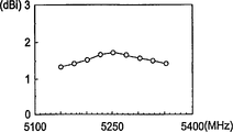
Fig. 5 is according to the double-frequency monodipole of one embodiment of the invention measurement result in the gain of 5.2GHz radio area network system frequency band internal antenna;
Fig. 6 a to Fig. 6 c is the perspective view according to the double-frequency monodipole of other embodiment of this invention.
Symbol description among the figure
1 double-frequency monodipole
11 first horizontal radiation metal wires, 12 second horizontal radiation metal wires
13 vertical radiation metal wires
20 load points, 30 feed-in metal wires
40 microwave base plates
41 first surfaces, 42 second surfaces
50 ground planes
51 breach
611 first horizontal radiation metal wires, 612 second horizontal radiation metal wires
613 vertical radiation metal wires
620 load points, 630 feed-in metal wires
640 microwave base plates
641 first surfaces, 642 second surfaces
650 ground planes
651 breach
Embodiment
Describe the specific embodiment of the present invention in detail below in conjunction with accompanying drawing and preferred embodiment.
As shown in Figure 1, a double frequency antenna of single dipole 1 according to the present invention is printed on a corner of a microwave base plate 40, and this microwave base plate 40 is of a size of 45 * 80mm by one
2The wireless network card circuit board constitute.The printed circuit board (PCB) that this microwave base plate 40 is generally made with glass fiber-reinforced BT (bismaleimide-triazine) resin or FR4 glass reinforced epoxy (fiberglassreinforced epoxy resin), the pliability sheet substrate of can also polyimide (polyimide) making (flexible film substrate).And because this antenna 1 is printed on a corner of this microwave base plate 40, make this antenna 1 occupy this microwave base plate 40 minimum areas, and because the complanation characteristic of this project organization, this antenna 1 has the height conformability with the circuit system of this microwave base plate 40, not only possess the characteristic light, thin, that area is little, also meet the requirement of electronic product volume-diminished now.
With reference to figure 2, double-frequency monodipole 1 according to the present invention mainly comprises: a microwave base plate 40, have a first surface 41 and a second surface 42, one feed-in metal wire 30 is arranged on this first surface 41, this feed-in metal wire 30 is one 50 ohm microstrip, in order to transmitting signals, one first horizontal radiation metal wire 11, be printed on the first surface 41, one second horizontal radiation metal wire 12, be printed on the first surface 41 and be positioned at this first horizontal radiation metal wire 11 times, one vertical radiation metal wire 13, be printed on the first surface 41 and roughly vertical with this second horizontal radiation metal wire 12 with this first horizontal radiation metal wire 11, one load point 20, be positioned on this vertical radiation metal wire 13, this load point 20 is in order to connect this feed-in metal wire 30 and vertical radiation metal wire 13, in order to transmitting signals, an and ground plane 50, be printed on second surface 42, this ground plane 50 is the ground plane of a wireless network card, have a rectangle or near the breach 51 of rectangle, and this antenna 1 is positioned at this rectangle or near directly over the breach 51 of rectangle.Wherein, this first horizontal radiation metal wire 11 is connected near an end of this vertical radiation metal wire 13 or its, this end is positioned at the opposite end of this load point 20, this second horizontal radiation metal wire 12 is connected to the diverse location that this first horizontal radiation metal wire 11 is connected with this vertical radiation metal wire 13, and the openend of this two horizontal radiations metal wire 11,12 extends in the same direction, makes this antenna 1 form a F font.
As previously mentioned, from this load point 20 via the path of vertical radiation metal wire 13 to these first horizontal radiation metal wire, 11 openends, constitute first resonance path of this antenna 1 operation, and determine first (lower) frequency of operation of this antenna 1, in addition, via the path of vertical radiation metal wire 13, constitute second resonance path of antenna 1 operation from this load point 20 to these second horizontal radiation metal wire, 12 openends, and second (higher) frequency of operation of decision antenna 1.When determining dual frequency operation, must consider the correlation of respectively using element compared to prior art, antenna 1 of the present invention, length by this first horizontal radiation metal wire 11 of indivedual adjustment and this second horizontal radiation metal wire 12, can adjust the frequency of this antenna 1 the first two resonance mode easily, reach the desired frequency band of radio area network system.
Fig. 3 to Fig. 5 has shown according to the present invention the actual measured results of the double-frequency monodipole 1 of Figure 1 and Figure 2.Using a relative dielectric constant 4.4, the microwave base plate 40 of thickness 0.8mm, and an area is 10 * 15mm
2Double-frequency monodipole 1, the length of this first horizontal radiation metal wire 11 is 10mm, the length of the second horizontal radiation metal wire 12 is 7mm, the length of vertical radiation metal wire 13 is 15mm, rectangle or be of a size of 15 * 15mm near the breach 51 of rectangle
2Situation under, can get the experimental result of Fig. 3 to Fig. 5.
Figure 3 shows that in 1: 2.5 voltage standing wave ratio or 7.3dB and return under the situation (definition) of loss impedance frequency range, first (lower) the operation mode frequency range that can find out this antenna 1 is 570MHz (2185-2755MHz), second (higher) operation mode frequency range is 280MHz (5115-5395MHz), and its operation frequency range can contain the radio area network system frequency range demand of covering 2.4GHz (2400-2484MHz) and 5.2GHz (5150-5350MHz) two-band.
Operate in gain measurement result in the radio area network system of 2.4GHz and 5.2GHz frequency band respectively for this antenna 1 shown in Fig. 4 and Fig. 5.In the 2.4GHz frequency band, roughly between 1.4 to 2.0dBi, in the 5.2GHz frequency band, antenna gain roughly between 2.3 to 2.7dBi, is presented in first and second operation mode antenna gain, and this antenna 1 all has quite good gain.
Fig. 6 a to Fig. 6 c is depicted as the perspective view of double-frequency monodipole 1 according to other embodiments of the invention.As shown in Fig. 6 a and Fig. 6 b, this first horizontal radiation metal wire 611 is connected near an end of this vertical radiation metal wire 613 or its, this end is positioned at the opposite end of this load point 620, this second horizontal radiation metal wire 612 be connected to the diverse location that this first horizontal radiation metal wire 611 is connected with this vertical radiation metal wire 613, and this two horizontal radiations metal wire 611,612 openend extends in the same direction, compared to antenna shown in Figure 21, this first horizontal radiation metal wire 611 and this second horizontal radiation metal wire 612 can be not exclusively parallel, make this first horizontal radiation metal wire 611, the second horizontal radiation metal wire 612, and the configuration between vertical radiation metal wire 613 threes is more flexible, so the circuit system degree of integration of this antenna 1 and this microwave base plate 640 can improve; And for example shown in Fig. 6 c, this first horizontal radiation metal wire 611 and this also bending downwards of second horizontal radiation metal wire 612, thus it is littler that the area ratio of this antenna 1 shared this microwave base plate 640 is able to, and more can meet the requirement of electronic product volume-diminished.
Aforesaid description and diagram have disclosed preferred embodiment of the present invention, should be regarded as in order to explanation the present invention, but not in order to restriction the present invention.Scope of the present invention should be defined by claims, and contains its legal equivalents, is not limited to previous description.
Claims (9)
Priority Applications (1)
| Application Number | Priority Date | Filing Date | Title |
|---|---|---|---|
| CNB021023972A CN1237659C (en) | 2002-01-24 | 2002-01-24 | Dual Band Single Dipole Antenna |
Applications Claiming Priority (1)
| Application Number | Priority Date | Filing Date | Title |
|---|---|---|---|
| CNB021023972A CN1237659C (en) | 2002-01-24 | 2002-01-24 | Dual Band Single Dipole Antenna |
Publications (2)
| Publication Number | Publication Date |
|---|---|
| CN1434546A CN1434546A (en) | 2003-08-06 |
| CN1237659C true CN1237659C (en) | 2006-01-18 |
Family
ID=27627546
Family Applications (1)
| Application Number | Title | Priority Date | Filing Date |
|---|---|---|---|
| CNB021023972A Expired - Fee Related CN1237659C (en) | 2002-01-24 | 2002-01-24 | Dual Band Single Dipole Antenna |
Country Status (1)
| Country | Link |
|---|---|
| CN (1) | CN1237659C (en) |
Cited By (1)
| Publication number | Priority date | Publication date | Assignee | Title |
|---|---|---|---|---|
| CN102394363A (en) * | 2011-07-11 | 2012-03-28 | 烽火通信科技股份有限公司 | Dual-band monopole antenna |
Families Citing this family (2)
| Publication number | Priority date | Publication date | Assignee | Title |
|---|---|---|---|---|
| US20050099335A1 (en) * | 2003-11-10 | 2005-05-12 | Shyh-Jong Chung | Multiple-frequency antenna structure |
| CN101373855B (en) * | 2007-08-24 | 2013-01-02 | 华硕电脑股份有限公司 | Antenna structure |
-
2002
- 2002-01-24 CN CNB021023972A patent/CN1237659C/en not_active Expired - Fee Related
Cited By (1)
| Publication number | Priority date | Publication date | Assignee | Title |
|---|---|---|---|---|
| CN102394363A (en) * | 2011-07-11 | 2012-03-28 | 烽火通信科技股份有限公司 | Dual-band monopole antenna |
Also Published As
| Publication number | Publication date |
|---|---|
| CN1434546A (en) | 2003-08-06 |
Similar Documents
| Publication | Publication Date | Title |
|---|---|---|
| CN1298078C (en) | Integrated antenna for laptop application | |
| US6650296B2 (en) | Dual-band monopole antenna | |
| CN1235315C (en) | Antenna and electron device containing said antenna | |
| US6747600B2 (en) | Dual-band monopole antenna | |
| CN1251354C (en) | Small size antenna | |
| CN1404291A (en) | Information apparatus including radio communication antenna | |
| CN1836350A (en) | Antenna arrangement and a module and a radio communications apparatus having such an arrangement | |
| CN1897355A (en) | Internal antenna having perpendicular arrangement | |
| CN1455971A (en) | Wireless terminal with multiple antennas | |
| CN1258832C (en) | Wireless communication device with slot antenna | |
| US20030132883A1 (en) | Surface-mountable dual-band monopole antenna for WLAN application | |
| CN1697255A (en) | Multilayer Multiband Antenna | |
| CN1479409A (en) | Dual-frequency dipole antenna | |
| CN1234191C (en) | Dual frequency dual dipole antenna | |
| CN1630133A (en) | Antenna radiator and radio communication device | |
| CN1306654C (en) | Mobile communication terminal built-in antenna | |
| CN1237659C (en) | Dual Band Single Dipole Antenna | |
| CN117673705A (en) | Antenna units and communication equipment | |
| CN212648490U (en) | Dual-band antenna and IOT equipment | |
| CN2577453Y (en) | Dual-band or Tri-band Planar Inverted-F Antenna | |
| CN1190020C (en) | Integrated Dual-Band Printed Single Dipole Antenna | |
| CN1221058C (en) | Dual Band Single Dipole Antenna | |
| CN1697254A (en) | hidden antenna | |
| CN118017192A (en) | Wi-Fi 6E all-metal notebook antenna | |
| CN1855617A (en) | Antenna device |
Legal Events
| Date | Code | Title | Description |
|---|---|---|---|
| C10 | Entry into substantive examination | ||
| SE01 | Entry into force of request for substantive examination | ||
| C06 | Publication | ||
| PB01 | Publication | ||
| C10 | Entry into substantive examination | ||
| SE01 | Entry into force of request for substantive examination | ||
| C14 | Grant of patent or utility model | ||
| GR01 | Patent grant | ||
| CF01 | Termination of patent right due to non-payment of annual fee |
Granted publication date: 20060118 Termination date: 20150124 |
|
| EXPY | Termination of patent right or utility model |