CN1237660A - Thread cutting device in sewing machine - Google Patents
Thread cutting device in sewing machine Download PDFInfo
- Publication number
- CN1237660A CN1237660A CN99106911A CN99106911A CN1237660A CN 1237660 A CN1237660 A CN 1237660A CN 99106911 A CN99106911 A CN 99106911A CN 99106911 A CN99106911 A CN 99106911A CN 1237660 A CN1237660 A CN 1237660A
- Authority
- CN
- China
- Prior art keywords
- line
- cutter
- upper thread
- bonding part
- thread
- Prior art date
- Legal status (The legal status is an assumption and is not a legal conclusion. Google has not performed a legal analysis and makes no representation as to the accuracy of the status listed.)
- Granted
Links
- 238000009958 sewing Methods 0.000 title claims abstract description 38
- 239000004744 fabric Substances 0.000 claims abstract description 7
- 238000010008 shearing Methods 0.000 claims description 6
- 230000000694 effects Effects 0.000 claims description 3
- 238000000034 method Methods 0.000 description 8
- 230000005540 biological transmission Effects 0.000 description 5
- 230000033001 locomotion Effects 0.000 description 5
- 238000000354 decomposition reaction Methods 0.000 description 2
- 238000012423 maintenance Methods 0.000 description 2
- 238000006243 chemical reaction Methods 0.000 description 1
- 238000002485 combustion reaction Methods 0.000 description 1
- 230000013011 mating Effects 0.000 description 1
- 235000012149 noodles Nutrition 0.000 description 1
- 239000007858 starting material Substances 0.000 description 1
- 230000007306 turnover Effects 0.000 description 1
Images


Classifications
-
- D—TEXTILES; PAPER
- D05—SEWING; EMBROIDERING; TUFTING
- D05B—SEWING
- D05B65/00—Devices for severing the needle or lower thread
-
- D—TEXTILES; PAPER
- D05—SEWING; EMBROIDERING; TUFTING
- D05B—SEWING
- D05B65/00—Devices for severing the needle or lower thread
- D05B65/02—Devices for severing the needle or lower thread controlled by the sewing mechanisms
Landscapes
- Engineering & Computer Science (AREA)
- Textile Engineering (AREA)
- Sewing Machines And Sewing (AREA)
Abstract
A thread cutting device is provided in a sewing machine that is operable to form stitches on a fabric using an upper thread and a lower thread. The thread cutting device may include a fixed knife and a movable knife cooperating with each other to cut either one or both of the upper and lower threads. The movable knife may be operable to cut the upper thread at a first timing and to cut the lower thread at a second timing that is different from the first timing.
Description
The present invention relates to the thread cutting device in the Sewing machines, more particularly, relate to a kind of like this thread cutting device, it can optionally be operated with cut-out upper thread (upper thread) and bottom line (Lowerthread), or only cuts off upper thread.
Day, utility model publication number 2-67980 of the present disclosure disclosed a kind of thread cutting device that is used for sewing machine, and it comprises a removable cutter and dead knife, and single or many lines are sheared in two cuttves effects of working in coordination.Still only shear upper thread in order to select upper thread and bottom line to shear all, bottom line declutcher control lever and relevant transmission mechanism thereof are provided.When only having upper thread to cut off, predetermined removable cutter move or rotational time drives declutcher control lever, thereby engage with bottom line and it shifted out the moving line of removable cutter.
But, because declutcher control lever and relevant transmission mechanism thereof combine, need regulate the declutcher control lever operating time, also to carry out maintenance work to declutcher control lever and relevant transmission mechanism thereof.In addition, this design will increase the required component number of shear line.
Therefore, an object of the present invention is to provide an improved thread cutting device.
A kind of thread cutting device that is used for Sewing machines preferably is provided, and wherein a upper thread of use in sewing machine and a foundation line form stitching on fabric.Thread cutting device comprises a dead knife and removable cutter, and one of upper thread and bottom line are cut off in their effects of working in coordination or the both cuts off.Removable cutter can be cut bottom line in second time that is different from the very first time at very first time tangent plane line.
Removable cutter comprises a sheared edge, a upper thread bonding part and a bottom line bonding part.Upper thread bonding part and the bottom line bonding part different position mutually that is placed in.
Preferablely be that removable cutter moves to finish in first moving range and second moving range respectively and engages and shear upper thread and bottom line.First moving range and second moving range can be different.
Other purpose of the present invention, feature and advantage, will be readily appreciated that with claims and after reading following detailed in conjunction with the accompanying drawings.
Fig. 1 is the plane according to the exemplary embodiments of a thread cutting device of the present invention;
Fig. 2 is the front view of Fig. 1;
Fig. 3 (A) is the dead knife of thread cutting device and the view that the decomposition of removable cutter is amplified to 3 (E);
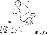
Fig. 4 (A) has shown the enlargement decomposition of cutting the bottom line operation to 4 (E);
Fig. 5 is a time chart, has shown removable cutter operating time and rotating shuttle body (hook), thread take-up tension lever and the relation of sewing needle operating time.
Preferably, be provided for the thread cutter of sewing machine, sewing machine utilizes upper thread and bottom line to exist Form stitching on the fabric. This thread cutter comprises a dead knife and removable cutter, their phases The interworking cooperation is used for cutting cuts one of upper thread and bottom line or both cuts off. Removable cutter can be at first o'clock Between shear upper thread, shear bottom line in second time that is being different from the very first time.
Because upper thread and bottom line can be sheared at different time, in the time only will shearing upper thread, for separating of The declutcher control lever of bottom line will no longer need. In addition, the transmission mechanism that be used for to drive the bottom line declutcher control lever is not yet Needed. Therefore, the timing adjusting operation of declutcher control lever and declutcher control lever and the transmission mechanism that links thereof Maintenance work has not just needed yet. In addition, the component number of thread cutter will reduce.
Preferably, second be pressed for time with the very first time. Therefore, can carry out reliably is to cut off Upper thread and bottom line still only cut off the selection of upper thread. Usually, only cut off the operation of upper thread than on cutting off The operation of lower two kinds of lines is carried out more continually. The result has improved its reliability.
Preferably, removable cutter has a sheared edge, a upper thread bonding part and a bottom line The bonding part. Upper thread bonding part and the bottom line bonding part mutually different position that is placed in.
Removable cutter can be mobile by operation, connects in first moving range and second moving range respectively Merge and shear upper thread and bottom line. First moving range and second moving range are different.
Preferably, first moving range is between a holding fix and first operating position, and second moving range is between the holding fix and second operating position.
Removable cutter allows the upper thread bonding part to engage upper thread at first operating position, and this moment, the rotating shuttle body band of Sewing machines by its upper thread that engages rotation.
Like this, the motion that engages with the upper thread bonding part of upper thread is driven by the rotation of rotating shuttle body.Therefore, the tangent line operation can reliably be carried out, and can not put on the influence of the tension force on the upper thread.The more important thing is that the upper thread part that will cut off of close sewing needle can be separated reliably from the upper thread part of close fabric.Therefore, the operation of the tangent line of upper thread can be carried out reliably, can unexpectedly all not excise upper thread in the part of sewing needle side and the part of fabric side.
Supplementary features that each is above-mentioned and following and method step can utilize respectively or with other features and method steps so that improved thread cutting device and method to be provided, and be used for this type of thread cutting device of design and use.Exemplary of the present invention will elaborate now in conjunction with the accompanying drawings in conjunction with having utilized many this supplementary features and method step.This detailed description only plans to tell those skilled in the art more details, is used to put into practice the better aspect of the technical program, and the scope that is not intended to limit the present invention.Only in claims, define the scope of protection of present invention.Therefore, feature and being combined in of step broadly do not need to put into practice the present invention in following detailed description, and only exemplary of the present invention are described specifically.
Now, provide the detailed description of an exemplary in conjunction with the accompanying drawings.
Fig. 1 is the plane of exemplary embodiments, has shown a thread cutting device and the mechanism of the various Sewing machiness that interrelate with it.
The front view of Fig. 1 is seen Fig. 2.
See that from Fig. 1 and Fig. 2 Sewing machines comprises a shuttle race 10 and a rotating shuttle body 14.Rotating shuttle body 14 comprises that a rotating shuttle (rotating hook) 14a and a shuttle frame (hookholder) 14b form.Rotating shuttle 14a has a hook line end 16 and rotatably is loaded in the shuttle race 10.Rotating shuttle 14a is attached on the rotating shuttle body driving shaft 15, the in succession main shaft (not shown) of Sewing machines of this driving shaft 15, so rotating shuttle 14a can rotate with respect to shuttle frame 14b.Insert a bobbin case 17 in the shuttle frame 14b, a peg or spindle (not shown) is equipped with in its inside.One foundation line T2 is round peg or spindle, and this will be in following detailed explanation.A reciprocating sewing needle (not shown) passes pin hole 12 (as Fig. 3) turnover rotating shuttle body 14.Pin hole 12 is positioned on the needle plate (not shown), and needle plate is installed on above the rotating shuttle body 14 of shuttle race 10.The upper thread T1 and the bottom line T2 that are provided by sewing needle and peg or spindle respectively are provided, and sewing needle and the mating reaction of rotating shuttle body form stitching on fabric.A thread take-up tension lever (not shown) helps picking upper thread T1 to respond the operation of rotating shuttle body 14 and sewing needle.Sewing mechanism comprises that resembling sewing needle, rotating shuttle body and thread take-up tension lever is that the present technique field is known, therefore will no longer describe in detail.
Thread cutting device preferably includes a dead knife 20 and removable cutter 30.Dead knife 20 is installed in (see figure 1) on the tool rest 18 by screw 21.Tool rest 18 also is installed on the shuttle race 10.Removable cutter 30 is installed in the upper end of cutter shaft 40.As shown in Figure 2, cutter shaft 40 is rotatably mounted and extend to a position of shuttle race 10 belows vertically downward from removable cutter 30 by shuttle race 10.Drive link 52 is connected in the lower end of cutter shaft 40.
A L type carriage 44 has been fixed on the right side of shuttle race 10 (as Fig. 2).Motor 42 vertically is installed on the carriage 44, as the power source of mobile cutter 30.Motor 42 has an output shaft 46, extends downwards from motor 42, passes the horizontal component of carriage 44.Drive rod 48 is fixed on the output shaft 46, and connects drive link 52 by connecting rod 50.As a result, the rotation of motor 42 changes into the crankmotion of cutter shaft 40 by drive rod 48, connecting rod 50 and drive link 52.Therefore, removable cutter 30 is done toward the rotation of after-combustion pivot around the axis of cutter shaft 40 with cutter shaft 40.
As shown in Figure 3, dead knife 20 has preferred a setting with removable cutter 30, and wherein the front end of dead knife 20 comprises a sheared edge 22 at its downside.The front end of removable cutter 30 has a upper thread engagement recesses 36 and a bottom line engagement recesses 38.Described upper thread engagement recesses 36 is in the front end of removable cutter 30 in the relative both sides of pivotal orientation with bottom line engagement recesses 38.Upper thread engagement recesses 36 is passed through slit 34 opening laterally.Sheared edge 39 is in upper thread engagement recesses 36 side in the counterclockwise direction, shown in Fig. 3 (A).Sheared edge 39 cooperates tangent line to explain below with sheared edge 22 on the dead knife 20.Bottom line engagement recesses 38 is V-shaped basically in plane.Closed angle end 32 is positioned at removable cutter front end in upper thread engagement recesses 36 sides.This closed angle end points to shown in Fig. 3 (A) counterclockwise.Guide edge 37 is connecting closed angle end 32 and bottom line engagement recesses 38.
Controller (not shown) output control signal is given motor 42, is used for controlling the motion of removable cutter 30.
Set forth the recommendation operation of an above thread cutting device exemplary embodiments now.
Fig. 3 (A) shows the preferred operation of cutting off upper thread T1 to 3 (E).In order to shear upper thread T1 in the sewing process, controller gives control signal of motor 42 outputs so that starter.Sewing operation carries out with a method of knowing by rotating shuttle body 14 or rotating shuttle 14a and reciprocating sewing needle cooperation.When motor 42 rotations, removable cutter 30 is turned back to first operating position shown in Fig. 3 (B) from the holding fix shown in Fig. 3 (A).When the selection of time that removable cutter 30 moves arrives the close position of pin hole 12 at the closed angle end 32 of removable cutter 30, as Fig. 3 (B), before the hook line end 16 of rotating shuttle 14a engages upper thread T1.In order to illustrate, bottom line T2 does not show to 3 (E) at Fig. 3 (A).
When rotating shuttle body 14 rotation, upper thread T1 moves to rotating shuttle body 14 the insides along the hypotenuse of hook line end 16, shown in Fig. 3 (D), and is compelled to pass slit 34 and enters upper thread engagement recesses 36, shown in Fig. 3 (E).
Controller gives motor 42 outputs a signal then, makes removable cutter 30 get back to holding fix from first operating position, substantially at synchronization thread take-up tension lever pull-up upper thread T1.In the gyration process, the upper thread engagement recesses 36 of removable cutter 30 moves on to above the sheared edge 22 of dead knife 20, so that the sheared edge of removable cutter 30 39 is cut off upper thread T1 with sheared edge 22 cooperations of dead knife 20.
Fig. 4 (A) has shown a preferred operation that is used to cut off bottom line T2 to 4 (E).In order to shear bottom line T2, controller gives motor 42 outputs a control signal, rotates removable cutter 30 and makes it from holding fix through first operating position to second operating position.Fig. 4 (A) shown removable cutter 30 first operating position of upper thread shearing manipulation be one suddenly between the position.Like this, removable cutter 30 turns over from first operating position.
When removable cutter 30 when first operating position is moved further, guide edge 37 engages with bottom line T2, and shown in Fig. 4 (B), overcome the tension force on the bottom line T2, bottom line T2 is shifted out the mobile alignment of guide edge 37, when removable cutter 30 reached second operating position shown in Fig. 4 (C), bottom line T2 broke away from from removable cutter 30, makes bottom line T2 reply initial position.
Then, controller makes removable cutter 30 turn back to holding fix from second operating position to signal of motor 42 outputs.As a result, bottom line T2 is engaged by bottom line engagement recesses 38, as Fig. 4 (D) and 4 (E), shears by sheared edge 22 cooperations of sheared edge 39 and dead knife 20.
Fig. 5 has shown the hook line end 16 of removable 30 operating times of cutter and rotating shuttle body 14, the relation of the operating time of thread take-up tension lever and sewing needle.For removable cutter 30, thread take-up tension lever and sewing needle, the ordinate of Fig. 5 are represented the traverse position of these elements.For hook line end 16, the ordinate of Fig. 5 is represented the upright position of hook line end 16 with respect to the reference position.The abscissa of Fig. 5 is represented the rotational angle of machine spindle, main shaft driven in synchronism rotating shuttle body 14, thread take-up tension lever and sewing needle.
Line X, Y and Z represent hook line end 16 respectively, the operating time of thread take-up tension lever and sewing needle.Line of motion when line m represents that removable cutter 30 is only sheared upper thread T1.Line of motion when line n represents that removable cutter is all sheared upper thread T1 and bottom line T2.
Time P is the time that upper thread hook line end 16 engages.As previously mentioned, removable cutter 30 begin to move to first operating position from holding fix will be early than time P.Removable cutter 30 returns from time Q holding fix since first operating position.Time Q represents that thread take-up tension lever begins to go up the time of hand-pulled noodles line T1.After upper thread T1 was sheared, a part divided the upper thread of being cut to continue to stretch out from sewing needle.Remaining quilt is cut partial-length and is changed with removable cutter 30 times of return variation.Therefore, the remaining length of being cut part is dragged overtime and is shortened when time of return.
As shown in Figure 5, the operation cycle of removable cutter cut-out bottom line is different from the operation cycle of cutting off upper thread.Therefore, when upper thread T1 and bottom line T2 will shear, the shearing manipulation of bottom line T2 carried out the back in the shearing manipulation of upper thread T1, shown in lines n.Time R is the time that Sewing machines or its main shaft stop.For sewing needle, in case when removable cutter 30 will be sheared bottom line T2, sewing needle broke away from from main shaft, so that be in the extreme higher position.
Because removable cutter 30 is by motor 42 drivings and irrelevant with main shaft, so still can carry out the bottom line shearing manipulation after the main shaft stall.
Though in above preferred embodiment, removable cutter 30 moves pivotally, removable cutter 30 also can carry out different moving, and for example carries out linear movement by means of suitable slide mechanism.In addition, a kind of cam mechanism of the main shaft drives by Sewing machines can substitute motor 42.
Though thread cutting device is only sheared the operation that upper thread T1 or upper thread T1 and bottom line T2 shear in the typical preferred embodiment of Miao Shuing in the above, this thread cutting device also can only be sheared bottom line T2.For example, if making a kind of different color relation into, bottom line T2 can only shear bottom line T2.
Claims (12)
1. the thread cutting device of Sewing machines, described use in sewing machine is in utilizing upper thread and bottom line to form stitching on fabric, and described device comprises:
Dead knife and one is removable cutter, and their effects of being fitted to each other are sheared one of upper thread and bottom line or sheared all,
Described removable cutter is sheared upper thread in the very first time and is sheared bottom line in second time that is different from the very first time.
2. thread cutting device as claimed in claim 1 is characterized in that, described second time is by after the described very first time.
3. thread cutting device as claimed in claim 1 is characterized in that, described removable cutter comprises a sheared edge, a upper thread bonding part and a bottom line bonding part, described upper thread bonding part and bottom line bonding part diverse location that is placed in.
4. thread cutting device as claimed in claim 1 is characterized in that, described removable cutter moves in first moving range and second moving range so that engage and shearing upper thread and bottom line respectively, and described first moving range and described second moving range are different.
5. thread cutting device as claimed in claim 4 is characterized in that, described first moving range is between a holding fix and one first operating position, and described second moving range is between the described holding fix and second operating position.
6. thread cutting device as claimed in claim 5, it is characterized in that, described removable cutter comprises a sheared edge, a upper thread bonding part and a bottom line bonding part, described removable cutter allows the upper thread bonding part to engage upper thread at described first operating position, and the rotating shuttle body of Sewing machines drove its upper thread that engages and rotated together this moment.
7. be used to shear the equipment of single line and second line, comprise:
First cutter;
The second cutter that moves with respect to first cutter;
A controller;
The order that described second cutter responds described controller is moved, and described controller sends first order at least and shears single line, sends second order then and shears second line.
8. equipment as claimed in claim 7 is characterized in that, described first order of sending will be prior to second order.
9. equipment as claimed in claim 8 is characterized in that, described second cutter is sheared single line and shear second line in second moving range in first moving range.
10. equipment as claimed in claim 9 is characterized in that, between the second place, and described second moving range is between above-mentioned primary importance to the three positions a primary importance for described first moving range.
11. equipment as claimed in claim 10, it is characterized in that, described second cutter has a sheared edge, one first line bonding part and one second line bonding part, the described first line bonding part engages with single line in the described second place, and the second line bonding part engages with second line in the 3rd position.
12. a Sewing machines, the motor that it comprises the equipment of claim 11 and is used to drive described second cutter.
Applications Claiming Priority (3)
| Application Number | Priority Date | Filing Date | Title |
|---|---|---|---|
| JP10147601A JPH11333175A (en) | 1998-05-28 | 1998-05-28 | Thread cutting device of sewing machine |
| JP147601/1998 | 1998-05-28 | ||
| JP147601/98 | 1998-05-28 |
Publications (2)
| Publication Number | Publication Date |
|---|---|
| CN1237660A true CN1237660A (en) | 1999-12-08 |
| CN1108408C CN1108408C (en) | 2003-05-14 |
Family
ID=15434033
Family Applications (1)
| Application Number | Title | Priority Date | Filing Date |
|---|---|---|---|
| CN99106911A Expired - Fee Related CN1108408C (en) | 1998-05-28 | 1999-05-28 | Thread cutting device in sewing machine |
Country Status (5)
| Country | Link |
|---|---|
| US (1) | US6152058A (en) |
| JP (1) | JPH11333175A (en) |
| KR (1) | KR100539902B1 (en) |
| CN (1) | CN1108408C (en) |
| DE (1) | DE19925013C2 (en) |
Cited By (4)
| Publication number | Priority date | Publication date | Assignee | Title |
|---|---|---|---|---|
| CN102234880A (en) * | 2010-04-28 | 2011-11-09 | 兄弟工业株式会社 | Sewing machine |
| CN101381932B (en) * | 2007-09-05 | 2013-03-20 | 兄弟工业株式会社 | Thread cutting apparatus for sewing machine |
| CN112481851A (en) * | 2020-12-10 | 2021-03-12 | 温州瓯燕电脑刺绣有限公司 | Thread cutting device of embroidery machine |
| CN119980585A (en) * | 2025-03-14 | 2025-05-13 | 杰克科技股份有限公司 | Movable thread cutter with thread sweeping function, thread cutting mechanism and sewing machine |
Families Citing this family (2)
| Publication number | Priority date | Publication date | Assignee | Title |
|---|---|---|---|---|
| JP5318320B2 (en) * | 2005-06-30 | 2013-10-16 | 蛇の目ミシン工業株式会社 | Automatic thread trimming machine |
| JP7508006B2 (en) * | 2020-01-29 | 2024-07-01 | 株式会社ジャノメ | sewing machine |
Family Cites Families (10)
| Publication number | Priority date | Publication date | Assignee | Title |
|---|---|---|---|---|
| US3424116A (en) * | 1965-08-25 | 1969-01-28 | Union Special Maschinenfab | Thread cutoff device for lockstitch sewing machines |
| DE2015757A1 (en) * | 1970-04-02 | 1971-10-21 | Fa. Werner, Keilmann, 6143 Lorsch | Yarn trapper for sewing machine yarn cutter |
| US4077342A (en) * | 1975-12-15 | 1978-03-07 | Union Special Corporation | Thread trimming mechanism for sewing machines |
| DE3208159C2 (en) * | 1982-03-06 | 1984-03-01 | Pfaff Industriemaschinen Gmbh, 6750 Kaiserslautern | Thread cutting device on lockstitch sewing machines |
| US4630559A (en) * | 1984-11-08 | 1986-12-23 | Tokyo Juki Industrial Co., Ltd. | Thread cutting mechanism in lock stitch sewing machine |
| JPH0267980A (en) * | 1988-09-02 | 1990-03-07 | Fujitsu Ltd | Circuit for detecting charged state in battery |
| US5131340A (en) * | 1989-06-09 | 1992-07-21 | Tokai Kogyo Mishin Kabushiki Kaisha | Selective thread cutting device in a sewing machine |
| CN1054412C (en) * | 1995-03-28 | 2000-07-12 | 重机公司 | Thread trimmer for twin-needle sewing machines |
| JPH0975575A (en) * | 1995-09-13 | 1997-03-25 | Tokai Ind Sewing Mach Co Ltd | Thread cutting device of sewing machine |
| DE19722395C1 (en) * | 1997-05-28 | 1998-08-06 | Pfaff Ag G M | Double lock:stitch sewing machine thread cutter |
-
1998
- 1998-05-28 JP JP10147601A patent/JPH11333175A/en not_active Withdrawn
-
1999
- 1999-05-25 DE DE19925013A patent/DE19925013C2/en not_active Expired - Fee Related
- 1999-05-25 KR KR10-1999-0018770A patent/KR100539902B1/en not_active Expired - Fee Related
- 1999-05-26 US US09/318,607 patent/US6152058A/en not_active Expired - Fee Related
- 1999-05-28 CN CN99106911A patent/CN1108408C/en not_active Expired - Fee Related
Cited By (6)
| Publication number | Priority date | Publication date | Assignee | Title |
|---|---|---|---|---|
| CN101381932B (en) * | 2007-09-05 | 2013-03-20 | 兄弟工业株式会社 | Thread cutting apparatus for sewing machine |
| CN102234880A (en) * | 2010-04-28 | 2011-11-09 | 兄弟工业株式会社 | Sewing machine |
| CN102234880B (en) * | 2010-04-28 | 2013-02-13 | 兄弟工业株式会社 | Sewing machine |
| CN112481851A (en) * | 2020-12-10 | 2021-03-12 | 温州瓯燕电脑刺绣有限公司 | Thread cutting device of embroidery machine |
| CN119980585A (en) * | 2025-03-14 | 2025-05-13 | 杰克科技股份有限公司 | Movable thread cutter with thread sweeping function, thread cutting mechanism and sewing machine |
| CN119980585B (en) * | 2025-03-14 | 2026-04-24 | 杰克科技股份有限公司 | A movable thread cutter with a thread-sweeping function, a thread-cutting mechanism, and a sewing machine. |
Also Published As
| Publication number | Publication date |
|---|---|
| KR100539902B1 (en) | 2005-12-28 |
| DE19925013A1 (en) | 1999-12-02 |
| KR19990088526A (en) | 1999-12-27 |
| DE19925013C2 (en) | 2001-12-13 |
| US6152058A (en) | 2000-11-28 |
| JPH11333175A (en) | 1999-12-07 |
| CN1108408C (en) | 2003-05-14 |
Similar Documents
| Publication | Publication Date | Title |
|---|---|---|
| US4867082A (en) | Electronic device for autosetting control in industrial sewing machines | |
| JP2017184980A (en) | sewing machine | |
| CN1109785C (en) | Buttonhole machine | |
| CN1063809C (en) | Sewing machine, in particular buttonhole sewing machine, with thread clamp and cutter | |
| CN1108408C (en) | Thread cutting device in sewing machine | |
| CN101831768B (en) | Thread cutting device for sewing machine | |
| US10982366B2 (en) | Sewing machine | |
| CN100365188C (en) | Sewing machine, especially buttonhole-lockstitching sewing machine, with string fastening and cutting device | |
| EP4361334B1 (en) | Thread cutting apparatus and automatic stitching apparatus | |
| US6070540A (en) | Holing sewing machine | |
| US5623887A (en) | Thread cutting device in sewing machine | |
| CN1307335C (en) | Sewing machine with needle feed | |
| KR101757919B1 (en) | Sewing Machine | |
| KR20020038539A (en) | Sequining Head | |
| CN100432318C (en) | Bottom thread cutting device for buttonhole sewing machine and buttonhole sewing machine | |
| JP2000262779A (en) | Stitching method of staggered sewing machine and staggered sewing machine | |
| CN2737813Y (en) | Device for severing the thread used on button holing machine | |
| KR101471985B1 (en) | Grooming machine of sewing machine | |
| CN222226762U (en) | Scissors device of flat knitting machine | |
| CN1110591C (en) | Control device for sewing machine | |
| CN109868574B (en) | Double-acting knife thread cutting device and method for sewing machine | |
| CN1940163B (en) | Pocket mouth pipe edges sewing machine | |
| JP4642545B2 (en) | Thread trimmer | |
| JP2001096084A (en) | Hole sewing machine | |
| JP2732132B2 (en) | Sewing machine thread cutting device |
Legal Events
| Date | Code | Title | Description |
|---|---|---|---|
| C06 | Publication | ||
| PB01 | Publication | ||
| C10 | Entry into substantive examination | ||
| SE01 | Entry into force of request for substantive examination | ||
| C14 | Grant of patent or utility model | ||
| GR01 | Patent grant | ||
| C17 | Cessation of patent right | ||
| CF01 | Termination of patent right due to non-payment of annual fee |
Granted publication date: 20030514 |