CN1237772A - Variable condenser - Google Patents
Variable condenser Download PDFInfo
- Publication number
- CN1237772A CN1237772A CN99102855A CN99102855A CN1237772A CN 1237772 A CN1237772 A CN 1237772A CN 99102855 A CN99102855 A CN 99102855A CN 99102855 A CN99102855 A CN 99102855A CN 1237772 A CN1237772 A CN 1237772A
- Authority
- CN
- China
- Prior art keywords
- stator
- rotor
- variable capacitor
- capacitor according
- cover
- Prior art date
- Legal status (The legal status is an assumption and is not a legal conclusion. Google has not performed a legal analysis and makes no representation as to the accuracy of the status listed.)
- Granted
Links
- 238000004381 surface treatment Methods 0.000 claims abstract description 61
- 239000002184 metal Substances 0.000 claims abstract description 28
- 229910052751 metal Inorganic materials 0.000 claims abstract description 28
- 229910001220 stainless steel Inorganic materials 0.000 claims abstract description 13
- 239000010935 stainless steel Substances 0.000 claims abstract description 13
- BQCADISMDOOEFD-UHFFFAOYSA-N Silver Chemical compound [Ag] BQCADISMDOOEFD-UHFFFAOYSA-N 0.000 claims abstract description 11
- ATJFFYVFTNAWJD-UHFFFAOYSA-N Tin Chemical compound [Sn] ATJFFYVFTNAWJD-UHFFFAOYSA-N 0.000 claims abstract description 11
- PCHJSUWPFVWCPO-UHFFFAOYSA-N gold Chemical compound [Au] PCHJSUWPFVWCPO-UHFFFAOYSA-N 0.000 claims abstract description 11
- 229910052737 gold Inorganic materials 0.000 claims abstract description 11
- 239000010931 gold Substances 0.000 claims abstract description 11
- 229910052709 silver Inorganic materials 0.000 claims abstract description 11
- 239000004332 silver Substances 0.000 claims abstract description 11
- 239000011135 tin Substances 0.000 claims abstract description 11
- 229910052718 tin Inorganic materials 0.000 claims abstract description 11
- 230000000087 stabilizing effect Effects 0.000 claims abstract description 8
- 238000009713 electroplating Methods 0.000 claims abstract description 6
- 239000003990 capacitor Substances 0.000 claims description 68
- 239000004020 conductor Substances 0.000 claims description 17
- 238000000034 method Methods 0.000 claims description 9
- 230000008569 process Effects 0.000 claims description 8
- 230000009471 action Effects 0.000 claims description 4
- 230000008859 change Effects 0.000 claims description 4
- 230000000694 effects Effects 0.000 abstract description 2
- 229910000679 solder Inorganic materials 0.000 description 13
- 238000005476 soldering Methods 0.000 description 8
- 238000007747 plating Methods 0.000 description 6
- 235000014676 Phragmites communis Nutrition 0.000 description 4
- 238000009434 installation Methods 0.000 description 3
- 239000000919 ceramic Substances 0.000 description 2
- 230000007613 environmental effect Effects 0.000 description 2
- 239000000463 material Substances 0.000 description 2
- 150000002739 metals Chemical class 0.000 description 2
- 230000004308 accommodation Effects 0.000 description 1
- PNEYBMLMFCGWSK-UHFFFAOYSA-N aluminium oxide Inorganic materials [O-2].[O-2].[O-2].[Al+3].[Al+3] PNEYBMLMFCGWSK-UHFFFAOYSA-N 0.000 description 1
- 238000010276 construction Methods 0.000 description 1
- 238000005516 engineering process Methods 0.000 description 1
- 230000006872 improvement Effects 0.000 description 1
- 239000012212 insulator Substances 0.000 description 1
- 239000007769 metal material Substances 0.000 description 1
Images


Classifications
-
- H—ELECTRICITY
- H01—ELECTRIC ELEMENTS
- H01G—CAPACITORS; CAPACITORS, RECTIFIERS, DETECTORS, SWITCHING DEVICES, LIGHT-SENSITIVE OR TEMPERATURE-SENSITIVE DEVICES OF THE ELECTROLYTIC TYPE
- H01G5/00—Capacitors in which the capacitance is varied by mechanical means, e.g. by turning a shaft; Processes of their manufacture
- H01G5/04—Capacitors in which the capacitance is varied by mechanical means, e.g. by turning a shaft; Processes of their manufacture using variation of effective area of electrode
- H01G5/06—Capacitors in which the capacitance is varied by mechanical means, e.g. by turning a shaft; Processes of their manufacture using variation of effective area of electrode due to rotation of flat or substantially flat electrodes
Landscapes
- Engineering & Computer Science (AREA)
- Power Engineering (AREA)
- Microelectronics & Electronic Packaging (AREA)
- Fixed Capacitors And Capacitor Manufacturing Machines (AREA)
Abstract
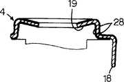
由金属构成的转子或在转子上装配的弹簧垫片,在其内侧底面有电气接触的状态下,转子相对于定于转动。上述转子、定子收容在盖子下面,由于弹簧片的作用,转子受压力和定子接触。如使用弹性好的不锈钢,因不锈钢表面的接触阻抗较大,盖子的内侧底面和转子或弹簧垫片的接触阻抗就变大。在盖子4的内侧底面19上,通过电镀如金、锡或银,实施减小接触阻抗、稳定表面的表面处理21。在和盖子4形成一体的转子引线18处,最好实施表面处理22。

The rotor made of metal or the spring washer assembled on the rotor rotates relative to the fixed position when the inner bottom surface is in electrical contact. The above-mentioned rotor and stator are accommodated under the cover, and due to the effect of the leaf spring, the rotor is under pressure and contacts the stator. If stainless steel with good elasticity is used, since the contact resistance of the stainless steel surface is relatively large, the contact resistance between the inner bottom surface of the cover and the rotor or spring washer becomes large. On the inner bottom surface 19 of the cover 4, a surface treatment 21 for reducing contact resistance and stabilizing the surface is carried out by electroplating such as gold, tin or silver. At the rotor leads 18 which are integral with the cover 4, a surface treatment 22 is preferably applied.
Description
本发明涉及可变电容器、尤其涉及通过转动和定子电极相对应的转子电极来改变定子电极与转子电极之间的有效相对应面积,实现改变可变电容器的静电容量的可变电容器。The invention relates to a variable capacitor, in particular to a variable capacitor that changes the effective corresponding area between the stator electrode and the rotor electrode by rotating the rotor electrode corresponding to the stator electrode to realize the change of the electrostatic capacity of the variable capacitor.
本发明所涉及的感兴趣的可变电容器,例如,在专利公开平成6-120079号公报中有记载。图1及图2所示为该公报中记载的可变电容器1。其中,在图1中,(1)为可变电容器1的俯视图、(2)为主视图、(3)为右侧视图、(4)为仰视图,图2为图1(1)中沿A-A线的剖面图。Interesting variable capacitors related to the present invention are described in, for example, Japanese Patent Publication No. Heisei 6-120079. 1 and 2 show a
参照图1和图2,可变电容器1,大体可拆为定子2、转子3以及盖子4。定子2的主要部分由陶瓷电介质构成。转子3由黄铜类金属构成。盖子4由诸如不锈钢的弹性金属构成。Referring to FIG. 1 and FIG. 2 , the
下面,对上述各主要部件的详细构造加以说明。Next, the detailed structure of each of the above-mentioned main components will be described.
定子2在总体上具备对称的构造。在定子2的内部,排列有定子电极5和定子电极6。为了使定子电极5和定子电极6互相之间实现电气连接,在定子2的各顶端部的外表面上,由导电膜形成定子接头7和8。The
这样,由2个定子电极5和6以及2个定子接头7和8构成的定子2具备对称性,对于由这样的定子2组装的可变电容器1,可以不用考虑定子2的方向。因此,如果不特别要求这个特点,定子电极5和6的任何一方以及与之相关联的定子接头7和8的任何一方可以被省略。In this way, the
在定子2的下面,在相对的两端边缘向内的方向上形成有伸展的凹陷部分9和10。On the underside of the
转子3,装配在上述定子2的上面,在其下面,形成有具备突出顶端部分的类似半圆形状的转子电极11。此外,在转子3的下面,形成有与转子电极11相同高度的凸出部12,是为了防止因转子电极11的存在造成转子3的倾斜。The
在转子3上,形成有螺丝刀沟槽13,用于插入螺丝刀等工具实施转动操作。On the
盖子4,用于收纳转子3,并且用于固定定子2。借助于盖子4,可保证转子3和定子2之间的相对转动。在盖子4上,形成有调整用孔穴14,使转子3的螺丝刀沟槽露出,这样就可以插入螺丝刀等工具来转动转子3。The
在调整用孔穴14的周围,设计有簧片作用部15,和转子3相接触,使得转子3与定子2相对施压接触。簧片作用部15,处于调整用孔穴14的周围,具有在中心部分向下方倾斜的形状,由调整用孔穴14周围的金属材料自身构成。Around the
在盖子4的下方方向设计有一体的固定片16和17,它们处于相对的方向。固定片16和17,分别用于固定在定子2的下面形成的凹陷部分9和10,因此其后端是弯曲成折叠状的。There are integral fixing pieces 16 and 17 designed in the lower direction of the
另外,在盖子4上,在与固定片16和17相错的位置下方沿定子2的长度方向,设计有转子接头18。In addition, on the
此外,在与簧片作用部15的下面一侧相对的盖子4的内侧底面19和转子3之间,装配有导电性弹簧垫片20。弹簧垫片20沿厚度方向的变形不超出其弹性范围。In addition, a
这样,由定子2、转子3、盖子4以及弹簧垫片20以下面的方式就可组装成可变电容器1。In this way, the
在定子2的上面装配转子3、在转子3的上面装配弹簧垫片20、装配盖子4用以覆盖转子3和弹簧垫片20。然后,为了使转子3和定子2相互施压接触,将盖子4沿定子2的方向压住,同时将设计在盖子4上的固定片16和17的端部分别向内侧方向弯曲、折叠。这样,固定片16和17就分别和在定子2的下面形成的凹陷部分9和10固定在一起。The
这样,设计在盖子4上的转子接头18和设计在定子2上的定子接头8(在图中状态下,定子接头没有发挥其功能)处于相对的位置。因而,在转子接头18与定子接头8之间用焊锡(在图中没有表示出)相连,一方面使盖子4相对于定子2的固定状态加以强化,又能是定子接头8发挥转子接头的功能。In this way, the
这样,就完成了可变电容器1的组装。In this way, the assembly of the
在这种组装状态下,如图2所示,转子电极11,相对于定子电极5,通过构成定子2的陶瓷电介质的一部分,形成静电电容。转动转子3,改变转子电极11和定子电极5之间的有效相对面积,静电容量就会发生变化。该静电电容量,可以通过与定子电极5相连接的定子接头7、以及转子接头18之间获得。其中,设计在盖子4上的转子接头18通过弹簧垫片20和由转子3形成的转子电极11实现电气连接。In this assembled state, as shown in FIG. 2 , the
然而,上述可变电容器1存在着以下需要解决的问题。However, the above-described
为了获得静电电容量,由形成转子接头18的盖子4开始,到形成转子电极11的转子3为止的电气连接线路的一部分中,盖子4的内侧底面19和弹簧垫片20有相接触的部分。此外,如上所述,盖子4应具备弹性,有代表性的盖子由不锈钢构成。In order to obtain the electrostatic capacitance, the
因不锈钢表面具有较大的接触阻抗,表面也不稳定,这样,盖子4的内侧底面19和弹簧垫片20之间导电的可靠性就存在问题。Because the stainless steel surface has a large contact resistance, the surface is also unstable, so there is a problem in the reliability of the conduction between the
另外,不锈钢表面的焊锡可焊性差,与盖子4一体形成的转子接头18的焊锡可焊性就差。因此,该可变电容器1在线路板(在图中没有表示出来)上装配时,很难实施锡焊,存在装配的可靠性问题。In addition, the solderability of the stainless steel surface is poor, as is the solderability of the
因此,本发明的目的,就是提供一种可变电容器以解决上述问题。Therefore, the purpose of the present invention is to provide a variable capacitor to solve the above problems.
本发明所涉及的可变电容器,具备定子,包括定子电极以及与上述定子电极电气接触的定子接头;具备转子,其形成的电极和上述定子电极通过电介质相对应;具备导电盖子,和上述转子电极相连接,为了实现改变上述转子电极和上述定子电极之间的有效相对面积,该盖子具备一定的容纳形状使得上述转子可以相对上述定子转动,并用于固定上述定子;上述盖子由具备接触阻抗较大表面的金属构成;上述盖子和上述转子电极的电气连接线路,包括上述盖子的内侧底面和上述转子进行电气连接的导体相接触的部分。The variable capacitor according to the present invention includes a stator including stator electrodes and stator joints electrically contacting the stator electrodes; a rotor having electrodes corresponding to the stator electrodes through a dielectric; a conductive cover and the rotor electrodes In order to change the effective relative area between the rotor electrodes and the stator electrodes, the cover has a certain shape so that the rotor can rotate relative to the stator and is used to fix the stator; the cover has a large contact resistance The metal structure of the surface; the electrical connection line between the cover and the rotor electrode, including the part where the inner bottom surface of the cover is in contact with the conductor for electrical connection of the rotor.
在本发明中,对于上述可变电容器,为了解决上述技术上的课题,起码要在上述盖子的内侧底面,实施表面处理以减小接触阻抗、稳定表面。在本发明中,构成盖子的金属,例如是不锈钢的情况下,不但表面具有较大的接触阻抗,而且表面的锡焊可焊性也差。这样,构成盖子的金属表面锡焊可焊性差,在盖子与转子接头一体形成的情况下,起码应该在转子接头处,实施表面处理以改善锡焊焊接性。In the present invention, in order to solve the technical problems described above, at least the inner bottom surface of the cover is subjected to surface treatment to reduce contact resistance and stabilize the surface of the variable capacitor. In the present invention, when the metal constituting the cover is, for example, stainless steel, the surface not only has a large contact resistance, but also has poor solderability on the surface. In this way, the solderability of the metal surface constituting the cover is poor. In the case where the cover is integrally formed with the rotor joint, at least the rotor joint should be surface treated to improve the solderability.
另外,对于上述情况,转子接头是在沿定子长度方向,用于改善锡焊可焊接性的表面处理,更希望仅在转子接头的外侧一面实施。In addition, for the above situation, the rotor joint is along the length direction of the stator, and the surface treatment for improving the solderability of the soldering is more desirable to be carried out only on the outer side of the rotor joint.
在实施例上,希望上述用于减小接触阻抗、稳定表面的表面处理和上述用于改善锡焊焊接性的表面处理是同一表面处理工艺,例如,金、锡或银的电镀就是这样的表面处理工艺。In an embodiment, it is desirable that the above-mentioned surface treatment for reducing contact resistance and stabilizing the surface and the above-mentioned surface treatment for improving solderability are the same surface treatment process, for example, gold, tin or silver plating is such a surface Processing technology.
对本发明所涉及的可变电容器,最好在盖子上形成调整用孔穴用于插入转动上述转子的工具,同时在上述调整用孔穴的周围设计有弹簧片作用部,将转子压向定子,使得上述转子和上述定子相互接触。For the variable capacitor involved in the present invention, it is preferable to form an adjustment hole on the cover for inserting a tool for rotating the above-mentioned rotor, and at the same time, a spring leaf action part is designed around the above-mentioned adjustment hole to press the rotor to the stator, so that the above-mentioned The rotor and the aforementioned stator are in contact with each other.
此外,在所希望实施例中,转子由导电性金属构成,转子本身就是上述电路的一部分。在这种情况下,在有的实施例中,与盖子的内侧底面相接触的上述导体,就构成转子。Furthermore, in a desired embodiment, the rotor is constructed of a conductive metal, the rotor itself being part of the electrical circuit described above. In this case, in some embodiments, the above-mentioned conductors in contact with the inner bottom surface of the cover constitute the rotor.
在所希望实施例中,在盖子的内侧底面与转子之间,装配有导电性弹簧垫片。在这种情况下,与盖子的内侧底面相接触的上述导体,就是该弹簧垫片。In a desired embodiment, a conductive spring washer is fitted between the inner bottom surface of the cover and the rotor. In this case, the above-mentioned conductor which is in contact with the inner bottom surface of the cover is the spring washer.
下面简单说明附图The following is a brief description of the accompanying drawings
图1表示本发明的一种实施例中可变电容器1的外观,(1)是俯视图、(2)是主视图、(3)是右侧视图、(4)是仰视图。1 shows the appearance of a
图2是沿图1(1)中A-A线的剖面图。Fig. 2 is a sectional view along line A-A in Fig. 1(1).
图3表示在图2中所示盖子4上实施表面处理的方式的剖面图。FIG. 3 shows a sectional view of the manner in which the surface treatment is carried out on the
图4是相对应于图2的剖面图,显示了可变电容器1安装在线路板23上的状态。FIG. 4 is a sectional view corresponding to FIG. 2, showing a state in which the
图5是相对应于图3的图示,显示了在盖子4上实施表面处理的其他方式。FIG. 5 is a representation corresponding to FIG. 3 , showing a further way of carrying out the surface treatment on the
图6是相对应于图4的图示,可变电容器1处于在线路板23上的安装状态,显示焊锡24浸入了所不希望浸入的部分。FIG. 6 is an illustration corresponding to FIG. 4 , the
图7是相对应于图3的图示,显示了在盖子4上实施表面处理的另外其他方式。FIG. 7 is a representation corresponding to FIG. 3 , showing yet another way of implementing a surface treatment on the
图8是相对应于图3的图示,显示了在盖子4上实施表面处理的另外其他方式。FIG. 8 is a representation corresponding to FIG. 3 , showing yet another way of implementing a surface treatment on the
下面说明符号The symbols are explained below
1-可变电容器;2-定子;3-转子;4-盖子;5,6-定子电极;7,8-定子接头;11-转子电极;13-螺丝沟槽;14-调整用孔穴;15-簧片作用部;18-转子接头;19-内侧底面;20-弹簧垫片;21,22,25,26,27,28--表面处理。1-variable capacitor; 2-stator; 3-rotor; 4-cover; 5,6-stator electrode; 7,8-stator joint; 11-rotor electrode; 13-screw groove; 14-hole for adjustment; 15 - Reed acting part; 18 - rotor joint; 19 - inner bottom surface; 20 - spring washer; 21, 22, 25, 26, 27, 28 - surface treatment.
实施例Example
上述图1和图2,在此用于说明本发明的一个实施例。即,参照图1、图2说明的可变电容器1,其基本构成和本发明的实施例是一样的,因而,对于在本实施例中所涉及的可变电容器1的基本构成,直接引用上述说明,在此予以省略。1 and 2 above are used to illustrate an embodiment of the present invention. That is, the basic structure of the
图3是可变电容器1中盖子4的主要部分沿图1(1)中的A-A线的剖面图。如上所述,盖子4由具有弹性的导电性金属,例如不锈钢构成。众所周知,不锈钢的表面接触阻抗大、表面不稳定,同时锡焊的焊接性也差。FIG. 3 is a sectional view of the main part of the
在本实施例中,如图3中粗线所示,在盖子4的内侧底面19处,实施减小接触阻抗、稳定表面的表面处理21,同时在转子接头18处,实施改善锡焊焊接性的表面处理22。在转子接头18上面实施的表面处理22,在如虚线所示的定子2的位置看来,只要和定子2的上面接触上就足够了。In this embodiment, as shown by the thick line in FIG. 3 , at the
在本实施例中,上述表面处理21和22,是同一表面处理过程,例如,金、锡或银的电镀。通过实施金、锡或银的电镀,使得接触阻抗变小、表面稳定,同时锡焊的焊接性也得以提高。In this embodiment, the above-mentioned surface treatments 21 and 22 are the same surface treatment process, for example, electroplating of gold, tin or silver. By plating with gold, tin or silver, the contact resistance is reduced, the surface is stable, and the solderability of soldering is also improved.
因此,依照本实施例,通过在盖子4的内侧底面19上实施表面处理21,可以确保在内侧底面19和弹簧垫片20之间形成具有优良环境适应性的、接触阻抗小的、稳定的电气接触。另外,如图4所示,在线路板23上安装该可变电容器1时,焊锡24(图中涂黑的部分)能与转子接头18接触良好,安装的可靠性得以提高。Therefore, according to this embodiment, by implementing the surface treatment 21 on the
图5是和图3相对应的图,显示了在盖子4上实施的其他表面处理。FIG. 5 is a view corresponding to FIG. 3 , showing a further surface treatment carried out on the
参照图5,表面处理25,不单单在盖子4的内侧底面19及转子接头上实施,几乎是整体实施。该表面处理25,和上述的表面处理21、22一样,在减小接触阻抗、稳定表面的同时,改善锡焊的焊接性,例如,金、锡或银的电镀。Referring to FIG. 5 , the surface treatment 25 is not only implemented on the
图5中所示的表面处理25,和上述图3中所示的表面处理21和22的实质性的效果是一样的。The surface treatment 25 shown in FIG. 5 has substantially the same effect as the surface treatments 21 and 22 shown in FIG. 3 described above.
对于上述图3和图5中所示的表面处理的各种形态,需要注意的是转子接头18的部分,无论是图3中所涉及的表面处理22还是图5中所涉及的表面处理25,都是实施在转子接头18的两面。这样,如图6所示,在安装时,焊锡24和焊膏(在图中没有表示出来)会浸入到不希望有的地方,导致不希望的结果。Regarding the various forms of surface treatment shown in FIGS. 3 and 5 above, attention should be paid to the part of the rotor joint 18, whether it is the surface treatment 22 involved in FIG. 3 or the surface treatment 25 involved in FIG. 5, Both are implemented on both sides of the rotor joint 18 . Thus, as shown in FIG. 6, during mounting,
例如,在焊糊的涂量过多的情况下,焊锡24就会浸入到盖子4的内部,转子3就会被固定住,而焊膏一旦浸入到盖子4与弹簧垫片20的接触部分、弹簧垫片20与转子3的接触部分、转子电极11与定子2的接触部分,就会对电气接触造成危害。For example, when the amount of solder paste is too much, the
为了避免这样的问题发生,最好采用如图7和图8中所示的表面处理方式。In order to avoid such problems, it is better to adopt the surface treatment as shown in Fig. 7 and Fig. 8 .
图7和图8分别对应于图3,所示的是在盖子4上实施的表面处理方式。FIGS. 7 and 8 respectively correspond to FIG. 3 and show the surface treatment carried out on the
在图7中,与图3中所示的在盖子4的内侧底面19上实施的表面处理21一样,在盖子4的内侧底面19上,实施减小接触阻抗、稳定表面的表面处理26,在转子接头18处,只是在其外侧面实施改善锡焊焊接性的表面处理27。在本实施例中,表面处理26和27,例如金、锡或银的电镀,是相同的表面处理过程。In FIG. 7, the same as the surface treatment 21 implemented on the
在图8中,除去转子接头18的内侧面,在盖子4的几乎整体实施表面处理28。该表面处理28,用于减小接触阻抗、稳定表面,同时改善锡焊焊接性,和上述的各种表面处理相同,例如是金、锡或银的电镀。In FIG. 8 , the
这样,依照图7和图8中所示表面处理方式,在转子接头18的内侧面没有实施表面处理27或28,构成盖子4的材料不锈钢的表面保持其较差的锡焊焊接性。因此,就能防止,如图6中所示的,在安装过程中焊锡24浸入盖子4的内部、焊膏浸入盖子4内部各部件之间的接触部分等不希望发生的结果。如图4所示,焊锡24的适当状态就得以确保。Thus, according to the surface treatment shown in FIGS. 7 and 8 , no
以上,参照图示对本发明的实施例进行了说明,在本发明的范围内,其他类形的例子也是可能的。The embodiments of the present invention have been described above with reference to the drawings, but other types of examples are also possible within the scope of the present invention.
例如,在图中所示的实施例中,构成盖子4的金属具有接触阻抗大的表面,不锈钢是这类金属的一种,其他金属也可以利用。For example, in the embodiment shown in the figure, the metal constituting the
另外,在图中所示的实施例中,构成盖子4的金属,例如象不锈钢,不但具有表面接触阻抗大的性质,其锡焊焊接性能也差。在本发明中,盖子4也可以使用具有表面接触阻抗大、但其锡焊焊接性能好的金属。In addition, in the embodiment shown in the figure, the metal constituting the
另外,在图中所示的实施例中,如上所述,构成盖子4的金属,不但具有表面接触阻抗大的性质,其锡焊焊接性能也差。所以,起码要在盖子4的内侧底面19处以及转子接头18处实施表面处理,所采用的表面处理具备减小接触阻抗、稳定表面,同时改善锡焊焊接性的共通特点,减小接触阻抗、稳定表面的表面处理和改善锡焊焊接性的表面处理也可以是不同种类的表面处理,前者用于处理盖子4的内侧底面19,后者用于处理转子接头18,这样的实施方式也是可行的。In addition, in the embodiment shown in the figure, as mentioned above, the metal constituting the
另外,上述的具有共通机能的表面处理,采用了金、锡或银的电镀,也可以采用其他金属的电镀,或者其他的表面处理方法。In addition, the above-mentioned surface treatment with common functions uses gold, tin or silver electroplating, but other metal electroplating or other surface treatment methods may also be used.
另外,本发明所涉及的可变电容器的构造,在图示的实施例中,盖子4的内侧底面19和转子3之间装配有弹簧垫片20,将这弹簧垫片省略,使盖子4的内侧底面19直接和转子3接触,这样的结构也是可行的。另外,在图示的实施例中,转子3由导电性的金属构成,而转子3本身就组成了由盖子4连接转子电极11的电路的一部分。转子不一定整体全由金属构成,例如由氧化铝等绝缘体构成,在必要的部分形成导体就足够了。In addition, in the structure of the variable capacitor involved in the present invention, in the illustrated embodiment, a
另外,在图示的实施例中,定子2由电介质构成,在其内部形成有定子电极5和6,在其外表面上由导电膜形成接头7和8。以下的结构也是可行的,例如,定子电极在外表面上形成,定子不是由电介质而是由其他材料构成,定子接头由金属板等构成等。In addition, in the illustrated embodiment, the
如上所述,依照本发明,导电盖子和转子电极相连接,具备一定的容纳形状使得转子可以相对定子转动,盖子由具备表面接触阻抗较大的金属构成;另外,盖子和转子电极的电气连接线路,包括盖子的内侧底面和转子进行电气连接的导体相接触的部分。对于这样构成的可变电容器,起码要在盖子的内侧底面,实施表面处理以减小接触阻抗、稳定表面,这样在上述电气连接线路中所包含的盖子的内侧底面和转子电极进行电气连接的导体相接触的部分,确保具有优良环境适应性的、稳定的电气接触。As mentioned above, according to the present invention, the conductive cover is connected to the rotor electrodes, has a certain shape of accommodation so that the rotor can rotate relative to the stator, and the cover is made of metal with a relatively large surface contact resistance; , including the part where the inside bottom surface of the cover is in contact with the conductors for electrical connection of the rotor. For the variable capacitor constructed in this way, at least the inner bottom surface of the cover should be surface-treated to reduce contact resistance and stabilize the surface, so that the conductors that are electrically connected to the inner bottom surface of the cover and the rotor electrodes included in the above-mentioned electrical connection circuit The parts in contact ensure stable electrical contact with excellent environmental adaptability.
在本发明中,构成盖子的金属,其表面的锡焊焊接性能差,在盖子和转子接头一体形成的情况下,起码在转子接头处实施表面处理以改善其锡焊焊接性能,这样在线路板上安装可变电容器时,良好的焊锡焊接性使得安装的可靠性得到提高。In the present invention, the metal that constitutes the cover has poor soldering performance on its surface. In the case where the cover and the rotor joint are integrally formed, at least surface treatment is carried out at the rotor joint to improve its soldering performance, so that on the circuit board When the variable capacitor is mounted on the board, good solderability improves the reliability of the installation.
当上述转子接头处于定子长度方向时,为了实现良好的焊接性,仅仅在转子接头的外侧面上实施表面处理,这样就能防止在安装过程中焊锡浸入盖子的内部、相应的焊膏浸入盖子内部各部件之间的接触部分等不希望发生的结果。When the above rotor joint is in the stator length direction, in order to achieve good weldability, the surface treatment is only carried out on the outer side of the rotor joint, which can prevent the solder from infiltrating into the inside of the cover and the corresponding solder paste from infiltrating into the inside of the cover during installation Undesirable results such as contact parts between parts.
另外,上述用于减小接触阻抗、稳定表面的表面处理和改善锡焊焊接性的表面处理,例如,金、锡或银的电镀,是相同的表面处理时,可以实现在同一工序中完成这些表面处理,这样就能提高表面处理的效率。In addition, when the above-mentioned surface treatment for reducing contact resistance, stabilizing the surface and improving solderability, such as gold, tin or silver plating, are the same surface treatment, these can be completed in the same process. Surface treatment, so that the efficiency of surface treatment can be improved.
在本发明中,在上述盖子上,形成有调整用孔穴用于插入转动上述转子的工具;同时在上述调整用孔穴的周围设计有弹簧片作用部,使得上述转子和上述定子相互接触。In the present invention, an adjustment hole is formed on the cover for inserting a tool for rotating the rotor; meanwhile, a spring action part is designed around the adjustment hole so that the rotor and the stator are in contact with each other.
在本发明中,根据本发明之八、九及十四所述的可变电容器,上述转子由导电性金属构成,上述转子本身作为上述电气连接线路的一部分。In the present invention, in the variable capacitor according to the eighth, ninth and fourteenth aspects of the present invention, the rotor is made of conductive metal, and the rotor itself is a part of the electrical connection line.
在本发明中,根据本发明十五、十六、十七所述的可变电容器,与盖子的内侧底面相接触的导体就是上述转子本身。In the present invention, according to the variable capacitors described in the fifteenth, sixteenth and seventeenth aspects of the present invention, the conductor contacting the inner bottom surface of the cover is the above-mentioned rotor itself.
在本发明中,根据本发明十五、十六、十七所述的可变电容器,在上述盖子的内侧底面与上述转子之间,装配有导电性弹簧垫片,与上述盖子的内侧底面相接触的导体就是上述弹簧垫片。In the present invention, according to the variable capacitor described in the fifteenth, sixteenth, and seventeenth aspects of the present invention, a conductive spring washer is installed between the inner bottom surface of the above-mentioned cover and the above-mentioned rotor, and is in contact with the inner bottom surface of the above-mentioned cover. The contacting conductors are the aforementioned spring washers.
在本发明中,根据本发明之八至二十三所述的可变电容器,是上述定子由电介质构成,在其内部形成有上述定子电极,在其外表面上有导电膜形成上述定子的接头。In the present invention, according to the variable capacitor according to the eighth to twenty-three of the present inventions, the stator is composed of a dielectric, the stator electrodes are formed inside it, and a conductive film is formed on the outer surface to form the joint of the stator. .
Claims (38)
Applications Claiming Priority (3)
| Application Number | Priority Date | Filing Date | Title |
|---|---|---|---|
| JP05629298A JP3351336B2 (en) | 1998-03-09 | 1998-03-09 | Variable capacitor |
| JP56292/1998 | 1998-03-09 | ||
| JP56292/98 | 1998-03-09 |
Publications (2)
| Publication Number | Publication Date |
|---|---|
| CN1237772A true CN1237772A (en) | 1999-12-08 |
| CN1155030C CN1155030C (en) | 2004-06-23 |
Family
ID=13023039
Family Applications (1)
| Application Number | Title | Priority Date | Filing Date |
|---|---|---|---|
| CNB991028554A Expired - Lifetime CN1155030C (en) | 1998-03-09 | 1999-03-09 | Variable condenser |
Country Status (4)
| Country | Link |
|---|---|
| JP (1) | JP3351336B2 (en) |
| KR (1) | KR100323610B1 (en) |
| CN (1) | CN1155030C (en) |
| TW (1) | TW414902B (en) |
Cited By (1)
| Publication number | Priority date | Publication date | Assignee | Title |
|---|---|---|---|---|
| CN109003809A (en) * | 2018-07-25 | 2018-12-14 | 铜陵泽辉电子有限责任公司 | A kind of capacitor cover plate of easily assembling |
Families Citing this family (1)
| Publication number | Priority date | Publication date | Assignee | Title |
|---|---|---|---|---|
| KR20030017259A (en) * | 2001-08-24 | 2003-03-03 | 이종신 | trimmer condenser |
Family Cites Families (1)
| Publication number | Priority date | Publication date | Assignee | Title |
|---|---|---|---|---|
| US5424906A (en) * | 1992-04-16 | 1995-06-13 | Murata Manufacturing Co., Ltd. | Variable capacitor |
-
1998
- 1998-03-09 JP JP05629298A patent/JP3351336B2/en not_active Expired - Lifetime
-
1999
- 1999-02-23 TW TW088102586A patent/TW414902B/en not_active IP Right Cessation
- 1999-03-08 KR KR1019990007550A patent/KR100323610B1/en not_active Expired - Lifetime
- 1999-03-09 CN CNB991028554A patent/CN1155030C/en not_active Expired - Lifetime
Cited By (1)
| Publication number | Priority date | Publication date | Assignee | Title |
|---|---|---|---|---|
| CN109003809A (en) * | 2018-07-25 | 2018-12-14 | 铜陵泽辉电子有限责任公司 | A kind of capacitor cover plate of easily assembling |
Also Published As
| Publication number | Publication date |
|---|---|
| JP3351336B2 (en) | 2002-11-25 |
| KR19990077685A (en) | 1999-10-25 |
| JPH11260666A (en) | 1999-09-24 |
| TW414902B (en) | 2000-12-11 |
| KR100323610B1 (en) | 2002-02-19 |
| CN1155030C (en) | 2004-06-23 |
Similar Documents
| Publication | Publication Date | Title |
|---|---|---|
| CN1260753C (en) | Push-on switch | |
| CN1293678C (en) | Spring connector | |
| CN1476655A (en) | Spring elements, crimp-clamp connectors and electro-acoustic component holders with built-in probes | |
| CN1206511A (en) | Conductive contactor | |
| CN1574504A (en) | Connector | |
| CN101036425A (en) | Component configuration structure with optimal assembly capability | |
| CN1252873C (en) | Socket component of pin grid array component and its terminals | |
| CN1550123A (en) | Component Arrangement Assembly | |
| CN1114786A (en) | Flexible wiring board with terminal block and connection structure with circuit board | |
| CN1758392A (en) | Solid electrolytic capacitor | |
| CN1381927A (en) | PGA socket and contact | |
| CN1200467C (en) | Surface mounted electronic elements | |
| CN1237772A (en) | Variable condenser | |
| CN1820395A (en) | Pressure contact springs for contact devices in power semiconductor modules | |
| CN1201242A (en) | Variodencer | |
| CN1152810A (en) | Electric motor for fuel supply device and method of manufacturing same | |
| CN1284280C (en) | Coaxial electrical connector element | |
| CN1855320A (en) | Variable resistance | |
| CN208508667U (en) | Electronic throttle door motor and its brush carrier | |
| CN1165060C (en) | variable capacitor | |
| CN1211052A (en) | Variable capacitor | |
| CN2692964Y (en) | Connector and board assembly using the connector | |
| CN2854834Y (en) | Improvement of Antenna Structure to Reduce Occupied Space | |
| CN1155008C (en) | Electronic components | |
| CN200973041Y (en) | Terminal components for micro motors |
Legal Events
| Date | Code | Title | Description |
|---|---|---|---|
| C10 | Entry into substantive examination | ||
| SE01 | Entry into force of request for substantive examination | ||
| C06 | Publication | ||
| PB01 | Publication | ||
| C14 | Grant of patent or utility model | ||
| GR01 | Patent grant | ||
| CX01 | Expiry of patent term | ||
| CX01 | Expiry of patent term |
Granted publication date: 20040623 |