One object of the present invention improves the method and apparatus of contrast and the quality of image with regard to providing a kind of dynamic range that effectively utilizes display. This purpose is to realize by the method that proposes in claim 1 and 10. According to claim 1, the method that proposes in analyzed the image content of shown video image, and on the basis of analysis result contrast is adjusted, and whereby the contrast of image is optimized. More precisely, basic method of the present invention carries out real-time analysis to the video image frame by frame exactly and according to analysis result a transfer function is adjusted, in order to improve contrast and then realize best picture quality.
Additional specific embodiment is disclosed in its each autocorrelative claim for ease of method of the present invention is narrated. The fact shows that the use of binary segmentation transfer function can obtain satisfied effect. The preferred binary section of using in the specific embodiment corresponding with claim 2 or transfer function by two sections form and these two sections be separated by a self adaptation central point. Below a segment table show dark sampling, and a top segment table shows bright sampling.
According to claim 3, will be according to three different characteristics for every two field picture, namely mean picture brightness, dark sample distribution and frame peak are analyzed. In a preferred embodiment, these three parameters are all adjusted for transfer function.
The gain-adaptive of hypomere is in dark sample distribution (seeing claim 5). Higher gain comes from the dark sampling of small amount, and lower gain comes from the larger dark sampling of quantity. The gain-adaptive of epimere is in frame peak (seeing claim 6). Its computational methods are: for full contrast, when the peak value that records is lower than rated peak, then gains and draw close to rated peak. When the peak value that records was equal to or higher than rated peak, then gain was 1.0 (namely constant). On the other hand, the theoretical gain that calculates is limited within the peaked scope, in order to avoid unusual effect occurs.
The 3rd parameter of transfer function is exactly central point. This is point self-adapted in the mean flow rate of image, the image of obfuscation is brightened and strengthens contrast (seeing claim 7). The harmonic(-)mean brightness value makes this central point move to low level, and high average brightness value makes this central point move (seeing claim 8) to a high position.
A kind of new peak value measurement method has found out and has been used for the width of peak value is calculated, to avoid the modulation (seeing claim 9) to segmented gain.
For the result of equating contrast improvement method, the value of image dissector, namely mean picture brightness, dark sample distribution and frame peak are preferably through an IIR (infinite-duration impulse response) filter filtering.
Corresponding with the scheme that proposes in the claim 11, the contrast to video image of the present invention is dynamically improved employed equipment and is comprised an image dissector, is used for according to the content of image video image being analyzed; Also comprise a transfer function adapter, the result who obtains according to image dissector makes amendment to the parameter of the transfer function that is used for contrast improvement.
The specific embodiment additional for ease of equipment of the present invention is narrated sees its each autocorrelative claim.
Luminance signal for preparation and the signal to noise ratio of vision signal adapt has been equipped with an Adaptive signal separator, and the interfering signal that luminance signal is reduced is separated, and then processes (seeing claim 12) for the transfer function adapter.
According to claim 13,, Adaptive signal separator comprises a wave filter, luminance signal is carried out filtering, and the low pass composition of luminance signal is sent to image dissector. Signal through LPF will be through graphical analysis to reduce the impact of disturbing.
According to claim 14, of improving equipment of the present invention more specifically among the embodiment, Adaptive signal separator comprises an adaptively sampled device, estimate by the signal to noise ratio to luminance signal, and the mode that the high pass component of luminance signal is applied a corresponding sampled level is separated with interfering signal the high pass component of luminance signal with faint sharpness signal. This interfering signal that component of signal is reduced is the low-pass component signal that adds, and like this, just provides the interfering signal of the Dimming signal of name in claim 12.
Utilize the method that provides in the claim 15, can also realize further improvement. Interfering signal and the faint sharpness signal that contains component of signal that suppressed by adaptively sampled device be added on the as a result output signal through the conversion of binary segmentation be conducive in the situation of not losing faint sharpness signal, reduce the expansion of disturbing. And use additive method, owing to sampling functions is not differentiated interfering signal and picture signal, then because the by a narrow margin loss of component of signal of high frequency will cause the loss of definition.
Compensate for the ease of the treatment effect to the color saturation luminance component, be provided with a color saturation compensator, carrier chrominance signal is processed, and then realized the compensation to this effect.
Exemplary embodiments of the present invention is shown in each accompanying drawing, and will be in the following description in addition more detailed explanation. In these accompanying drawings:
The improve one's methods basic function of DCI of dynamic contrast of the present invention is exactly that image is carried out frame by frame real-time analysis and according to analysis result the parameter of a transfer function adjusted, in order to obtain best picture quality. Because the luminance signal component of vision signal is the principal element that determines picture contrast, therefore new dynamic contrast is improved one's methods and only luminance signal is transported to the transfer function adapter, the transfer function adapter is that each luminance signal point (pixel of video image) distributes an output valve, and then produces contrast and the quality of improved image.
This process is shown in Fig. 1, there is shown the effect of transfer function. Shown in the directions X of image describes is the brightness value Y_IN of input. Shown in the Y-direction of image describes is the output brightness value. Brightness value all is to provide with the IRE of unit (radio engineer association) commonly used in video signal processing field in both cases. Brightness value is the white level that the luminance signal of 100 IRE represents video standard signal, represents the black level of video standard signal and brightness value is the luminance signal of 0 IRE.
To carry out special adjustment for different types of display, so that the best black and white of for the test video signal model of standard, can regenerating. For example, when dark-coloured scene occurring in telefilm, whether no matter adjust specially, the value of the black and white contrast of shown video image is all low, and it is unintelligible that image seems, perhaps blurs etc. Therefore, the improvement of dynamic contrast there is strong demand. When degree of not comparing improved, the image of transfer function was straight line, and its slope is 1, shown in reference number among Fig. 1 10.
Used in the present invention a binary segmentation transfer function with a self adaptation central point, label 11 sees reference. Two sections slope of image can be different, and self adaptation central point 12 namely is two sections intersection point. The parameter of binary segmentation transfer function is the slope value (hereinafter referred to as the section yield value) of two line segments and the position of central point 12. Hypomere represents dark sampling, and epimere represents bright sampling.
The gain-adaptive of hypomere is in dark sample distribution. Higher gain comes from the dark sampling of small amount, and lower gain comes from the larger dark sampling of quantity. This gain-limitation is within scope given below:
1.0≤section 1 gain≤maximum gain 1
In a preferred embodiment of the invention, the value of maximum gain 1 is 1.5.
The gain-adaptive of epimere is in frame peak. Its computational methods are: when the peak value that records is lower than rated peak, then gains and draw close to the rated peak direction. When if the peak value that records is equal to or greater than rated peak, then gain is 1.0 (constant). In addition, the theoretical gain that calculates is limited within the peaked scope, in order to avoid unusual effect occurs.
1.0≤section 2 gain≤maximum gains 2
In a preferred embodiment of the invention, the value of maximum gain 2 is 1.7.
The 3rd parameter of transfer function is exactly central point. This is point self-adapted in mean picture brightness, and the image contrast grow that can be shaded also brightens. Harmonic(-)mean brightness makes this central point move to low level. And high mean flow rate makes this central point move to a high position. Shown in Figure 1, for ease of realizing that this central point always is positioned on the straight line 10, and its possible extreme lower position is point (X=7IRE, Y=7IRE), and possible extreme higher position is point (X=40 IRE, Y=40 IRE), and label 13 and 14 see reference.
Below, dynamic contrast of the present invention improved equipment to be described in detail. Fig. 2 shows the top layer block diagram of this equipment. It is by five main frame Adaptive signal separators 20, transfer function adapter 30, image dissector 40, color saturation compensator 50 and disturb estimation device 60 to form. This equipment has 4 input signals, namely brightness signal Y _ the IN of vision signal, from brightness signal Y _ INPF and carrier chrominance signal U_IN and the V_IN of previous field. Generate three output signals on the basis of these four input signals, namely through the brightness signal Y _ OUT of overcorrect, and through carrier chrominance signal U_OUT and the V_OUT of overcorrect. These output signals can be used for further processing or showing.
The below describes the function of Adaptive signal separator. Adaptive signal separator is comprised of critical piece low pass filter 210 and adaptively sampled device 220. These parts are processed the signal to noise ratio that makes it with luminance signal to luminance signal and are adapted, and needed three unlike signal SMALL_DTL, Y_CORED and Y_LP are further processed in output. As shown in Figure 3, brightness signal Y _ IN carries out filtering by low pass filter 210. The signal Y_LP of process LPF is for image dissector 40, as shown in Figure 2. The high pass component of luminance signal is to generate by the signal Y_LP that deducts from input signal Y _ IN through LPF simply in adder 201. High pass component signal Y_HP is sent to adaptively sampled device 220, and here, the interference and the sharpness signal that are lower than sampled level are separated. Sampled level is to determine by the mode that the signal to noise ratio snr that is provided by the square frame 60 among Fig. 2 is estimated. Adaptively sampled device 220 output signal Y_HP_C in adder 203 with low-pass signal Y_LP addition. The interfering signal Y_CORED that consequently weakens. This signal is sent to transfer function adapter 30 and is further processed.
Because sampling functions do not make identification between interfering signal and picture signal, because to high frequency ignoring of picture signal by a narrow margin, will cause the loss of definition. Therefore, be subject to semaphore SMALL_DTL that sampler 220 cuts down processes at whole DCI-(dynamic contrast is improved processing) afterwards by again with treated signal Y_PWL addition, see Fig. 2. This process can reduce the growth of disturbing in the situation of not losing faint sharpness signal.
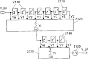
The structure of low pass filter is shown in Fig. 4. This is a common low-pass filter structure. Wherein, reference number 2110 expression delayers, reference number 2120 expression summing stages, and reference number 2130 expressions separate level. This low pass filter has the frequency limitation of one-3dB about 700KHz.
The structure of adaptively sampled device 220 is shown in Fig. 5. Wherein, maximum-value selector of reference number 2210 expressions, minimum value selector of reference number 2220 expressions. Phase inverter of reference number 2230 expressions carry out the function that multiplies each other with the factor-1, and reference number 2240 is an adder. The function of adaptively sampled device 220 is shown among Fig. 5 with open-and-shut form.
Then, image dissector 40 is carried out more detailed explanation. The basic function that dynamic contrast is improved processing procedure DCI is that frame by frame is carried out real-time analysis to image and the parameter of a binary segmentation transfer function adjusted in order to obtains the picture quality of the best according to analysis result. Will be from its three different qualities for every two field picture, i.e. on image averaging height, dark color sample distribution and the frame peak it is analyzed. The block diagram of image dissector 40 is shown in Fig. 6. Reference number 410,420,430 represents respectively mean flow rate analyzer, dark sample distribution analyzer and frame peak analyzer. The Output rusults of these devices is processed in an IIR filtering and parameter calculator 450. After the processing of this device, the parameter of binary segmentation transfer function has generated and has been sent to next frame but not present frame, in any case because filtering is always necessary, and the immediate feedback that the small time is changed is unwanted.
In television set, the form of image in use can change, as when image amplifies or receives the image such as letterbox format of different-format. When receiving the image of letterbox format, it is not the video section that all viewing areas all comprise activation. In the application scenario that image amplifies, be not to be that all video line that are activated all will be shown yet. Therefore must be careful. The part that image analysis function can be activated and not shown part are misapplied. For this reason, in analysis window parts 440, defined an analysis window. One of the definition in the scope that shows picture size of this analysis window is regional for analyzing. The analysis of DCI function is activated within this window and then is disabled outside window. By this method, also can make analytic function invalid with the mode of subhead or login. This analysis window can be by the user by inserting the mode of W_US signal, and perhaps the device W_PES by detected image form and size defines.
The below is described in detail mean flow rate analyzer 410. The central point of binary segmentation transfer function is that the value with mean picture brightness is complementary. For dark image (having the harmonic(-)mean brightness value), this point is to the low value motion, and for bright image (having high average brightness value), this point moves to the high value. Analysis is carried out as shown in Figure 7. All samplings that are lower than the dark level threshold value (=114) of depositing in the constant memory 4173 all are considered to dark sampling. The value of register 4150 is exactly the accumulation result to each sampling in this sampling. When parameter value SENS that the value of register equals to deposit in the variable store 4170, then this register is cleared, and a carry 1 is added in the average register 4160.
All samplings that are higher than the bright level threshold value (=106) of depositing in the constant memory 4172 all are considered to bright sampling, but they do not resemble and are counted simply the dark sampling. Their sampled values also will take in, in order to analyze. Therefore, for the mean flow rate analysis. The dark space sampling has different distributions from the clear zone sampling. 4140 pairs of values that provided by following formula of register add up:
Value=limit ((Y_LP-threshold value), 0,127)
As long as the value of register will be lower than constant value SENS * 32. When the value in the register 4140 during more than or equal to 32 * SENS, then this value is substituted by the value that is provided by following formula: register A=limit ((Y_LP-threshold value), 0,127)+(register-A-32 * SENS)
And from the content of average register 4160, deduct carry K according to following formula:
Register C=register C-K
The reason of using two different threshold values to make resolution between dark sampling and bright sampling is required soft transition. One be called filter area among a small circle in, threshold value 114 and 106 parallel uses. All samplings in this transition range all will be passed through by register 4150 and the dark samplings of 4140 expressions and the estimation of bright sample counter. The mean flow rate analytic function can be described by equation given below:Wherein the implication of each variable is as follows: tsn: the total number of samples P in the analysis windowSecretly: the dark number of samples Pi relevant with tsn: the bright number of samples with i value relevant with tsn,
I=limit ((sampling-threshold value), 0,127)
SENS: parameter is used for determining sensitivity
K: parameter, weighted factor
Analysis is only for the sampling in the analysis window, and carries out frame by frame. Register 4160 has comprised the information of relevant mean picture brightness when analyzing end. This result according to given scope through limiter 4120 amplitude limits, and in divider 4182 by divided by 2. Final average luminance information determines the position of transfer function central point. Before the analysis that the next frame image is carried out began, all registers carried out zero clearing by the frame quenching pulse.
Referring now to Fig. 8 the function of dark sample distribution analyzer 420 is described. Amplitude range is from 0IRE to 18IRE, and
minute 5 steps quantize, in order to dark sample distribution is analyzed. The sampling of amplitude below 18IRE is considered to dark sampling. Its quantized value is counted register 4210, as long as the value of this register is lower than the parameter value SENS in the constant memory 4270. If the value of this register is more than or equal to parameter value SENS, then the value calculated according to formula given below of its value is replaced:
And the carry that is worth for D is cut from distribution register 4220. 4230 pairs of total numbers of samples of register are counted. Its value is to add up by the value to each sampling in the analysis window to generate. If the number of samples that counts equals parameter value SENS, then this register is cleared, and carry 1 is added to register 4220.
Analysis is carried out frame by frame, and is only the sampling in the analysis window to be carried out. When analyzing end, comprised the information of relevant dark sample distribution in the register 4220 and determined that the section of the hypomere of binary segmentation transfer function gains. And here, before beginning next frame analyzed, all registers all are cleared.
Below with reference to Fig. 9 the function of frame peak analyzer 430 is described. The largest frames peak value is to be measured by the circuit that provides among Fig. 9. The each detection, maximum is stored in the register 4310. The frame peak of measuring is limited within the specific scope, in order to make the section gain of calculating in another block diagram never be lower than value 1.0 and never exceed a predetermined maximum. As below the decipher of wanting. Frame peak determines the gain of the epimere of binary segmentation transfer function. Relatively simple peak value detects, and detects as utilizing peak detector as shown in Figure 9, can produce the oversensitive problem of the section of making gain. Even the little spike of high amplitude appears in possibility in the dark image of low peak owing to catoptrical existence. Even the content of image is constant, changing also may appear in the amplitude of this little spike in time. This has just caused the modulation to the section gain. For effectively avoiding this baleful consequences. Another idea of the present invention is also taken the scale of peak value (highlights divides) into account.
What finish this task is exactly a specific embodiment of replacement frame peak analyzer 430 shown in Figure 13. Wherein, all in Fig. 9, have the parts of identical counterpart all adopt with at reference number identical shown in Fig. 9. The peak detector that plays predicting function among Figure 13 allows to insert desired peak value scale (PEAK_SIZE) take pixel number as unit. Corresponding with peak value scale value, following equation provides peak value sampling value Peak_sample:
n=min(PEAK_SIZE,11) 0≤n≤11
peak_sample=min(2
n+4,(2
15-1)) 16≤Peak_sample<2
15
The amplitude range relevant with the peak value detection that is placed into be 240 (signless 8 binary system luminance signals) from minimum peak 185 to maximum. This scope is subdivided into 16 zone of dispersions again. A comparator 4370 and a counter 4380 are set in each zone. Each counter is counted the sampling that amplitude is greater than or equal to a threshold value, and threshold value thr-00 to thr_15 transports to accordingly than device. Counter 4390 is counted during a frame image, and the value of counting is from zero to upper limit peak value Peak_sample, and this upper limit peak value is to be provided by top equation. The effect of 4380 pairs of frame peaks of each counter is to be determined by the value of counter. The value of Peak_sample is considered to 100% effect and null value is considered to 0% effect. The Peak_sample value of a counter means that 100% peak value under the effect of given threshold value detects. The count value of counter 4380 stops counting when reaching maximum Peak_sample. When analyzing end, the value of counter adds up in adder 4390 and sues for peace and normalization. This finishes by carry out simple right-shift operation in shift unit 4393 and 4395. Because required precision, the summation of obtaining is at first only moved the n position in shift unit 4393, rather than (n+4+4) position. Then, this result is multiplied by number of steps 55 (the poor 240-185=55 between peak-peak and the minimum peak draws step number) in multiplier. Final standardization in shift unit 4395, move to right 8 (binary digit) operation finish. This result is the relative peak relevant with minimum of a value 185. The relative peak of in adder 4396, calculating and minimum peak and be absolute peak. Minimum value selector 4331 and left-hand shift unit 4391,4392 are that counter 4380 is determined higher limit (Peak_sample) according to predetermined peak value scale value PEAK_SIZE.
Threshold value thr_j is provided by following equation:
For value j=0 to 15, the result of this formula shows the table following table:
|
j
|
0
|
1
|
2
|
3
|
4
|
5
|
6
|
7
|
8
|
9
|
10
|
11
|
12
|
13
|
14
|
15
|
| | | | | | | | | | | | | | | | | |
|
thr_j
|
188
|
192
|
195
|
199
|
202
|
206
|
2 09
|
213
|
216
|
219
|
223
|
226
|
230
|
233
|
237
|
240
|
Image dissector provides the signal of relevant mean flow rate, dark sample distribution and frame peak for every two field picture. The value of these information determines the performance for the transfer function of next frame image. These three values all will and be stored frame by frame through iir filter (non-quantitative pulsed filter) filtering. This wave filter represents with reference number 4520 in Figure 10, be made of multiplier 4521, shifter 4522 and 4523, adder 4524 and constant memory 4543, wherein shifter 4522 and 4523 uses respectively sampling that factor 22=4 and 24=16 will input separately. This filter time constant is to insert respectively AB_FC corresponding to average brightness value, the DS_FC corresponding with dark sample distribution value and definite with PK_FC corresponding to peak value by the user in variable store 4540,4541 and 4542. The filtering of these three image score values is to be used in the same hardware shown in Figure 10 to finish in the mode of time division multiplexing. Multiplexed control signal MUX_CTRL controls corresponding multiplexer 4510. All calculating in filtering and in params-count device 450 are all carried out in vertical blanking time.
Value through filtering is used for the parameter of binary segmentation transfer function is calculated. Remove to subtract constant 106 through the average luminance information of filtering divided by the merchant with gained after 4, the result of gained is the value of central point (TF_DPP). Dark sample distribution value through filtering is removed by 4 in shifter 4570, and the merchant of gained is the gain of the first paragraph (hypomere) of binary segmentation transfer function. For obtaining the gain of second segment (epimere), carry out additional treatments, derive from the peak value through filtering. The purpose that gain is calculated is to make the peak value that is lower than 100 IRE through filtering be converted to 100 IRE. As mentioned above, the peak value of measuring is limited in frame peak analyzer 430 in the particular range, so that the section of making gain is not less than 1.0, also is no more than predetermined maximum, such as 1.7. Maximum gain is in order to keep picture quality true to nature to define, and these conditions represent with following mathematical form:
peak=limit(peak,MINPEAK,100IRE)
1.0≤GAIN_SEG2≤max-gain2
Such as what provide in the equation below, this gain is by determining through the peak value of filtering and the position of central point.
Variable wherein represents:
GAIN_SEG2: the gain of the second segment of binary segmentation transfer function
Y100IRE: brightness signal value 100IRE
TF_DPP: the value of transfer function central point
FR_PEAK_FILT: through the brightness peak of filtering
According to this equation section gain is calculated and to make a division. This can utilize multiplier 4581 and lookup table 4550 to finish. This lookup table is comprising the result of following formula.
Its precision is n binary digit, provides in the below's table: X=FR_PEAK_FILT-TF_DPP X
min=FR_PEAK_FILT
min-TF_DPP
max
X
max=FR_PEAK_FILT
max-TF_DPP
min
ROM_Address=X-X
min
ROM_Value=2
n/ X n: the figure place behind the decimal point is worked as FR_PEAK_FILT
min=185 FR_PEAK_FILT
max=240
TF_DPP
min=32 TF_DPP
max=106
|
X=FR_PEAK_FLLT-TF_DPP
|
ROM_Address=X-X
min |
ROM_Value=2
n/ X works as n=14 |
| | | |
|
79
|
0
|
207
|
|
80
|
1
|
204
|
|
81
|
2
|
202
|
|
.
|
.
|
.
|
|
.
|
.
|
.
|
|
206
|
127
|
79
|
|
207
|
128
|
79
|
|
208
|
129
|
78
|
The transfer function section that is higher than central point of luminance signal is provided by following equation:
Yout=gain_seg2*(Y
m-TF_DPP)+TF_DPP Y
m>TF_DPP
Wherein: Yout: the output brightness signal
Yin: input luminance signal
Gain is when being divided into integer and decimal two parts face to face, and wherein the integer part perseverance is 1, below two formulas come into force:
GAIN_SEG2=GAIN_SEG2_INT+GAIN_SEG2_FRC
=1+GAIN+SEG2_FRC
Y
out=GAIN_SEG2_FRC*(Y
m-TF_DPP)+Y
m Y
m>TF_DPP
Only part can be saved one decimally. Therefore, integer part is deducted from the gain of calculating. The result is written into register 4533. The parameter TF_DPP that calculates, GAIN_SEG1_FRC and GAIN_SEG2_FRC have defined respectively transfer function extended phase plane, the fractional part of one section gain and the fractional part of two sections gains. They are all transported to binary segmentation transfer function parts. Calculate and before first data that are activated of next frame, to finish at the latest. These parameters are frozen during the data flow that is activated of this frame is passed through.
Below with reference to Figure 11 transfer function device 30 is explained in detail.
The improved video processing procedure of dynamic contrast mainly is to carry out on the basis of binary segmentation transfer function. Parameter is provided by shared iir filter and parameter calculator. The application of binary segmentation transfer function can successfully be expressed with following numeral expression formula:
When Y_CORED≤TF_DPP
Y_DSTF=(Y_CORED-TF_DPP)*GAIN_SEG1_FRC+Y_CORED
When Y_CORED>TF_DPP
Y_DSTF=(Y_CORED-TF_DPP)*GAIN_SEG2-FRC+Y_CORED
Wherein:
Y_CORED: input signal
Y_DSTF: output signal
TF_DPP: transfer function extended phase plane
GAIN_SEG1-FRC: the fractional part of one section (hypomere) gain
GAIN_SEG2-FRC: the fractional part of one section (epimere) gain
The DCI processing procedure can be inserted parameter DCI_ON by the user and start and close. At the horizontal and vertical black-out intervals, this process is closed by composite blanking signal COMP_BLANK. The hardware implement process of these calculating is shown in Figure 11 in open-and-shut mode.
Because the non-linear brightness of carrying out in transfer function is processed, color saturation changes. This consequence will be amplified to compensate by the chroma samples with compensating gain. This step is to carry out in the color saturation compensator 50 of putting on display in detail in Figure 12. The basic function of these parts represents with following formula:
Wherein:
Y_CORED: the input brightness value of binary segmentation transfer function
Y_DSTF: the output brightness value of binary segmentation transfer function
Y
b1: black
Expression formula 1/ (Y_CORED-Yb1) by lookup table 520 approximate drawing. Yield value is (Y_DSTF-Yb1)*(1/Y_CORED-Y
b1) product.
The color saturation compensation only imposes on undersaturated color. The unsaturated central point that comes across is to the second segment of 100 IRE. At the first paragraph from 0 IRE to central point, color saturation can only increase. Compensate and to make color reduction in this zone.
The content of lookup table can provide with following expression formula:
X=Y_CORED-Y
b1As Y_CORED>TF_DPPminThe time
Y_CORED
min=TF_DPP
min+1
X
min=Y_CORED
min-Y
b1
ROM_Value=2
n/X
ROM_Address=X-X
minAs X 〉=XminThe time
N is the figure place of decimal, determines approximate precision.
For X
min=17,X
max=238
|
X=Y_CORDE_Y
b1 |
ROM_Address=X-X
min |
ROM_Value=(2
n)/X works as n=13 |
| | | |
|
17
|
0
|
481
|
|
18
|
1
|
455
|
|
19
|
2
|
431
|
| | | |
| | | |
|
236
|
219
|
34
|
|
237
|
220
|
34
|
|
238
|
221
|
34
|
Color component values through overcompensation in rarely situation can surpass the maximum magnitude that represents with given figure place. Therefore, this maximum allows with component absolute calculators 561, maximum-value selector 530, limiter 512, adder 570, constant memory 553, and lookup table 521 and shifter 541 come to calculate the colour-compensating gain for each color sampling. If the color saturation compensating gain is greater than permissible value then limit it with lookup table 521, in order to avoid obvious Chroma Error occurs.
Determine that to being used for the specific embodiment that is used for replacing of color saturation compensating gain is described now. According to this alternative embodiment, the color saturation compensating gain is determined by following formula:
CSC_GAIN=Y_PWL/Y_CORED
Wherein Y_PWL uses afterwards luminance output signal of binary segmentation transfer function to luminance component, and Y_CORED is the input luminance signal component (seeing Fig. 2) of accepting the transfer function effect.
For each chroma data to U and V, the maximum color saturation compensating gain CSC_GAIN of a permissionmaxCan calculate with following formula:
CSC_GAIN
max=max_value/max(abs(U),abs(V))
Wherein, max_value is constant for a given chromatic value expression formula, for example, for 8 expression formulas of a tape symbol (make a comment or criticism, negative sign) max_value equal+127. Max (abs (U), abs (V)) represents a maximum value that chroma data is right. If the color saturation compensating gain CSC_GAIN that calculates according to following formula is greater than the maximum gain CSC_GAIN that allowsmax, then use the maximum gain CSC_GAIN that allowsmax, the Chroma Error that rises with the restriction of avoiding owing to U or V value.
Below, disturb some details of estimation device 60 to make an explanation facing to closing. The sampling threshold SNR that uses in Adaptive signal separator is determining the degree that the amplitude at treated luminance signal medium-high frequency small-signal is suppressed. It would be desirable, for low noise video equipment little sampling threshold is set, and for noisy video equipment large sampling threshold is set. The performance of system can be optimized by the mode of adjusting sampling threshold according to the noise amplitude of video equipment. And this noise is by disturbing (being noise) estimation device 60 to record.
Disturb the amplitude of the noise in the activation component of estimating 60 pairs of vision signals of device to estimate. Usually, in every width of cloth picture, exist video content and change minimum zone. These zones are applicable to noise testing. Almost be that the pixel that represents continuous (being interleaved field) of the same space position normally is closely related, and absolute difference just provide the information of noise. Owing to the deviation on the noise statistics, just be necessary to obtain the mean value of noise amplitude. Each is subdivided into 64 zones that are comprised of pixel. On each zone, the absolute difference of the pixel between the opposite field averaged. In the space and/or the zone that changes of time accurately noise amplitude can not be provided. May cause estimated noise far above in esse noise amplitude to their estimation. Therefore, noise estimation is carried out in the zone of choosing the noise amplitude minimum. This represents with the formula that provides below:
Wherein:
Xpixel: the pixel j when the front court
Xpf: the pixel j of previous field
New dynamic contrast is improved one's methods and equipment will be mainly used in video display apparatus such as direct viewing type television set or projection TV set. In plasma and LCD display device, its application can bring larger benefit.
New dynamic contrast is improved one's methods and is utilized the hardware device block diagram to carry out detailed explanation. Self-evident. Can replace the block diagram that provides with corresponding software block diagram describes.
The present invention is not limited in the specific embodiment that has provided. It is possible making various modifications, and is considered to belong within the scope of claim. For example, it is operable comparing slightly different transfer function with binary segmentation transfer function as a whole. More precisely, can revise the restriction of given position about central point. Whole dynamic contrast is improved one's methods and equipment is to be complementary with the system that processes frame by frame. And for for a system that processes, will modify.