CN1237861A - Radio communication apparatus with power consumption reduced - Google Patents
Radio communication apparatus with power consumption reduced Download PDFInfo
- Publication number
- CN1237861A CN1237861A CN99106951A CN99106951A CN1237861A CN 1237861 A CN1237861 A CN 1237861A CN 99106951 A CN99106951 A CN 99106951A CN 99106951 A CN99106951 A CN 99106951A CN 1237861 A CN1237861 A CN 1237861A
- Authority
- CN
- China
- Prior art keywords
- signal
- power supply
- section
- header
- wireless
- Prior art date
- Legal status (The legal status is an assumption and is not a legal conclusion. Google has not performed a legal analysis and makes no representation as to the accuracy of the status listed.)
- Granted
Links
Images












Classifications
-
- H—ELECTRICITY
- H04—ELECTRIC COMMUNICATION TECHNIQUE
- H04W—WIRELESS COMMUNICATION NETWORKS
- H04W52/00—Power management, e.g. Transmission Power Control [TPC] or power classes
- H04W52/02—Power saving arrangements
- H04W52/0209—Power saving arrangements in terminal devices
- H04W52/0225—Power saving arrangements in terminal devices using monitoring of external events, e.g. the presence of a signal
- H04W52/0229—Power saving arrangements in terminal devices using monitoring of external events, e.g. the presence of a signal where the received signal is a wanted signal
-
- Y—GENERAL TAGGING OF NEW TECHNOLOGICAL DEVELOPMENTS; GENERAL TAGGING OF CROSS-SECTIONAL TECHNOLOGIES SPANNING OVER SEVERAL SECTIONS OF THE IPC; TECHNICAL SUBJECTS COVERED BY FORMER USPC CROSS-REFERENCE ART COLLECTIONS [XRACs] AND DIGESTS
- Y02—TECHNOLOGIES OR APPLICATIONS FOR MITIGATION OR ADAPTATION AGAINST CLIMATE CHANGE
- Y02D—CLIMATE CHANGE MITIGATION TECHNOLOGIES IN INFORMATION AND COMMUNICATION TECHNOLOGIES [ICT], I.E. INFORMATION AND COMMUNICATION TECHNOLOGIES AIMING AT THE REDUCTION OF THEIR OWN ENERGY USE
- Y02D30/00—Reducing energy consumption in communication networks
- Y02D30/70—Reducing energy consumption in communication networks in wireless communication networks
Landscapes
- Engineering & Computer Science (AREA)
- Computer Networks & Wireless Communication (AREA)
- Signal Processing (AREA)
- Mobile Radio Communication Systems (AREA)
- Synchronisation In Digital Transmission Systems (AREA)
Abstract
无线通信装置包括接收部分(102)、电源部分(108,109)和控制部分(103)。接收部分在供电时接收无线信号,该无线信号具有存储报头图样的报头域。电源部分为接收部分供电并且响应供电停止信号停止供电。在帧同步建立状态下,控制部分在不能从接收部分接收的无线信号中检测到报头图样时产生供电停止信号。
The wireless communication device includes a receiving section (102), a power supply section (108, 109) and a control section (103). The receiving section receives a wireless signal having a header field storing a header pattern when power is supplied. The power supply section supplies power to the reception section and stops supplying power in response to a power supply stop signal. In the frame synchronization establishment state, the control section generates the power supply stop signal when the preamble pattern cannot be detected from the wireless signal received by the receiving section.
Description
发明的背景background of the invention
本发明涉及无线通信装置。更具体地,本发明涉及无线通信装置中的间歇接收控制。The present invention relates to wireless communication devices. More specifically, the present invention relates to intermittent reception control in wireless communication devices.
在无线通信装置中,通常是使消耗大量电能的无线部分的电源受控地接通和关断,从而实现间歇接收以延长电池的寿命。In a wireless communication device, it is common to turn on and off the power of the wireless part that consumes a large amount of power in a controlled manner, thereby realizing intermittent reception to prolong the life of the battery.
图3A到3C表示如无线选择呼叫接收机这样的无线通信装置接收的传输信号的格式的例子。如图3A所示,从0到14的15个周期相当于1小时。这1小时单位内的15个周期在24小时内连续发送。如图3B所示,每个周期包括从0到119共120个传输帧。如图3C所示,一个传输帧在,例如,2秒内发射。传输帧是接收的基本单元。无线通信装置可以接收所有传输帧。3A to 3C show examples of formats of transmission signals received by a radio communication device such as a radio selective calling receiver. As shown in Figure 3A, 15 cycles from 0 to 14 correspond to 1 hour. The 15 cycles in this 1-hour unit are sent continuously in 24 hours. As shown in FIG. 3B , each period includes 120 transmission frames ranging from 0 to 119. As shown in Figure 3C, a transmission frame is transmitted within, for example, 2 seconds. A transmission frame is the basic unit of reception. The wireless communication device can receive all transmission frames.
一个传输帧由32比特的报头1域、32比特的的同步信号1域、16比特的报头2域、32比特的同步信号2域、32比特的帧信息(FI)域和数据域组成。A transmission frame consists of a 32-
“1”和“0”交替出现的32比特报头(PR)信号存储在报头1域中,并且用于校正比特同步。同步信号图样1作为一个特殊的32比特图样存储在同步信号1域中,并且用于建立字同步。16比特的报头图样再次存储在下一个报头2域中。同步信号图样2存储在同步信号2域中。当前发射的传输帧号和传输帧的周期号数据存储在帧信息(FI)域中。接着,与至少一个标识符(ID)相对应的消息存储在数据域中。A 32-bit preamble (PR) signal in which "1" and "0" appear alternately is stored in the
有一种情况,即使是在使用如图3A到3C所示的传输帧的同步发射系统中,所有帧都不发射。同样,还有一种情况,使用另一种传输协议,只将传输帧的一部分用于传输。在这种情况下,由于与其它协议混合,传输有时会在几个传输帧的单位内停止,即实现了传输停顿。There is a case that all frames are not transmitted even in the synchronous transmission system using transmission frames as shown in Figs. 3A to 3C. Likewise, there is a case where, using another transport protocol, only a part of the transport frame is used for transmission. In this case, due to mixing with other protocols, the transmission sometimes stops within the unit of several transmission frames, that is, the transmission stall is realized.
图1表示在这样的同步系统中的传输停顿方式的例子。参考图1,传输停顿的周期不是恒定的,并且传输停顿后连续发射的传输帧数也不总是恒定的。当传输停顿期间积累的消息在传输开始以后全部发射完时,立刻执行下一次传输停顿。在传输停顿期间发射一个具有不同信号格式的信号。Fig. 1 shows an example of a transmission pause pattern in such a synchronous system. Referring to FIG. 1 , the period of the transmission pause is not constant, and the number of transmission frames continuously transmitted after the transmission pause is not always constant. When the messages accumulated during the transmission pause are all transmitted after the transmission starts, the next transmission pause is performed immediately. A signal with a different signal format is transmitted during a transmission pause.
在这种同步发射系统中,无线通信装置根据接收结果来确定传输帧是传输停顿帧。这样,间歇接收操作必须在假设传输停顿期间也传输同步传输帧的基础上实现。In such a synchronous transmission system, the wireless communication device determines that the transmission frame is a transmission pause frame according to the reception result. Thus, the intermittent reception operation must be implemented on the assumption that isochronous transmission frames are also transmitted during transmission pauses.
在日本专利申请公开(JP-A-Heisei 8-149542)中揭示了传输具有图3A到3C所示的同步传输信号格式的信号的无线通信装置。在这个引用的参考文献中,间歇接收控制是根据图2所示的处理流程实现的。A wireless communication device that transmits a signal having the synchronous transmission signal format shown in FIGS. 3A to 3C is disclosed in Japanese Patent Application Laid-Open (JP-A-Heisei 8-149542). In this cited reference, intermittent reception control is realized according to the processing flow shown in FIG. 2 .
现在参考图2,在开启电源之后的非同步状态(步骤ST801),开启接收部分(步骤ST802)。然后,完成检测传输帧的同步信号1或2的操作(步骤ST803)。如果检测到同步信号1和2中的任何一个,就从帧信息(FI)域中获取传输帧的传输帧号(步骤ST804)。响应于传输帧号的捕获,与传输信号建立传输帧同步(步骤ST806)。同步建立后,在预测传输帧的传输开始时向接收部分供电(步骤ST807),这样将接收部分置于ON(开启)状态(步骤ST808)。然后,如上所述完成同步信号的检测(步骤ST809)。Referring now to FIG. 2, in the asynchronous state after turning on the power (step ST801), the receiving section is turned on (step ST802). Then, the operation of detecting the
当检测到同步信号时,从随后的数据域中接收数据(步骤ST810)。当无线通信装置确定这个传输帧中的有效数据接收完成时,不等到传输帧结束就关断对接收部分的供电(步骤ST811)。When the sync signal is detected, data is received from the subsequent data field (step ST810). When the radio communication device determines that the reception of valid data in this transmission frame is completed, it turns off the power supply to the receiving part without waiting for the end of the transmission frame (step ST811).
如果未检测到同步信号,就在预测同步信号传输结束的定时停止对接收部分供电,并且关断接收部分。然后,无线通信装置等待下一个传输帧(步骤ST812)。If the synchronization signal is not detected, the power supply to the receiving section is stopped at the timing at which the transmission of the synchronization signal is predicted to end, and the receiving section is turned off. Then, the wireless communication device waits for the next transmission frame (step ST812).
在与传输帧建立同步的状态,对每一个传输帧重复从步骤ST807到步骤ST812的处理。这样,就实现了间歇接收。当预定的连续时间中未接收到传输帧时,就取消与传输帧建立的同步状态。结果,无线通信装置返回到非同步状态。In the state of establishing synchronization with the transmission frame, the processing from step ST807 to step ST812 is repeated for each transmission frame. In this way, intermittent reception is realized. When the transmission frame is not received for a predetermined continuous time, the synchronization state established with the transmission frame is canceled. As a result, the wireless communication device returns to an asynchronous state.
在图2所示的在建立与传输帧的同步状态中实现间歇接收的方法中,如果总发射传输帧就没有问题。但是,某些出现传输停顿周期的情况下,无线通信装置在实际接收无线信号之前,就不能鉴别在传输帧之间有传输停顿的情况和在传输帧之间没有传输停顿的情况。因此,接收部分必须在ON状态中对多达112比特(报头(PR)域的总比特数+同步信号1域+报头(PR)域+同步信号2域)完成检测操作。因此,从使接收部分的ON状态尽可能短的观点来说,常规无线通信装置不是很有效的。In the method of realizing intermittent reception in the state of establishing synchronization with the transmission frame shown in FIG. 2, there is no problem if the transmission frame is always transmitted. However, in some cases where a transmission pause period occurs, the wireless communication device cannot discriminate between transmission pauses between transmission frames and non-transmission frames before actually receiving wireless signals. Therefore, the receiving section must perform a detection operation on up to 112 bits (the total number of bits of the header (PR) field+
除上述常规技术以外,日本专利申请公开(JP-A-Showa 63-227134)中揭示了非同步类型的无线选择呼叫方法。这个引用文献描述了用一次拨号呼叫多个被叫方的技术。但是,它根本没有描述检测报头图样的操作。In addition to the conventional techniques described above, an asynchronous type wireless selective calling method is disclosed in Japanese Patent Application Laid-Open (JP-A-Showa 63-227134). This reference describes a technique for calling multiple called parties with one dial. However, it does not describe the operation of detecting header patterns at all.
日本专利申请公开(JP-A-Heisei 2-153633)揭示了一个可以在短时间内检测报头的非同步类型无线选择呼叫接收机。在这个引用文献中,报头检测电路在短于报头域长度对应的时间周期的特定时间内保持ON状态。在这个引用文献中,报头检测电路在与报头域同步中并不保持ON状态。另外,报头检测电路并不在整个报头域的之间内保持ON状态。如果在这个ON时间内未检测到报头,就不进行接收数据的操作。Japanese Patent Application Laid-Open (JP-A-Heisei 2-153633) discloses an asynchronous type radio selective calling receiver which can detect a header in a short time. In this cited document, the header detection circuit is kept ON for a specific time shorter than the time period corresponding to the length of the header field. In this cited document, the preamble detection circuit does not remain ON in synchronization with the preamble field. In addition, the header detection circuit does not keep the ON state between the entire header fields. If the header is not detected within this ON time, the operation of receiving data is not performed.
日本专利申请公开(JP-A-Heisei 4-304041)揭示了一个非同步类型的选择呼叫接收机。根据这个引用文献,一个1秒定时器用于检测报头。这样,必须在接收机上额外添加一个定时器,使配置变得复杂。即使报头图样尚未到达,也总要进行检测报头的操作。因此,由于接收机总处于ON状态,就要消耗电能。Japanese Patent Application Publication (JP-A-Heisei 4-304041) discloses an asynchronous type selective calling receiver. According to this citation, a 1 second timer is used to detect headers. In this way, an additional timer must be added on the receiver, making the configuration complicated. Even if the header pattern has not yet arrived, the operation of detecting the header is always performed. Therefore, since the receiver is always ON, power is consumed.
日本专利申请公开(JP-A-Heisei 8-98230)揭示了一个非同步类型的选择呼叫接收机。在这个引用文献中,当检测报头时,必须将特殊时间信息添加到传输帧中。因此,这种方法不是通用的。Japanese Patent Application Publication (JP-A-Heisei 8-98230) discloses an asynchronous type selective calling receiver. In this reference, special time information must be added to the transmission frame when checking the header. Therefore, this approach is not universal.
日本专利申请公开(JP-A-Heisei 10-23496)揭示了一个非同步类型的选择呼叫接收机。在这个引用文献中,通过在同步建立后直到接收到预定次数的同步信号之前停止接收操作,从而降低了功耗。在这个引用文献中描述了在同步建立之前通过间歇接收检测报头图样。但是,它并没有实际描述如何检测报头图样。Japanese Patent Application Publication (JP-A-Heisei 10-23496) discloses an asynchronous type selective calling receiver. In this cited document, power consumption is reduced by stopping the receiving operation after synchronization is established until a predetermined number of synchronization signals are received. In this cited document it is described to detect a preamble pattern by intermittent reception before synchronization is established. However, it doesn't actually describe how to detect header patterns.
本发明的一个目的是,提供一种可通过在同步发射系统中已经建立传输帧同步的状态下检测报头图样的出现或不出现来控制接收部分的开启时间的无线通信装置,和控制该无线通信装置的间歇接收的方法。An object of the present invention is to provide a wireless communication device capable of controlling the turn-on timing of a receiving section by detecting the presence or absence of a header pattern in a state where transmission frame synchronization has been established in a synchronous transmission system, and controlling the wireless communication A method of intermittent reception of the device.
本发明的另一个目的是,提供一种即使在使用具有传输停顿周期的传输帧的传输系统中也能够通过检测报头图样的出现或不存在来有效检测传输停顿周期的无线通信装置,和间歇接收方法。Another object of the present invention is to provide a wireless communication device capable of efficiently detecting a transmission pause period by detecting the presence or absence of a header pattern even in a transmission system using a transmission frame having a transmission pause period, and intermittent receiving method.
为了达到本发明的一个方面,无线通信装置包括接收部分、电源部分和控制部分。接收部分在电源供电时接收无线信号,而该无线信号具有存储报头图样的报头域。电源部分为接收部分供电并且响应供电停止信号终止供电。在帧同步已经建立的状态下,控制部分在不能从接收部分接收的无线信号中检测到报头图样时产生供电停止信号。In order to achieve an aspect of the present invention, a wireless communication device includes a receiving section, a power supply section and a control section. The receiving part receives a wireless signal when the power is supplied, and the wireless signal has a header field storing a header pattern. The power supply part supplies power to the reception part and terminates power supply in response to the power supply stop signal. In a state where frame synchronization has been established, the control section generates a power supply stop signal when the header pattern cannot be detected from the wireless signal received by the reception section.
控制部分在与预定参考图样一致的部分未出现在报头域中时,优选地确定报头图样未出现,以产生供电停止信号。在这种情况下,控制部分可以包括用于产生时钟信号的时钟产生电路和用于计数时钟信号的计数器,并且在计数值达到第一预定值时产生报头结束时间信号。当未在接收部分接收的无线信号中检测到与预定的参考图样一致的部分时,控制信号响应报头结束时间信号产生供电停止信号。The control section preferably determines that the header pattern is not present to generate the power supply stop signal when a portion coincident with the predetermined reference pattern does not appear in the header field. In this case, the control section may include a clock generating circuit for generating a clock signal and a counter for counting the clock signal, and generate the header end time signal when the count value reaches a first predetermined value. The control signal generates a power supply stop signal in response to the header end time signal when a portion coincident with a predetermined reference pattern is not detected in the wireless signal received by the receiving section.
另外,除报头域以外,无线信号可以拥有用于存储同步信号的同步信号域和用于存储数据的数据域。在这种情况下,控制部分可以包括用于从接收部分接收的无线信号中检测同步信号、并且在检测到报头图样出现时产生同步信号检测信号而不产生供电停止信号的同步信号检测部分,和用于响应同步信号检测信号从接收部分接收的无线信号中接收数据的数据接收部分。In addition, the wireless signal may possess a synchronization signal field for storing a synchronization signal and a data field for storing data in addition to a header field. In this case, the control section may include a synchronization signal detection section for detecting a synchronization signal from a wireless signal received by the reception section, and generating a synchronization signal detection signal without generating a power supply stop signal when presence of the preamble pattern is detected, and A data receiving section for receiving data from the wireless signal received by the receiving section in response to the synchronization signal detection signal.
另外,当控制部分检测到报头图样后的预定时间内未检测到同步信号时,控制部分向电源部分输出供电停止信号。Also, when the synchronization signal is not detected within a predetermined time after the control section detects the preamble pattern, the control section outputs a power supply stop signal to the power supply section.
计数器在计数第一预定值后计数时钟信号到第二预定值,并且当计数值达到第二预定值时产生同步信号结束时间信号。在这种情况下,当计数器计数时钟信号到达第二预定值而未检测到同步信号时,控制部分响应同步信号结束时间信号而向电源部分发送供电停止信号。The counter counts the clock signal to a second predetermined value after counting the first predetermined value, and generates a synchronous signal end time signal when the count value reaches the second predetermined value. In this case, when the count clock signal of the counter reaches the second predetermined value without detecting the synchronization signal, the control section sends a power supply stop signal to the power supply section in response to the synchronization signal end time signal.
为了获得本发明的另一方面,无线通信装置包括接收部分、电源部分和控制部分。当在帧同步建立的状态下供电时,接收部分接收无线信号,该无线信号具有存储报头图样的报头域。电源部分响应供电开始信号为接收部分供电,并且响应供电停止信号终止为接收部分供电。控制部分在报头域开始定时时产生供电开始信号,并且在无法从接收部分接收的无线信号中检测到报头图样时产生供电停止信号。In order to obtain another aspect of the present invention, a wireless communication device includes a receiving section, a power supply section, and a control section. When power is supplied in a state in which frame synchronization is established, the receiving section receives a wireless signal having a header field storing a header pattern. The power supply part supplies power to the reception part in response to the power supply start signal, and terminates power supply to the reception part in response to the power supply stop signal. The control section generates a power supply start signal at the start timing of the header field, and generates a power supply stop signal when the header pattern cannot be detected from the wireless signal received by the reception section.
为了获得本发明的另一方面,无线通信装置包括接收部分、电源部分和控制部分。当在帧同步建立的状态下供电时,接收部分接收无线信号,该无线信号具有存储报头图样的报头域。电源部分响应供电开始信号为接收部分供电,并且响应供电停止信号终止为接收部分供电。控制部分在报头域开始定时以前一个预定的时间产生供电开始信号,并且在无法从接收部分接收的无线信号中检测到报头图样时产生供电停止信号。In order to obtain another aspect of the present invention, a wireless communication device includes a receiving section, a power supply section, and a control section. When power is supplied in a state in which frame synchronization is established, the receiving section receives a wireless signal having a header field storing a header pattern. The power supply part supplies power to the reception part in response to the power supply start signal, and terminates power supply to the reception part in response to the power supply stop signal. The control section generates a power supply start signal a predetermined time before the header field start timing, and generates a power supply stop signal when the header pattern cannot be detected from the wireless signal received by the reception section.
为了获得本发明的另一方面,一种在无线通信装置处于同步建立状态时的间歇接收的方法包括:In order to obtain another aspect of the present invention, a method for intermittent reception when a wireless communication device is in a synchronization establishment state includes:
当为接收部分供电时,接收部分接收无线信号,该无线信号具有存储报头图样的报头域;When power is supplied to the receiving part, the receiving part receives a wireless signal having a header field storing a header pattern;
为接收部分供电;Power the receiving part;
响应供电停止信号,终止为接收部分供电;和terminating power to the receiving portion in response to the power stop signal; and
当无法从接收部分接收的无线信号中检测到报头图样时产生供电停止信号。The power supply stop signal is generated when the header pattern cannot be detected from the wireless signal received by the receiving section.
图1描述传输停顿帧;Figure 1 describes the transmission pause frame;
图2是描述常规无线通信装置的操作的流程图;2 is a flowchart describing the operation of a conventional wireless communication device;
图3A到3C描述无线通信装置中使用的同步传输信号;3A to 3C describe synchronous transmission signals used in wireless communication devices;
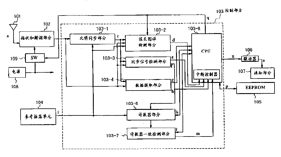
图4是表示根据本发明第一实施例的无线通信装置的结构的框图;4 is a block diagram showing the configuration of a wireless communication device according to a first embodiment of the present invention;
图5是表示根据本发明第一实施例的无线通信装置中报头图样检测部分的结构的框图;5 is a block diagram showing the structure of a header pattern detection section in the wireless communication device according to the first embodiment of the present invention;
图6A到6M是解释根据本发明第一实施例的无线通信装置中报头图样检测部分的操作的定时图;6A to 6M are timing charts for explaining the operation of the header pattern detecting section in the wireless communication device according to the first embodiment of the present invention;
图7是描述根据本发明第一实施例的无线通信装置的操作的流程图;7 is a flowchart describing the operation of the wireless communication device according to the first embodiment of the present invention;
图8A到8F是解释根据本发明第一实施例的无线通信装置和常规无线通信装置之间的间歇接收控制方法的区别的定时图;8A to 8F are timing charts explaining the difference of the intermittent reception control method between the wireless communication device according to the first embodiment of the present invention and the conventional wireless communication device;
图9是表示根据本发明第二实施例的无线通信装置的结构的框图;9 is a block diagram showing the configuration of a wireless communication device according to a second embodiment of the present invention;
图10是描述根据本发明第二实施例的无线通信装置的操作的流程图;10 is a flowchart describing the operation of the wireless communication device according to the second embodiment of the present invention;
图11是描述根据本发明第三实施例的无线通信装置的操作的流程图;11 is a flowchart describing the operation of the wireless communication device according to the third embodiment of the present invention;
图12A到12F是解释根据本发明第三实施例的无线通信装置和常规无线通信装置之间的间歇接收控制方法的区别的定时图;12A to 12F are timing charts explaining differences in intermittent reception control methods between a wireless communication device according to a third embodiment of the present invention and a conventional wireless communication device;
图13是表示根据本发明第三实施例的无线选择呼叫接收机中的报头图样检测部分改进例子的结构的框图。Fig. 13 is a block diagram showing a structure of a modified example of a preamble pattern detection section in a radio selective calling receiver according to a third embodiment of the present invention.
下面将参考附图描述本发明的无线通信装置。在下面的描述中,将以无线选择呼叫接收机为例描述无线通信装置的间歇接收控制。The wireless communication device of the present invention will be described below with reference to the drawings. In the following description, the intermittent reception control of the wireless communication device will be described taking a wireless selective calling receiver as an example.
图4是表示根据本发明第一实施例的无线通信装置的结构的框图。参考图4,根据第一实施例的无线通信装置由天线101、接收和解调部分102、控制部分103、参考振荡单元104,EEPROM 105、驱动器106、通知部分107和电源部分组成。电源部分包括电源108和开关(SW)109。FIG. 4 is a block diagram showing the configuration of a wireless communication device according to the first embodiment of the present invention. Referring to Fig. 4, the wireless communication device according to the first embodiment is made up of antenna 101, receiving and
当从电源108向接收和解调部分供电时,接收和解调部分102放大并解调天线101接收的无线信号a,并随后输出解调信号b。这个无线信号a具有图3A到3C所示的帧结构。When the receiving and demodulating section is supplied with power from the
参考振荡单元104振荡并产生参考振荡时钟信号i。The
事先在可以被电擦除并重写的可编程只读存储器(此后称为EEPROM)105中设置一个内部站(intra-station)ID。An intra-station ID is set in advance in a programmable read-only memory (hereinafter referred to as EEPROM) 105 which can be electrically erased and rewritten.
控制部分103从解调信号b中提取传输数据中包含的消息和ID,并且将EEPROM 105中存储的ID和所发射的ID相比较。随后,如果确定两个ID相符合,并且进一步存在一个发向外部站(inter-station)的消息,控制部分103就输出驱动信号n。The control section 103 extracts the message and ID contained in the transmission data from the demodulated signal b, and compares the ID stored in the
通知部分107由振铃单元、振荡单元、LED或LCD(液晶显示器)等组成。控制部分103用驱动信号n驱动驱动器106。驱动器106通过信号线o驱动通知部分107以便通知接收机的用户接收到消息。The
电源108为整个装置供电。开关109响应供电开始信号q为接收和解调部分102供电。另外,开关109响应供电停止信号q停止为接收和解调部分102供电。A
控制部分103由比特同步部分103-1、报头(PR)图样检测部分103-2、同步信号检测部分103-3、数据提取部分103-4、计数器部分103-6、计数器一致检测部分103-7和具有中断控制器的CPU 103-8组成。The control section 103 is composed of a bit synchronization section 103-1, a header (PR) pattern detection section 103-2, a synchronization signal detection section 103-3, a data extraction section 103-4, a counter section 103-6, and a counter coincidence detection section 103-7. and a CPU 103-8 with an interrupt controller.
比特同步部分103-1从解调信号b和来自参考振荡单元104的参考振荡时钟信号I中为数据抽样产生重建时钟信号c。The bit synchronization section 103-1 generates a reconstruction clock signal c for data sampling from the demodulation signal b and the reference oscillation clock signal I from the
报头图样检测部分103-2从重建时钟信号c、解调信号b和参考振荡时钟信号i中检测报头图样是否出现在解调信号b的报头1域或报头2域中。如果检测到报头图样,就将检测信号d设置为高电平。如果未检测到报头图样,就将检测信号d设置为低电平。报头信号的出现或不存在是通过比较预定比特数的参考图样和报头域中解调信号的数据而检测的。是根据这样的方法确定比特数的,即,一个数据传输帧将不会被错误地识别为传输停顿帧。这样,希望能从普通传输帧中很容易地区分传输停顿中的传输停顿帧比特数。在这个实施例中,参考图样包括5个比特。The preamble pattern detecting section 103-2 detects whether a preamble pattern appears in the
同步信号检测部分103-3使用重建的时钟信号c从解调信号b的同步信号1域或同步信号2域中检测同步信号。如果检测到同步信号,同步信号检测部分103-3将同步信号检测信号f作为中断信号e输出到CPU103-8的中断控制器。另外,检测部分103-3向计数器103-6输出帧同步信号f。The sync signal detecting section 103-3 detects a sync signal from the
数据提取部分103-4有一个缓冲器(未示出),使用重建时钟信号c从解调信号b的包括ID的数据域中提取传输数据,并且将它存储在缓冲器中。将数据存储在缓冲器中以后,数据提取部分103-4将数据存储结束信号h作为中断信号输出到CPU103-8的中断控制器。另外,数据提取部分103-4读出缓冲器中存储的数据,并作为数据信号g输出给CPU103-8,然后从CPU103-8接收数据信号g,并存储在缓冲器中。The data extracting section 103-4 has a buffer (not shown), extracts transmission data from the data field including ID of the demodulated signal b using the reconstructed clock signal c, and stores it in the buffer. After storing the data in the buffer, the data extraction section 103-4 outputs a data storage end signal h as an interrupt signal to the interrupt controller of the CPU 103-8. Also, the data extraction section 103-4 reads out the data stored in the buffer and outputs it to the CPU 103-8 as a data signal g, and then receives the data signal g from the CPU 103-8 and stores it in the buffer.
计数器部分103-6有分频器、比特计数器、传输帧计数器和周期计数器(未示出),并与同步检测信号f同步地计数时钟信号i。The counter section 103-6 has a frequency divider, a bit counter, a transmission frame counter, and a cycle counter (not shown), and counts the clock signal i in synchronization with the synchronization detection signal f.
分频器将时钟信号i进行分频。比特计数器计数参考振荡时钟信号i,并且指示传输帧中的当前比特位置。因此,一旦建立同步状态,传输帧中每个报头域、同步信号域、FI域和数据域的开始定时都可以通过计数分频的时钟信号来检测,直到取消同步状态。换句话说,比特计数器维持与相应传输帧的同步。因此,比特计数器用于维持与传输帧同步。比特计数器响应帧同步信号f而复位为预定值。帧计数器通过计数比特计数器的输出从而来计数接收的帧数。周期计数器通过计数传输帧计数器的输出从而来计数接收的周期数。The frequency divider divides the frequency of the clock signal i. The bit counter counts the reference oscillating clock signal i and indicates the current bit position in the transmission frame. Therefore, once the synchronization state is established, the start timing of each header field, synchronization signal field, FI field and data field in the transmission frame can be detected by counting the frequency-divided clock signal until the synchronization state is canceled. In other words, the bit counter maintains synchronization with the corresponding transmission frame. Therefore, a bit counter is used to maintain synchronization with the transmission frame. The bit counter is reset to a predetermined value in response to the frame synchronization signal f. The frame counter counts the number of frames received by counting the output of the bit counter. The cycle counter counts the number of cycles received by counting the output of the transmit frame counter.
计数器一致检测部分103-7不断比较CPU103-8设置的值1和计数器部分103-6的计数器值。如果检测到设置值1和计数器值一致,计数器一致检测部分103-7就向CPU103-8的中断控制器输出一致信号m.。The counter coincidence detection section 103-7 constantly compares the
CPU103-8可以通过信号线k设置计数器部分103-6中的计数器值。另外,CPU103-8可以将当前计数器值读出作为值1。即,CPU103-8相应于报头1域、同步信号1域、报头2域和同步信号2域的时间长度设置计数器一致检测部分103-7中的值1。此外,CPU103-8从数据提取部分103-4中存储的传输帧FI域中读出传输帧信息。传输帧信息包括传输帧号和周期号的信息。当读出传输帧信息时,CPU103-8分别设置计数器部分103-6的帧计数器和周期计数器的传输帧值和周期值。The CPU 103-8 can set the counter value in the counter section 103-6 through the signal line k. In addition, the CPU 103-8 can read the current counter value as
在与传输帧建立同步的状态下,CPU103-8在报头域开始的定时时刻向开关109输出供电开始信号q。同时,CPU103-8根据通过信号线d来自报头图样检测部分103-2的报头图样检测信号,可以得知是否检测到报头图样。响应来自报头图样检测部分103-2的检测信号d,CPU103-8向开关109选择输出供电停止信号q。即,如果检测信号d在相应于报头1域或报头2域的计数器一致检测信号m输入时保持低电平,则CPU103-8就向开关109输出供电停止信号q。In a state in which synchronization with the transmission frame is established, the CPU 103 - 8 outputs a power supply start signal q to the
根据来自同步信号检测部分103-3的同步信号检测信号e,CPU103-8知道是否检测到同步信号。响应来自同步信号检测部分103-3的同步信号检测信号e,CPU103-8向开关109选择地输出供电停止信号q。即,如果虽然有相应于报头1域或报头2域的计数器一致检测信号m被输入,但却并未输入同步信号检测信号e,则CPU103-8就向开关109输出供电停止信号q。Based on the sync signal detection signal e from the sync signal detecting section 103-3, the CPU 103-8 knows whether or not the sync signal is detected. In response to the sync signal detection signal e from the sync signal detection section 103-3, the CPU 103-8 selectively outputs the power supply stop signal q to the
这样,就控制了电源对接收和解调部分102的供电定时。In this way, the timing of supplying power to the receiving and
此外,CPU103-8响应从数据提取部分103-4到中断控制器的数据存储结束信号h,通过数据信号g从数据提取部分103-4的缓冲器中读出接收数据。如果根据接收的数据和事先存储在EEPROM 105中的内部站ID而确定出现的消息是发送到内部站的,CPU103-8就向驱动器106输出信号n,通知接收机的用户接收到消息。Further, the CPU 103-8 reads out received data from the buffer of the data extraction section 103-4 through the data signal g in response to the data storage end signal h from the data extraction section 103-4 to the interrupt controller. If it is determined based on the received data and the internal station ID stored in the
图5是报头图样检测部分103-2的详细框图。图5中,信号线b,i,c,q和d分别对应于图4中的信号或信号线。FIG. 5 is a detailed block diagram of the header pattern detection section 103-2. In FIG. 5, signal lines b, i, c, q and d correspond to the signals or signal lines in FIG. 4, respectively.
参考图5,报头图样检测部分103-2由移位时钟产生电路201、选择器202、移位寄存器203、比较器204、判决电路205和保持电路206组成。Referring to FIG. 5 , the header pattern detection section 103 - 2 is composed of a shift
分别如图6C,6D,6E,6F和6G所示,时钟产生电路201从重建时钟信号c和参考振荡时钟信号i中产生定时信号A,B,C,D和I。这里,如图6B所示,假设当重建时钟信号c被分为28个部分时,参考振荡时钟信号i是一个周期。As shown in FIGS. 6C, 6D, 6E, 6F and 6G respectively, the
如图6C所示,信号A是当数据比特被分为28个部分时,在数据比特的第二半的开始(即,在第15时钟信号)处产生的一个具有半时钟信号长度的脉冲信号。如图6D所示,信号B是一个在第21时钟信号处上升、在第26时钟信号处下降的信号。如图6E所示,信号C是信号线B和参考振荡时钟信号i相与得到的信号。如图6F所示,信号D是周期等于信号C的两倍的时钟信号。信号D是将信号C分频以使其从信号C的上升沿开始具有比特图样“10101”所获得的信号。比特图样用于比较参考图样。在这个实施例中,使用5比特“10101”的参考图样。如图6G所示,信号I是在第27时钟信号处产生的具有半个时钟信号长度的脉冲。As shown in FIG. 6C, signal A is a pulse signal with a half clock signal length generated at the beginning of the second half of the data bit (i.e., at the 15th clock signal) when the data bit is divided into 28 parts . As shown in FIG. 6D, signal B is a signal that rises at the 21st clock signal and falls at the 26th clock signal. As shown in FIG. 6E , the signal C is a signal obtained by ANDing the signal line B and the reference oscillation clock signal i. Signal D is a clock signal with a period equal to twice that of signal C, as shown in FIG. 6F. The signal D is a signal obtained by dividing the frequency of the signal C so that it has a bit pattern "10101" from the rising edge of the signal C. Bit patterns are used for comparison with reference patterns. In this embodiment, a reference pattern of 5 bits "10101" is used. As shown in FIG. 6G, signal I is a pulse having a length of half a clock signal generated at the 27th clock signal.
另外,图6H,6I和6J表示当参考图样出现在报头图样中时,信号b,H和d的波形。图6K,6L和6M表示当参考图样未出现在报头图样中时,信号b,H和d的波形。In addition, FIGS. 6H, 6I and 6J show waveforms of signals b, H and d when the reference pattern appears in the header pattern. 6K, 6L and 6M show the waveforms of signals b, H and d when the reference pattern does not appear in the header pattern.
参考图5,选择器202根据作为选择控制信号的信号B,选择并输出信号E和解调信号b中的任意一个。如果信号B处于高电平,选择器202选择信号E,而如果信号B处于低电平,则选择解调信号b。如图6D所示,信号最初处于低电平。因此,解调信号b中的1比特、特别是报头图样是响应图6C中所示的信号A选择的。此后,如果信号B被设置为高电平,则选择来自移位寄存器203的输出。Referring to FIG. 5, the
移位寄存器203是具有N-比特结构的移位寄存器,并且移位寄存器203中的移位和数据输出是以比特为单位的,与从或门207输入到移位寄存器203的CLK端的信号的上升沿同步。在这个实施例中,N=5。同时,输入选择器202选中的比特。当同一周期中重建时钟信号c处于低电平时,到移位寄存器203的输入就被信号B切换到输出E端。然后,移位寄存器203的5比特数据响应信号C的脉冲而循环。即,如图6K所示,响应信号A,将选择器202选中的报头图样的比特写入移位寄存器203。因此,如果报头图样的每一比特都发送了,报头图样的最新5比特保持在移位寄存器203中。此后,响应图6E中所示的信号C,从移位寄存器输出保持的比特。The
比较器204由倒相器204-1和异或门204-2,204-3组成。如图6F所示,参考图样D的每一比特都从移位时钟产生电路201发送到比较器204。比较器204的倒相器204-1将参考图样比特倒置。参考图样比特和倒置的图样比特被发送到异或门204-2和024-3。同时,报头图样的最新5比特从移位寄存器203发送到异或门204-2和204-3。这样,以比特为单位,通过异或门204-2和204-3,分别将参考图样比特和倒置的参考图样比特与移位寄存器的输出E比较。从异或门204-2和204-3分别将以比特为单位的比较结果作为信号F和G输出到判决电路205。如果比较结果指示彼此一致,信号F和G就处于高电平。如果信号F保持高电平,判决电路205就可以检测报头图样的出现。The
当处于复位电平(即处于高电平)的信号A被发送到判决电路205的RST端时,输出H被初始化为“1”。判决电路在时钟信号C的下降沿确定一致检测信号F和G的电平。如图6K,6L和6M所示,当信号F和G处于低电平,指示在5比特比较中检测到不一致时,将低电平作为输出H来输出。另一方面,如图6H,6I和6J所示,如果信号F或G处于高电平,指示在5比特比较中检测到一致时,将高电平作为输出H来输出。输出H被保持电路206与信号I的脉冲定时同步而锁存。锁存在高电平的信号I一直保持到电源响应于供电停止信号q停止对接收和解调部分203供电为止。这样,就确定了报头图样的出现或不存在。When the signal A at the reset level (ie at the high level) is sent to the RST terminal of the
如图6A到6M所示,当在报头图样的一部分和“10101”参考图样之间检测到一致时,在它们被相互比较的同时,信号H保持在高电平。因此,信号H被信号I锁存,而输出d也输出在高电平。如果从第4比特的比较结果确定它们是不一致的,信号H就切换到低电平,并且输出d也设置为指示不一致的低电平。As shown in FIGS. 6A to 6M, when a coincidence is detected between a part of the header pattern and the "10101" reference pattern, the signal H is kept at a high level while they are compared with each other. Therefore, the signal H is latched by the signal I, and the output d is also output at a high level. If they are determined to be inconsistent from the comparison result of the 4th bit, the signal H is switched to a low level, and the output d is also set to a low level indicating the inconsistency.
下面将参考图7中的处理流程描述根据本发明的无线通信装置的间歇接收。与参考图2描述的常规例子类似,假设已经建立了与传输帧的同步。The intermittent reception of the wireless communication device according to the present invention will be described below with reference to the processing flow in FIG. 7 . Similar to the conventional example described with reference to FIG. 2, it is assumed that synchronization with a transmission frame has already been established.
目前因为开关109断开,所以并未给接收和解调部分102供电。另外,CPU103-8在计数器一致检测部分103-7中设置了指示报头域开始的定时数据。因为与传输帧的同步已经建立,计数器一致检测部分103-7根据计数器部分103-6的输出,确定该定时是否与报头传输定时一致(步骤ST401)。如果定时彼此不一致,就重复步骤ST401的操作直到定时彼此一致。Currently, the receiving and
如果CPU103-8根据计数器一致检测部分103-7的计数器一致检测信号m确定报头传输,CPU103-8就向开关109输出供电开始信号。响应供电开始信号,开关109从电源108向接收和解调部分102传送电能。结果,接收和解调部分102可以启动(步骤ST402)。If the CPU 103-8 determines header transmission based on the counter coincidence detection signal m of the counter coincidence detection section 103-7, the CPU 103-8 outputs a power supply start signal to the
接着,CPU103-8为计数器部分103-6设置指示报头1域结束的定时数据。计数器一致检测部分103-7根据计数器部分103-6的输出,确定当前的定时是否与报头结束定时一致(步骤ST403)。如果两个定时彼此不一致,就重复步骤ST403的操作,直到一致为止。Next, the CPU 103-8 sets timing data indicating the end of the
在报头传输结束定时过后,CPU103-8根据来自报头图样检测部分103-2的报头图样检测信号d确定是否检测到报头图样(步骤ST404)。如果未检测到报头图样,CPU103-8就向开关109输出供电停止信号q。响应供电停止信号,开关109停止从电源108向接收和解调部分102供电。因此,接收和解调部分102关断(步骤ST409)。After the header transmission end timing has elapsed, the CPU 103-8 determines whether a header pattern is detected based on the header pattern detection signal d from the header pattern detection section 103-2 (step ST404). If no header pattern is detected, the CPU 103-8 outputs a power supply stop signal q to the
此后,CPU103-8为计数器部分103-6设置与下一个传输帧的报头传输定时相应的数据。举例而言,如果未检测到报头1域的报头图样,CPU103-8在计数器部分103-6中设置与报头2域的头部定时相对应的数据。另外,如果未检测到报头2域的报头图样,CPU103-8就在计数器部分103-6中设置与下一帧的报头1域的头部定时相对应的数据。Thereafter, the CPU 103-8 sets data corresponding to the header transmission timing of the next transmission frame to the counter section 103-6. For example, if the header pattern of the
如果根据报头图样检测信号d,确定检测到报头图样,CPU103-8就不输出供电停止信号q。这样,接收和解调部分102保持在0N状态。然后,同步信号检测部分103-3执行检测同步信号1或2的过程(步骤ST405)。If it is determined from the header pattern detection signal d that the header pattern is detected, the CPU 103-8 does not output the power supply stop signal q. Thus, the reception and
当检测到同步信号1或2时,同步信号检测部分103-3将同步信号检测信号e作为中断信号输出到CPU103-8。当根据同步信号检测信号e确定已经检测到同步信号,并且进一步根据计数器一致检测信号m确定已经经过了预定时间,CPU103-8就从数据提取部分103-4中的缓冲器读出传输帧的ID(步骤ST408)。传输帧的ID与从EEPROM105中读出的ID进行比较。When the
如果确定ID彼此一致,并且进一步接收到发送到外部站的有效数据,CPU103-8不等到传输帧的传输结束就向开关109输出供电停止信号q。响应供电停止信号q,开关109停止通过电源108向接收和解调部分102供电。结果,接收和解调部分102被关断(步骤S409)。此后,CPU103-8在计数器部分103-6中设置与下一个传输帧的报头传输定时相应的数据。If it is determined that the IDs coincide with each other, and further valid data transmitted to the external station is received, the CPU 103-8 outputs a power supply stop signal q to the
如果在步骤ST406,通过同步信号检测信号h确定未检测到同步信号,则CPU103-8确定是否已经超过了同步信号结束定时(步骤ST407)。如果未超过同步信号结束定时,就重复步骤ST406的操作。如果通过计数器一致检测信号m确定已经超过了同步信号结束定时,CPU103-8就向开关109输出供电停止信号q。响应供电停止信号q,开关109停止从电源108向接收和解调部分102供电。结果,接收和解调部分102被关断(步骤ST409)。此后,CPU103-8为计数器103-6设置与下一个传输帧的报头传输定时相应的数据。If in step ST406, it is determined by the sync signal detection signal h that no sync signal has been detected, the CPU 103-8 determines whether or not the sync signal end timing has passed (step ST407). If the synchronization signal end timing has not passed, the operation of step ST406 is repeated. The CPU 103 - 8 outputs a power supply stop signal q to the
图8A到8F表示根据本发明同步建立期间间歇接收控制的波形。图8A表示发射传输帧的状态。这给出了只发射传输帧0,1,和2以及传输帧15,16而停止发射其它传输帧的情况。图8B是表示在第一实施例中向接收和解调部分102供电的ON波形。图8C是表示在常规无线通信装置中向接收和解调部分102供电的ON波形。如果发射传输帧,这两个波形就是完全一致的。但是,在出现传输停顿帧的部分,在本发明中只有报头部分具有ON波形。应该理解,与常规通信装置中一直向接收和解调部分供电到同步信号2的结束部分的ON波形相比,缩短了供电时间。8A to 8F show waveforms of intermittent reception control during synchronization establishment according to the present invention. Fig. 8A shows the state of transmitting a transmission frame. This gives the situation where
下面将以无线选择呼叫接收机为例描述根据本发明第二实施例的无线通信装置。图9是解释根据本发明第二实施例作为无线通信装置的无线选择呼叫接收机的结构的框图。A wireless communication apparatus according to a second embodiment of the present invention will be described below taking a wireless selective calling receiver as an example. FIG. 9 is a block diagram explaining the structure of a wireless selective calling receiver as a wireless communication device according to a second embodiment of the present invention.
从图9中可以理解,第二实施例中的无线选择呼叫接收机的结构与第一实施例很类似。它们之间的区别在于报头图样检测部分103-2的报头图样检测信号d被作为中断信号而传送到CPU103-8的中断控制器。As can be understood from FIG. 9, the structure of the radio selective calling receiver in the second embodiment is very similar to that of the first embodiment. The difference between them is that the preamble pattern detection signal d of the preamble pattern detection section 103-2 is transmitted as an interrupt signal to the interrupt controller of the CPU 103-8.
下面将参考图10描述第二实施例中无线选择呼叫接收机的操作。The operation of the wireless selective calling receiver in the second embodiment will be described below with reference to FIG. 10. FIG.
参考图10,步骤STS01,ST502与图7中的步骤ST401,ST402类似。步骤ST503的操作类似于图7中步骤ST404的操作。Referring to FIG. 10 , steps STS01 and ST502 are similar to steps ST401 and ST402 in FIG. 7 . The operation of step ST503 is similar to the operation of step ST404 in FIG. 7 .
在第二实施例中,如果未检测到报头图样,就执行步骤ST504的操作。步骤ST504的操作与步骤ST403类似。作为步骤ST504执行的结果,如果当前时间不是报头域的传输结束定时,控制返回步骤ST503。即,在开关109打开、从电源108向接收和解调部分102供电(步骤ST502)之后,该控制将等待报头图样检测中断信号d(步骤ST503),直到报头传输结束定时的结束。In the second embodiment, if no header pattern is detected, the operation of step ST504 is performed. The operation of step ST504 is similar to that of step ST403. As a result of execution of step ST504, if the current time is not the transmission end timing of the header field, control returns to step ST503. That is, after the
如果在步骤ST503报头图样检测部分103-2检测到报头图样,就将报头图样检测信号d作为中断信号发送到CPU103-8。If the preamble pattern detection section 103-2 detects a preamble pattern at step ST503, it sends a preamble pattern detection signal d as an interrupt signal to the CPU 103-8.
接着执行步骤ST505的操作。步骤ST505的操作与步骤ST405类似。即,如果产生了报头图样检测中断信号d,就不产生供电停止信号q。从电源108向接收和解调部分102供电。接收和解调部分102保持在ON状态。此后,控制进行到检测同步信号的操作(步骤ST505)。在下文中,步骤ST506,ST507,ST508和ST509的操作与步骤ST406,ST407,ST408和ST409类似。Next, the operation of step ST505 is performed. The operation of step ST505 is similar to that of step ST405. That is, if the preamble pattern detection interruption signal d is generated, the power supply stop signal q is not generated. The reception and
另外,如果在步骤ST504是报头域的结束定时,就继续执行步骤ST509的操作。即,如果超过报头传输结束定时而未产生检测中断信号d,就向开关109输出停止供电信号q,从而关断开关109(步骤ST509)。Also, if it is the end timing of the header field in step ST504, the operation of step ST509 is continued. That is, if the detection interrupt signal d is not generated after the header transfer end timing has elapsed, the power supply stop signal q is output to the
下面将以无线选择呼叫接收机为例描述本发明第三实施例的无线通信装置。图11是表示根据本发明第三实施例的无线选择呼叫接收机的框图。A wireless communication apparatus according to a third embodiment of the present invention will be described below taking a wireless selective calling receiver as an example. Fig. 11 is a block diagram showing a radio selective calling receiver according to a third embodiment of the present invention.
通过图11可以理解,第三实施例中的无线选择呼叫接收机与第一实施例中的类似。它们之间的区别在于从计数器部分103-6向报头图样检测部分103-2发送信号s。As can be understood from FIG. 11, the wireless selective calling receiver in the third embodiment is similar to that in the first embodiment. The difference between them is that the signal s is sent from the counter section 103-6 to the preamble pattern detection section 103-2.
下面将参考图12A到12F描述第三实施例中的无线选择呼叫接收机的操作。参考图12A到12F,图12A到12F(除图12E以外)与图8A到8D和8F类似。The operation of the radio selective calling receiver in the third embodiment will be described below with reference to Figs. 12A to 12F. Referring to FIGS. 12A to 12F , FIGS. 12A to 12F (except FIG. 12E ) are similar to FIGS. 8A to 8D and 8F.
在第三实施例中,CPU103-8为计数器一致检测部分103-7设置一个与比报头域提前时间T的定时相应的数据。如果从计数器一致检测部分103-7输出计数器一致检测信号m,CPU103-8就向开关109输出供电开始信号q。结果,接收和解调部分102被开启。此后,计数器部分103-6在报头域的开始定时产生输出到报头图样检测部分103-2的信号s。响应信号s,报头图样检测部分103-2启动与第一实施例类似的操作。这是因为:即,即使供电,接收和解调部分102也不能立即进入稳定工作状态。出于这个原因,提前时间T供电,就可以在接收和解调部分102进入稳定工作状态以后接收报头图样。In the third embodiment, the CPU 103-8 sets a data corresponding to a timing earlier than the header field by the time T to the counter coincidence detection section 103-7. When a counter coincidence detection signal m is output from the counter coincidence detection section 103-7, the CPU 103-8 outputs a power supply start signal q to the
此外,由于已经供电,即使接收和解调部分是不稳定的,也可能担心会将以前帧的数据部分错误地检测为报头图样。因此,响应信号s而开始报头图样检测部分的操作。Also, since the power is already supplied, even if the receiving and demodulating sections are unstable, there may be fears that the data section of the previous frame will be erroneously detected as a header pattern. Therefore, the operation of the header pattern detection section is started in response to the signal s.
其它操作与图7中所示的类似。因此就不再解释。Other operations are similar to those shown in FIG. 7 . Therefore no further explanation.
下面将参考图13描述本发明第三实施例的改进例子中的报头图样检测部分。A header pattern detection section in a modified example of the third embodiment of the present invention will be described below with reference to FIG. 13 .
参考图13,移位时钟产生电路201、选择器202、移位寄存器203、比较器204、判决电路205和保持电路206分别与图5中所示的类似。此外,这个实施例中添加了触发器208和与门209和210。计数器部分103-6每次更新帧时都产生信号s。响应信号s,触发器208设置为高电平电压Vdd。结果,可以从Q输出端输出高电平的信号。这个高电平信号发送到与门209和210。图5中的信号C和I发送到与门209和210。结果,当信号s输入时,即,当帧更新时,可以输出图5中的信号C和I。响应信号Q,触发器与保持电路206同时被复位。结果,从触发器208的Q输出端输出低电平信号。Referring to FIG. 13 , shift
如上面提到的,在根据本发明的无线通信装置的间歇接收方法中,报头图样检测部分103-2使用来自接收和解调部分102的解调信号b、由比特同步部分105-1输出的重建时钟C和参考时钟信号。因此,可以检测报头图样的出现或不存在。举例而言,如果假设参考图样中的比特数是5,就可以在报头图样中检测是否缺少图样“10101”或倒置的图样“01010”。检测的结果作为报头图样检测信号d输出。信号d的高电平指示检测到图样,而信号d的低电平指示未检测到图样。As mentioned above, in the intermittent receiving method of the wireless communication apparatus according to the present invention, the preamble pattern detecting section 103-2 uses the demodulated signal b from the receiving and
接收和解调部分102在报头域的传输定时开启。接收和解调部分102保持0N状态,直到报头域的传输结束定时为止。根据信号d,确定是否在传输结束定时之前检测到报头图样。如果未检测到报头图样,开关109关断,同时接收和解调部分102也关断。此后,接收和解调部分102保持在等待状态,直到下一个传输帧的报头域的传输定时为止。The reception and
如果检测到报头图样,开关109保持在ON状态。结果,接收和解调部分可以保持在ON状态。接着,执行检测同步信号的操作。如果直到同步信号的传输结束定时都未检测到同步信号,则开关109关断,同时接收和解调部分也关断。此后,等待下一个传输帧。If the header pattern is detected, the
如果检测到同步信号,就成功地完成了数据接收。当确定对这个传输帧中的有效数据的接收已经结束时,不等到传输帧的结束,开关109就关断,同时接收和解调部分也关断。If the sync signal is detected, data reception is successfully completed. When it is determined that the reception of valid data in this transmission frame has ended, without waiting for the end of the transmission frame, the
这样,就有可能降低接收和解调部分保持在ON状态的周期与传输帧总时间之比。甚至还可能在出现传输停顿状态的传输帧中降低接收和解调部分保持在ON状态的周期的比例。Thus, it is possible to reduce the ratio of the period during which the reception and demodulation sections are kept in the ON state to the total time of the transmission frame. It is even possible to reduce the ratio of the period in which the reception and demodulation section is kept in the ON state in the transmission frame in which the transmission stall state occurs.
如上面所提到的,根据本发明,在与传输帧建立同步的状态下,在检测到同步信号之前检测报头图样。只有当检测到报头图样,接收和解调部分才保持在ON状态,并且控制过程进行到检测同步信号的操作。结果,虽然传输帧的接收与常规技术完全类似,但是在接收到传输停顿帧时,接收和解调部分可以短时内关断。As mentioned above, according to the present invention, in a state of establishing synchronization with a transmission frame, a header pattern is detected before a synchronization signal is detected. Only when the preamble pattern is detected, the receiving and demodulating section is kept in the ON state, and the control process proceeds to the operation of detecting the synchronous signal. As a result, although the transmission frame reception is completely similar to the conventional technique, the reception and demodulation section can be turned off for a short time when a transmission pause frame is received.
Claims (26)
Applications Claiming Priority (3)
| Application Number | Priority Date | Filing Date | Title |
|---|---|---|---|
| JP149801/98 | 1998-05-29 | ||
| JP149801/1998 | 1998-05-29 | ||
| JP10149801A JPH11341538A (en) | 1998-05-29 | 1998-05-29 | Wireless communication device |
Publications (2)
| Publication Number | Publication Date |
|---|---|
| CN1237861A true CN1237861A (en) | 1999-12-08 |
| CN1179583C CN1179583C (en) | 2004-12-08 |
Family
ID=15483021
Family Applications (1)
| Application Number | Title | Priority Date | Filing Date |
|---|---|---|---|
| CNB99106951XA Expired - Fee Related CN1179583C (en) | 1998-05-29 | 1999-05-31 | Wireless communication device with low power consumption and intermittent reception control method |
Country Status (4)
| Country | Link |
|---|---|
| US (1) | US6633753B1 (en) |
| JP (1) | JPH11341538A (en) |
| CN (1) | CN1179583C (en) |
| TW (1) | TW427085B (en) |
Cited By (7)
| Publication number | Priority date | Publication date | Assignee | Title |
|---|---|---|---|---|
| CN100373787C (en) * | 1999-12-29 | 2008-03-05 | 三星电子株式会社 | Method for controlling power supply in radiotelephone |
| CN101562514B (en) * | 2008-04-14 | 2012-10-10 | Atmel德国有限公司 | Receiving circuit, method for receiving a signal, and use of a detection circuit and a control circuit |
| CN102739270A (en) * | 2011-03-31 | 2012-10-17 | 拉碧斯半导体株式会社 | Communication device, control signal generation method, shutter glasses, and communication system |
| CN102739271A (en) * | 2011-03-31 | 2012-10-17 | 拉碧斯半导体株式会社 | Receiver, shutter glasses, and communication system |
| CN102916801A (en) * | 2004-09-10 | 2013-02-06 | 三洋电机株式会社 | Receiving method and apparatus, and communication system using the same |
| US9170630B2 (en) | 2011-04-26 | 2015-10-27 | Huawei Device Co., Ltd. | Server executing instances of client applications in order to allow power saving by the client device |
| CN121333833A (en) * | 2025-12-17 | 2026-01-13 | 北京方芯半导体有限公司 | A control method, communication system, device, and storage medium |
Families Citing this family (27)
| Publication number | Priority date | Publication date | Assignee | Title |
|---|---|---|---|---|
| EP0953486B1 (en) * | 1998-04-30 | 2006-04-26 | CLARION Co., Ltd. | Automotive information system and method of controlling the same, recording medium storing control program, disk playback apparatus, and semiconductor integrated circuit |
| JP4486232B2 (en) * | 2000-07-28 | 2010-06-23 | 京セラ株式会社 | Wireless communication device |
| JP3466146B2 (en) * | 2000-10-05 | 2003-11-10 | 沖電気工業株式会社 | Receiver circuit |
| US7421257B1 (en) | 2001-11-30 | 2008-09-02 | Stragent, Llc | Receiver scheduling in ad hoc wireless networks |
| TWI455509B (en) | 2002-08-07 | 2014-10-01 | Intel Corp | Support channel switching for multimedia broadcast and multicast services |
| DE10326336B4 (en) * | 2003-06-11 | 2006-06-29 | Infineon Technologies Ag | Apparatus and method for timing the processing of a radio signal in a mobile station |
| EP1790084A1 (en) * | 2004-08-31 | 2007-05-30 | Koninklijke Philips Electronics N.V. | Cycled receiver for mobile wireless devices |
| US7746818B2 (en) * | 2004-11-24 | 2010-06-29 | Via Technologies, Inc. | Method and device for receiving a packet |
| US7509150B1 (en) * | 2005-08-02 | 2009-03-24 | Itt Manufacturing Enterprises, Inc. | Reducing power consumption in a radio device by early receiver shut down |
| US7899435B2 (en) * | 2005-09-16 | 2011-03-01 | Nec Corporation | Wireless communication unit, power control method for wireless communication unit and wireless network |
| US20070139158A1 (en) * | 2005-12-21 | 2007-06-21 | Lear Corporation | Rf protocol with variable period wakeup |
| JP4206109B2 (en) * | 2006-07-31 | 2009-01-07 | 東芝テック株式会社 | Wireless tag reader |
| JP4075957B2 (en) * | 2006-12-20 | 2008-04-16 | 松下電器産業株式会社 | Radio, radio reception method and program |
| US8183982B2 (en) | 2007-08-14 | 2012-05-22 | Infineon Technologies Ag | System including reply signal that at least partially overlaps request |
| JP5136085B2 (en) * | 2008-01-25 | 2013-02-06 | 富士通株式会社 | Reception device, mobile terminal device, and synchronization timing detection method |
| DK2541994T3 (en) * | 2010-02-23 | 2017-12-18 | Panasonic Ip Man Co Ltd | WIRELESS TRANSMITTER / RECEIVER, WIRELESS COMMUNICATION DEVICE AND WIRELESS COMMUNICATION SYSTEM |
| KR101179126B1 (en) * | 2010-03-31 | 2012-09-07 | 전자부품연구원 | magnetic field communication method for managing node with low power comsumption and the node operated thereby |
| JP5712698B2 (en) * | 2011-03-11 | 2015-05-07 | ソニー株式会社 | Signal processing apparatus, signal processing method, and program |
| FR2979507B1 (en) * | 2011-08-25 | 2014-03-28 | Diwel | DEVICE FOR RECEIVING A DIGITAL SIGNAL |
| GB2506152C (en) * | 2012-09-21 | 2019-12-11 | Sony Corp | Telecommunications systems and methods |
| JP5905843B2 (en) * | 2013-03-14 | 2016-04-20 | パナソニック株式会社 | Radio receiving apparatus and radio receiving method |
| JP6399428B2 (en) * | 2014-02-24 | 2018-10-03 | パナソニックIpマネジメント株式会社 | Communication apparatus and communication system using the same |
| JP6820470B2 (en) * | 2016-12-21 | 2021-01-27 | 富士通株式会社 | Wireless analyzer, detection method, and program |
| CN109921524B (en) * | 2017-12-12 | 2024-08-09 | 恩智浦美国有限公司 | Wireless charging system with power level calculation circuit for foreign matter detection |
| US11589314B2 (en) * | 2021-07-02 | 2023-02-21 | Qualcomm Incorporated | Wideband micro sleep techniques |
| CN114900206B (en) * | 2022-05-09 | 2024-07-02 | 北京芯联心科技发展有限公司 | In-vivo and in-vitro wireless communication system and power supply and communication time division multiplexing method thereof |
| CN118012224A (en) * | 2024-02-01 | 2024-05-10 | 北京地平线信息技术有限公司 | Time synchronization method, system, device and storage medium based on system on chip |
Family Cites Families (25)
| Publication number | Priority date | Publication date | Assignee | Title |
|---|---|---|---|---|
| JPS60170344A (en) * | 1984-02-14 | 1985-09-03 | Matsushita Electric Ind Co Ltd | Selectively called receiving device |
| JPS63227134A (en) | 1987-03-16 | 1988-09-21 | Nippon Telegr & Teleph Corp <Ntt> | Radio selective calling system |
| JP2679185B2 (en) | 1988-12-06 | 1997-11-19 | 日本電気株式会社 | Radio selective calling signal receiver |
| JPH02260927A (en) | 1989-03-31 | 1990-10-23 | Toshiba Corp | Battery saving system |
| KR940001862B1 (en) * | 1991-03-21 | 1994-03-09 | 삼성전자 주식회사 | Bias stable circuit of paging receiver |
| JPH04304041A (en) | 1991-04-01 | 1992-10-27 | Seiko Epson Corp | selective call receiver |
| JP3006151B2 (en) | 1991-05-28 | 2000-02-07 | セイコーエプソン株式会社 | Selective call receiver |
| KR950002441B1 (en) | 1992-01-30 | 1995-03-20 | 금성정보통신(주) | Receive power consumption saving pager transmission signal |
| GB9202249D0 (en) | 1992-02-03 | 1992-03-18 | Philips Electronics Uk Ltd | Battery power conservation in a selective call system |
| JP2760207B2 (en) | 1992-04-20 | 1998-05-28 | 日本電気株式会社 | Radio selective calling signal receiver |
| JPH0629909A (en) | 1992-07-09 | 1994-02-04 | Shimada Phys & Chem Ind Co Ltd | Method and apparatus for establishing synchronization in selective call receiver |
| JP3110173B2 (en) | 1992-10-23 | 2000-11-20 | 日本電気株式会社 | Reception control method of radio selective calling receiver |
| JP3153037B2 (en) | 1993-03-17 | 2001-04-03 | セイコーインスツルメンツ株式会社 | Wireless paging method |
| JP2630233B2 (en) | 1993-12-16 | 1997-07-16 | 日本電気株式会社 | Wireless selective call receiver with battery saving function |
| JP2730463B2 (en) | 1993-12-20 | 1998-03-25 | 日本電気株式会社 | Radio selective call receiver |
| JPH07322329A (en) | 1994-01-24 | 1995-12-08 | Motorola Inc | Selective call receiver with battery saving function and method thereof |
| US5537100A (en) | 1994-04-06 | 1996-07-16 | Sharp Microelectronics Technology, Inc. | System and method for analyzing coded transmission sent to mobile message receivers |
| JPH0898230A (en) | 1994-09-28 | 1996-04-12 | Casio Comput Co Ltd | Paging system, selective calling device and selective calling receiver |
| JP2872057B2 (en) | 1994-11-24 | 1999-03-17 | 日本電気株式会社 | Radio selective call receiver |
| JP2689927B2 (en) | 1994-12-09 | 1997-12-10 | 日本電気株式会社 | Spread spectrum receiver |
| US5760699A (en) * | 1995-03-06 | 1998-06-02 | Seiko Instruments, Inc. | Method and apparatus for receiving selected paging signal |
| JP3539784B2 (en) | 1995-03-06 | 2004-07-07 | セイコーインスツルメンツ株式会社 | Method and apparatus for receiving selective call signal |
| JPH08251645A (en) | 1995-03-15 | 1996-09-27 | Oki Electric Ind Co Ltd | Pager synchronization detection device and synchronization detection method |
| JP2739845B2 (en) * | 1995-07-21 | 1998-04-15 | 日本電気株式会社 | Wireless selective call receiver with power supply voltage detection function |
| JPH1023496A (en) | 1996-06-28 | 1998-01-23 | New Japan Radio Co Ltd | Selective call signal receiving method and receiver |
-
1998
- 1998-05-29 JP JP10149801A patent/JPH11341538A/en active Pending
-
1999
- 1999-05-05 US US09/304,824 patent/US6633753B1/en not_active Expired - Lifetime
- 1999-05-14 TW TW088107855A patent/TW427085B/en not_active IP Right Cessation
- 1999-05-31 CN CNB99106951XA patent/CN1179583C/en not_active Expired - Fee Related
Cited By (10)
| Publication number | Priority date | Publication date | Assignee | Title |
|---|---|---|---|---|
| CN100373787C (en) * | 1999-12-29 | 2008-03-05 | 三星电子株式会社 | Method for controlling power supply in radiotelephone |
| CN102916801A (en) * | 2004-09-10 | 2013-02-06 | 三洋电机株式会社 | Receiving method and apparatus, and communication system using the same |
| CN102916801B (en) * | 2004-09-10 | 2015-11-11 | 海拉无线公司 | Method of reseptance, device and utilize their communication system |
| CN101562514B (en) * | 2008-04-14 | 2012-10-10 | Atmel德国有限公司 | Receiving circuit, method for receiving a signal, and use of a detection circuit and a control circuit |
| CN102739270A (en) * | 2011-03-31 | 2012-10-17 | 拉碧斯半导体株式会社 | Communication device, control signal generation method, shutter glasses, and communication system |
| CN102739271A (en) * | 2011-03-31 | 2012-10-17 | 拉碧斯半导体株式会社 | Receiver, shutter glasses, and communication system |
| CN102739271B (en) * | 2011-03-31 | 2016-08-10 | 拉碧斯半导体株式会社 | receiver, shutter glasses and communication system |
| CN102739270B (en) * | 2011-03-31 | 2017-05-17 | 拉碧斯半导体株式会社 | Communication device, control signal generation method, shutter glasses, and communication system |
| US9170630B2 (en) | 2011-04-26 | 2015-10-27 | Huawei Device Co., Ltd. | Server executing instances of client applications in order to allow power saving by the client device |
| CN121333833A (en) * | 2025-12-17 | 2026-01-13 | 北京方芯半导体有限公司 | A control method, communication system, device, and storage medium |
Also Published As
| Publication number | Publication date |
|---|---|
| US6633753B1 (en) | 2003-10-14 |
| TW427085B (en) | 2001-03-21 |
| CN1179583C (en) | 2004-12-08 |
| JPH11341538A (en) | 1999-12-10 |
Similar Documents
| Publication | Publication Date | Title |
|---|---|---|
| CN1179583C (en) | Wireless communication device with low power consumption and intermittent reception control method | |
| KR860001461B1 (en) | Paging receiver | |
| US8452998B2 (en) | Systems and methods for waking wireless LAN devices | |
| EP2624636B1 (en) | Power management for wireless networks | |
| CN1429462A (en) | Interface between modem and subscriber interface module (SIM) | |
| CN1601987A (en) | Wireless access point,power starting method frame monitoring method and transmission method | |
| CN110798881A (en) | Data receiving and transmitting method, device, computer equipment and storage medium | |
| CN101010915B (en) | Method for the non-bitrate-dependent encoding of digital signals on a bus system | |
| RU2008148088A (en) | METHOD AND DEVICE FOR MANAGING THE OPERATION OF THE ACCESS TERMINAL IN A COMMUNICATION SYSTEM | |
| JP2006014028A (en) | Power saving method in wireless lan, base station, terminal station, wireless lan system | |
| CN102804866A (en) | Apparatus and methods for low power sensing of wireless access technologies | |
| JPH03262089A (en) | Noncontact type ic card | |
| CN101404511A (en) | Energy-saving control device for wireless sensor network node circuit | |
| WO2004102821A1 (en) | Method and system for power save mode in wireless communication system | |
| CN1233109C (en) | Radio communication methods, systems and apparatus | |
| CN1912900A (en) | Decoder and radio frequency card | |
| CN1399199A (en) | Bus optimizing method and its communication node | |
| CN113472374B (en) | Device wake-up method and wake-up receiver | |
| CN1033063C (en) | Pager power saving operation method | |
| CN1135478C (en) | Method of synchronizing communications means in a battery to communications means in an electronic device, an apparatus, and a battery | |
| CN1130100C (en) | Mobile communication device, method and system for mobile data communication | |
| JP2004266335A (en) | Asynchronous serial communication circuit and semiconductor integrated circuit having asynchronous serial communication circuit | |
| CN1495589A (en) | Phase detection device, dial type detection device and phase detection method | |
| JP3960108B2 (en) | Optical information reader | |
| CN1228893A (en) | Semiconductor integrated circuit for communication and battery saving method thereof |
Legal Events
| Date | Code | Title | Description |
|---|---|---|---|
| C10 | Entry into substantive examination | ||
| SE01 | Entry into force of request for substantive examination | ||
| C06 | Publication | ||
| PB01 | Publication | ||
| C14 | Grant of patent or utility model | ||
| GR01 | Patent grant | ||
| ASS | Succession or assignment of patent right |
Owner name: LENOVO INNOVATION CO., LTD. (HONGKONG) Free format text: FORMER OWNER: NEC CORP. Effective date: 20141119 |
|
| C41 | Transfer of patent application or patent right or utility model | ||
| COR | Change of bibliographic data |
Free format text: CORRECT: ADDRESS; TO: HONG KONG, CHINA |
|
| TR01 | Transfer of patent right |
Effective date of registration: 20141119 Address after: Hongkong, China Patentee after: LENOVO INNOVATIONS Co.,Ltd.(HONG KONG) Address before: Tokyo, Japan Patentee before: NEC Corp. |
|
| CF01 | Termination of patent right due to non-payment of annual fee | ||
| CF01 | Termination of patent right due to non-payment of annual fee |
Granted publication date: 20041208 Termination date: 20170531 |