CN1241509A - Installation for transporting bulk material - Google Patents
Installation for transporting bulk material Download PDFInfo
- Publication number
- CN1241509A CN1241509A CN99105832.1A CN99105832A CN1241509A CN 1241509 A CN1241509 A CN 1241509A CN 99105832 A CN99105832 A CN 99105832A CN 1241509 A CN1241509 A CN 1241509A
- Authority
- CN
- China
- Prior art keywords
- control
- container
- container parts
- bearing support
- lever
- Prior art date
- Legal status (The legal status is an assumption and is not a legal conclusion. Google has not performed a legal analysis and makes no representation as to the accuracy of the status listed.)
- Granted
Links
- 239000013590 bulk material Substances 0.000 title 1
- 238000009434 installation Methods 0.000 title 1
- 230000006835 compression Effects 0.000 description 1
- 238000007906 compression Methods 0.000 description 1
Images


Classifications
-
- B—PERFORMING OPERATIONS; TRANSPORTING
- B61—RAILWAYS
- B61B—RAILWAY SYSTEMS; EQUIPMENT THEREFOR NOT OTHERWISE PROVIDED FOR
- B61B12/00—Component parts, details or accessories not provided for in groups B61B7/00 - B61B11/00
- B61B12/12—Cable grippers; Haulage clips
- B61B12/122—Cable grippers; Haulage clips for aerial ropeways
-
- B—PERFORMING OPERATIONS; TRANSPORTING
- B65—CONVEYING; PACKING; STORING; HANDLING THIN OR FILAMENTARY MATERIAL
- B65D—CONTAINERS FOR STORAGE OR TRANSPORT OF ARTICLES OR MATERIALS, e.g. BAGS, BARRELS, BOTTLES, BOXES, CANS, CARTONS, CRATES, DRUMS, JARS, TANKS, HOPPERS, FORWARDING CONTAINERS; ACCESSORIES, CLOSURES, OR FITTINGS THEREFOR; PACKAGING ELEMENTS; PACKAGES
- B65D88/00—Large containers
- B65D88/54—Large containers characterised by means facilitating filling or emptying
- B65D88/58—Large containers characterised by means facilitating filling or emptying by displacement of walls
-
- B—PERFORMING OPERATIONS; TRANSPORTING
- B65—CONVEYING; PACKING; STORING; HANDLING THIN OR FILAMENTARY MATERIAL
- B65D—CONTAINERS FOR STORAGE OR TRANSPORT OF ARTICLES OR MATERIALS, e.g. BAGS, BARRELS, BOTTLES, BOXES, CANS, CARTONS, CRATES, DRUMS, JARS, TANKS, HOPPERS, FORWARDING CONTAINERS; ACCESSORIES, CLOSURES, OR FITTINGS THEREFOR; PACKAGING ELEMENTS; PACKAGES
- B65D90/00—Component parts, details or accessories for large containers
- B65D90/54—Gates or closures
- B65D90/62—Gates or closures having closure members movable out of the plane of the opening
- B65D90/623—Gates or closures having closure members movable out of the plane of the opening having a rotational motion
-
- B—PERFORMING OPERATIONS; TRANSPORTING
- B65—CONVEYING; PACKING; STORING; HANDLING THIN OR FILAMENTARY MATERIAL
- B65G—TRANSPORT OR STORAGE DEVICES, e.g. CONVEYORS FOR LOADING OR TIPPING, SHOP CONVEYOR SYSTEMS OR PNEUMATIC TUBE CONVEYORS
- B65G47/00—Article or material-handling devices associated with conveyors; Methods employing such devices
- B65G47/34—Devices for discharging articles or materials from conveyor
- B65G47/38—Devices for discharging articles or materials from conveyor by dumping, tripping, or releasing load carriers
-
- B—PERFORMING OPERATIONS; TRANSPORTING
- B65—CONVEYING; PACKING; STORING; HANDLING THIN OR FILAMENTARY MATERIAL
- B65D—CONTAINERS FOR STORAGE OR TRANSPORT OF ARTICLES OR MATERIALS, e.g. BAGS, BARRELS, BOTTLES, BOXES, CANS, CARTONS, CRATES, DRUMS, JARS, TANKS, HOPPERS, FORWARDING CONTAINERS; ACCESSORIES, CLOSURES, OR FITTINGS THEREFOR; PACKAGING ELEMENTS; PACKAGES
- B65D90/00—Component parts, details or accessories for large containers
- B65D90/54—Gates or closures
- B65D90/66—Operating devices therefor
Landscapes
- Engineering & Computer Science (AREA)
- Mechanical Engineering (AREA)
- Transportation (AREA)
- Filling Or Emptying Of Bunkers, Hoppers, And Tanks (AREA)
- Catching Or Destruction (AREA)
- Control Of Conveyors (AREA)
- Structure Of Belt Conveyors (AREA)
- Formation And Processing Of Food Products (AREA)
- Rollers For Roller Conveyors For Transfer (AREA)
- Agricultural Chemicals And Associated Chemicals (AREA)
- Breeding Of Plants And Reproduction By Means Of Culturing (AREA)
- Air Transport Of Granular Materials (AREA)
- Control And Other Processes For Unpacking Of Materials (AREA)
Abstract
Description
本发明涉及一种散装物品输送装置,该装置具有输送容器,用于容纳散装物品并被沿一条引导路径(例如导轨或导缆)移动,或是靠一条输送缆来移动。各输送容器包括容器部件,这些容器部件彼此以铰接方式相连接,并被锁定机构保持于关闭位置上,结果是使容器能够接收散装物品,所述容器部件上还设计有控制机构,借此,容器部件就可以被枢转至打开位置上,此时,容纳于容器中的散装物品就可以向下流出。The invention relates to a bulk goods conveying device having a conveying container for containing bulk goods and being moved along a guiding path, such as guide rails or guide cables, or by means of a conveying cable. Each transport container comprises container parts which are hingedly connected to each other and held in a closed position by locking means, as a result of which the container is able to receive bulk goods, said container parts being also designed with control means whereby, The container part can then be pivoted to the open position, at which point the bulk goods contained in the container can flow downwards.
利用输送带或者是利用容器以批量方式长距离传送散装物品方法已经是为人所熟知的了。如果使用的是桶式输送容器,众所周知,这种容器被设计成两个部件,容器的这两个部件以铰接方式相互连接并且可以被控制机构枢转到关闭位置和或打开位置。在关闭位置上,它们被锁定机构一个靠着另一个地保持住,散装物品可以自输送装置起始位置处从上方装入容器。此后,容器例如被传送缆所移动,一直运到输送装置的末端处,在此,容器的两个部分松开并枢转分离,位于相关输送容器中的散装物品朝下流出。这样就使得散装物品被输送到例如存储容器当中或是运输车辆的承载空间当中。It is well known to transport bulk goods over long distances in batches by means of conveyor belts or by means of containers. If bucket-type delivery containers are used, such containers are known to be designed in two parts which are hingedly connected to each other and which can be pivoted into a closed position and/or an open position by a control mechanism. In the closed position, they are held one against the other by the locking mechanism, and bulk items can be loaded into the container from above from the starting position of the conveyor. Thereafter, the container is moved, for example by a conveyor cable, up to the end of the conveying device, where the two parts of the container are released and pivoted apart, and the bulk goods located in the associated conveying container flow downwards. This enables bulk goods to be transported, for example, into storage containers or into the loading space of a transport vehicle.
在这类型的已知装置当中,每一输送容器上都带有控制机构,可在输送装置的末端处对其进行手动控制,以便释放锁定机构并将容器的两个部件枢转到打开位置。在这种情况下,一个难点是,无法精确控制对容器二部件的调整,这也就是造成无法保证散装物品在正确的时间点和正确的位置点上从相关输送容器中流出的原因。In known devices of this type, each conveying container is provided with a control mechanism which can be manually controlled at the end of the conveying device in order to release the locking mechanism and pivot the two parts of the container into the open position. A difficulty in this case is that the adjustment of the two parts of the container cannot be precisely controlled, which is why it is not possible to guarantee that the bulk goods will flow out of the relevant transport container at the correct point in time and at the correct point.
本发明的目的就是提供一种装置,该装置能够确保在容器的移动过程中,容器的底部被打开而使散装物品沿着移动路径在正确的位置流出。本发明的上述目的是这样获得的:锁定机构和控制机构上设计有控制辊,位于输送装置末端处的控制轨道专用于控制辊并与其相作用,结果是,输送容器被移进其打开位置。The object of the present invention is to provide a device which ensures that during the movement of the container, the bottom of the container is opened so that the bulk goods flow out at the correct position along the path of movement. The above object of the present invention is obtained in that the locking mechanism and the control mechanism are designed with control rollers, the control rails at the end of the conveying device are dedicated to and interact with the control rollers, as a result, the conveying containers are moved into their open position.
锁定机构最好包括两个锁定爪,与调整杠杆铰接,在杠杆的自由端处安装有控制辊。在这种情况下,锁定爪受到恢复弹簧的作用。根据本发明的优选实施例,两个锁定爪可枢转地安装在负载支承框架上,并且调整杠杆利用第一连杆安装在两个锁定爪之一上,并类似地用第二连杆安装于负载支承框架上。The locking mechanism preferably comprises two locking pawls, hinged to an adjustment lever, at the free end of which a control roller is mounted. In this case, the locking pawl is acted upon by a return spring. According to a preferred embodiment of the invention, two locking pawls are pivotally mounted on the load bearing frame and the adjustment lever is mounted on one of the two locking pawls with a first link and similarly with a second link on the load bearing frame.
另外,可由调整杠杆枢转的锁定爪最好是被设置在容器的两个部件之一中,而专用于锁定爪的锁定杆被设置在容器的两个部件中的另一个之上。也可以是这样的情况,即有杆分别从容器的两个部件向下伸出,在其自由端安装有同相关的轨道相互作用的控制辊。所述控制辊最好是设置在负载支承框架的顶端,该框架位于输送装置的末端处。In addition, the locking pawl pivotable by the adjustment lever is preferably provided in one of the two parts of the container, and the locking lever dedicated to the locking pawl is provided on the other of the two parts of the container. It may also be the case that there are rods protruding downwards respectively from the two parts of the container, at the free ends of which are mounted control rollers which interact with the associated rails. The control rollers are preferably arranged on top of a load bearing frame at the end of the conveyor.
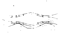
下面将结合附图中所示的实施例,更详细地说明本发明的主题,其中:The subject matter of the present invention will be described in more detail below with reference to the embodiments shown in the accompanying drawings, wherein:
图1示出了本发明装置的前视图;Fig. 1 shows the front view of the device of the present invention;
图2示出了在容器的两个部件被相互锁定的情况下的输送容器的锁定机构;Figure 2 shows the locking mechanism of the delivery container with the two parts of the container locked to each other;
图2a示出了在两个容器部件可以分别相对于对方枢转到打开位置情况下的所述锁定机构;Figure 2a shows the locking mechanism in a situation where the two container parts can each be pivoted relative to each other into an open position;
图3是以比图1更大的比例示出容器的底部部分的侧视图;Figure 3 is a side view showing the bottom portion of the container on a larger scale than in Figure 1;
图4示出了所述本发明装置的平面视图。Figure 4 shows a plan view of the device according to the invention.
图1中所示的输送装置在其末端处具有一个长方体形的承载支承框架1,在该框架的下方可以停放装载散装物品的运输车辆。输送装置包含多个输送容器2,这些容器设置于承载支承杆20的底端。运行齿轮机构31和夹紧装置32被设置在承载杆20的顶端。利用夹紧装置32,带有容器2的承载支承杆20可以与输送缆3相联。输送缆3的移动可以从输送装置起点处移动容器2,在此,散装物品从上方提供,这样容器2一直被移送到输送装置的末端,在末端处,容器2中所盛放的散装物品被排放到运输车辆、存贮容器或者是类似物中。The conveyor device shown in FIG. 1 has at its ends a cuboid-
有关运行齿轮机构31和夹紧装置32的设计可以从运送人用的缆车的结构中了解到。The design of the relevant
由于输送容器2的顶端是打开的,所以可以从上方装填散装物品。为使散装物品可在输送装置的末端处从容器2中放出,所述容器可以被大致垂直地分成两个部件21,22,利用锁定机构4,两个容器部件21,22可以被保持在关闭位置上,其结果是,容器2被准备好以接收散装物品。同时设置控制机构5,利用这个装置,两个容器部件21,22可在输送装置的末端处彼此枢转分离,结果是,所述容器部件的漏斗形基部被打开,从而散装物品能够朝下流出。Since the top end of the
如图2中所示,锁定机构4具有紧固在容器部件21下方的承载框架41,并且在锁定机构4上安装有2个锁定爪43,其受到压缩弹簧44的作用。利用该弹簧,两个锁定爪可以相对枢转。调整杠杆47的自由端侧安装有控制辊48,该杠杆同锁定爪43铰接,杠杆与锁定爪之间有可自由移动的第一连杆22,和安装在承载支承框架41上的第二连杆46。As shown in FIG. 2 , the
锁定在第二容器部件下方的是第二承载支承框架42,其上伸出一个锁定杆49,在该锁定杆的自由端上有三角形的锁定元件49a,在其后方连接有设计与锁定元件相匹配的锁定爪43。Locked below the second container part is a second load-bearing
图2示出了两个容器部件21和22的位置,其中,所述容器部件正处于关闭位置上,利用锁定机构4可将容器部件保持在该位置上。这就意味着输送容器2的底部是关闭的,且可以从上方将散装物品装入所述容器。在输送装置的末端处安装有控制轨道,控制辊在轨道上运动,其结果是,调整杠杆47在箭头A的方向上枢转。这使得锁定爪43被枢转到其打开位置,同弹簧44的作用正好相反,结果是其释放开锁定杆49。调整杠杆47的该位置以及锁定爪43的位置如图2a中所示,一旦两个容器部件21和22彼此枢转分离,容器2的底部就被打开,结果使容器中的散装物品向下流出。FIG. 2 shows the position of the two
两个容器部件21和22受控制机构5的控制彼此枢转分离,以下将结合图3和图4加以解释。杆51和52自两个容器部件21和22向下伸出。在杆的自由端分别安装有控制辊53和54。另外作为导向件的控制轨道55和56设置在输送装置的末端处,其作用是对两个容器部件21和22的运动进行控制。The two
如在图4中所见到的,控制轨道40设置在承载支架1的顶端,并且该控制导轨专用于调整杠杆47的控制辊48。在承载支架1的顶侧还有两个导向件55和56,用于分别引导安装在杆51和52上的控制辊53和54,为此,导向件55和56被设计成具有漏斗形引导开口。As can be seen in FIG. 4 , a
本输送装置的操作如下所述:The operation of the delivery unit is as follows:
在输送装置的起始位置上,容器的21和22两个部分彼此锁定在一起,结果是输送容器2的底部被关闭。因此,可以将散装物品从上方装入到所述容器当中。此后,容器2同持续循环的传输缆3相联,从而可沿所述输送装置移动。在输送装置的末端处,容器2同输送缆3脱离接合并沿导轨移动,其移动速度低于输送缆3的速度,一直移进到位于承载支架1上方的控制区中。In the starting position of the delivery device, the two
在这种情况下,一方面,控制辊48在导轨40上运行,结果使调整杠杆47枢转到如图2a所示的位置之上。这使得两个容器部件21和22能够彼此松开。另一方面,控制辊53和54进入导向件55和56,这使得两个容器部件21和22利用在导向件55和56中的控制辊53和54彼此枢转分离,其结果是,相关容器2的底部被打开,使容纳于容器中的散装物品向下流出。In this case, on the one hand, the
由于承载支承框架1被设计为在此区域有一个向下的开口,所以散装物品可以进入到另一个容器,即进入到运输车辆的容器之中或者是存储容器之中,所述这些容器位于承载支承框架1的下方。Since the load-bearing
这样就设计出本发明的装置,其能够保证对输送装置的输送容器进行在自动的和精确控制下的排空操作。The device according to the invention has thus been devised which ensures an automatic and precisely controlled emptying of the delivery container of the delivery device.
Claims (7)
Applications Claiming Priority (2)
| Application Number | Priority Date | Filing Date | Title |
|---|---|---|---|
| ATA1215/98 | 1998-07-14 | ||
| AT0121598A AT409116B (en) | 1998-07-14 | 1998-07-14 | SYSTEM FOR THE TRANSPORT OF BULK MATERIAL |
Publications (2)
| Publication Number | Publication Date |
|---|---|
| CN1241509A true CN1241509A (en) | 2000-01-19 |
| CN1094881C CN1094881C (en) | 2002-11-27 |
Family
ID=3509110
Family Applications (1)
| Application Number | Title | Priority Date | Filing Date |
|---|---|---|---|
| CN99105832A Expired - Fee Related CN1094881C (en) | 1998-07-14 | 1999-04-20 | Installation for transporting bulk material |
Country Status (6)
| Country | Link |
|---|---|
| EP (1) | EP0972728B1 (en) |
| CN (1) | CN1094881C (en) |
| AT (2) | AT409116B (en) |
| BR (2) | BR9901404A (en) |
| DE (1) | DE59901838D1 (en) |
| ES (1) | ES2177214T3 (en) |
Families Citing this family (3)
| Publication number | Priority date | Publication date | Assignee | Title |
|---|---|---|---|---|
| PT1538112E (en) * | 2003-12-04 | 2006-06-30 | Innova Patent Gmbh | INSTALLATION FOR THE TRANSPORTATION OF MATERIALS THROUGH A WIDELESS CONVEYOR BELT |
| DE102010052094B4 (en) | 2010-11-20 | 2020-04-23 | Zeppelin Systems Gmbh | Cable car-supported transport system for bulk goods with dirt-protected bulk goods containers |
| CN108190287B (en) * | 2017-12-13 | 2019-11-08 | 煤炭科学技术研究院有限公司 | An opening and closing control device for a hopper door |
Family Cites Families (6)
| Publication number | Priority date | Publication date | Assignee | Title |
|---|---|---|---|---|
| FR353311A (en) * | 1905-03-25 | 1905-09-08 | Alfred Paris | aerial lift |
| JPS56149909A (en) * | 1980-04-22 | 1981-11-20 | Komatsu Ltd | Gravity type conveying apparatus |
| JP2629041B2 (en) * | 1989-02-14 | 1997-07-09 | 株式会社吉野工業所 | Reversing mechanism |
| JPH02265811A (en) * | 1989-04-07 | 1990-10-30 | Sagawa Butsuriyuu Service Kk | High and low speed automatic sorting conveyer |
| US5346052A (en) * | 1993-04-23 | 1994-09-13 | Fox Harvey Z | Feed bucket for programmed delivery system |
| CN1177916A (en) * | 1995-03-06 | 1998-04-01 | 森特拉苏格股份公司 | Device for emptying trays |
-
1998
- 1998-07-14 AT AT0121598A patent/AT409116B/en not_active IP Right Cessation
-
1999
- 1999-02-05 DE DE59901838T patent/DE59901838D1/en not_active Expired - Lifetime
- 1999-02-05 EP EP99890042A patent/EP0972728B1/en not_active Expired - Lifetime
- 1999-02-05 AT AT99890042T patent/ATE219748T1/en active
- 1999-02-05 ES ES99890042T patent/ES2177214T3/en not_active Expired - Lifetime
- 1999-04-20 CN CN99105832A patent/CN1094881C/en not_active Expired - Fee Related
- 1999-04-26 BR BR9901404-1A patent/BR9901404A/en not_active IP Right Cessation
-
2002
- 2002-08-21 BR BRPI0203379-8A patent/BR0203379B1/en not_active IP Right Cessation
Also Published As
| Publication number | Publication date |
|---|---|
| EP0972728B1 (en) | 2002-06-26 |
| EP0972728A1 (en) | 2000-01-19 |
| DE59901838D1 (en) | 2002-08-01 |
| BR9901404A (en) | 2000-04-25 |
| BR0203379A (en) | 2003-05-20 |
| ES2177214T3 (en) | 2002-12-01 |
| AT409116B (en) | 2002-05-27 |
| ATA121598A (en) | 2001-10-15 |
| BR0203379B1 (en) | 2010-09-21 |
| CN1094881C (en) | 2002-11-27 |
| ATE219748T1 (en) | 2002-07-15 |
Similar Documents
| Publication | Publication Date | Title |
|---|---|---|
| EP3782936B1 (en) | Transport bag for overhead conveyor system | |
| US5101983A (en) | Device for identifying and sorting objects | |
| JP3323205B2 (en) | Object transport device | |
| US4063656A (en) | System and apparatus for moving and unloading articles | |
| EP0806384A2 (en) | A conveying system | |
| EP4168334B1 (en) | Transport bag for suspended transport of material to be conveyed, and loading station and conveyor system for these transport bags | |
| JP3609120B2 (en) | Folded fabric product carrying holder and carrying device | |
| US5348132A (en) | Carriage for a conveyor for piece goods | |
| US3042186A (en) | Conveying apparatus for individual objects | |
| US11878876B2 (en) | Device for emptying transport bags conveyed in a suspended manner | |
| JP2002505244A (en) | Product Dimension Classification Transport Mechanism | |
| US20210395022A1 (en) | Method and device for opening a transport bag | |
| US3476089A (en) | Poultry loading device | |
| CN1241509A (en) | Installation for transporting bulk material | |
| EP0496475A1 (en) | Conveyor- and distribution plant | |
| US4565203A (en) | Apparatus for conveying cigarette-filled trays to a cigarette-packaging machine | |
| CA2242546A1 (en) | Apparatus for sorting or selectively collecting flat products individually supplied by a conveyor | |
| EP0516709A1 (en) | Apparatus and method for sorting and distributing mail | |
| EP0095573B1 (en) | Newspaper container unloading apparatus | |
| KR100335646B1 (en) | Rail transfer system | |
| JPH0756252Y2 (en) | Goods sorting equipment | |
| US1585234A (en) | Conveyer system | |
| KR100433088B1 (en) | Device for transporting objects without slipping, fixed on vehicles with loading surface | |
| KR102811938B1 (en) | Feed conveying and feeding device for trolley conveyors | |
| CZ288960B6 (en) | Sorting box system for sawn timber or similar goods |
Legal Events
| Date | Code | Title | Description |
|---|---|---|---|
| C06 | Publication | ||
| PB01 | Publication | ||
| C10 | Entry into substantive examination | ||
| SE01 | Entry into force of request for substantive examination | ||
| C53 | Correction of patent of invention or patent application | ||
| CB02 | Change of applicant information |
Applicant after: Innova Patent GmbH Applicant before: Konrad Doppelmayr & Sohn Maschinenfabrik Gesellschaft m. b. H. & Co. KG |
|
| COR | Change of bibliographic data |
Free format text: CORRECT: APPLICANT; FROM: KONRAD DOPPELMAYR + SOHN MSCHINENFABRIK GESELLSCHAFT + CO. KG TO: INNOVA PATENT GMBH |
|
| C14 | Grant of patent or utility model | ||
| GR01 | Patent grant | ||
| REG | Reference to a national code |
Ref country code: HK Ref legal event code: GR Ref document number: 1058138 Country of ref document: HK |
|
| CF01 | Termination of patent right due to non-payment of annual fee |
Granted publication date: 20021127 Termination date: 20180420 |
|
| CF01 | Termination of patent right due to non-payment of annual fee |