CN1246111C - Gravity Type Tiltable Metal Die Casting Machine - Google Patents
Gravity Type Tiltable Metal Die Casting Machine Download PDFInfo
- Publication number
- CN1246111C CN1246111C CNB028001095A CN02800109A CN1246111C CN 1246111 C CN1246111 C CN 1246111C CN B028001095 A CNB028001095 A CN B028001095A CN 02800109 A CN02800109 A CN 02800109A CN 1246111 C CN1246111 C CN 1246111C
- Authority
- CN
- China
- Prior art keywords
- metal
- mold
- main
- die
- rotation
- Prior art date
- Legal status (The legal status is an assumption and is not a legal conclusion. Google has not performed a legal analysis and makes no representation as to the accuracy of the status listed.)
- Expired - Lifetime
Links
Images




Classifications
-
- B—PERFORMING OPERATIONS; TRANSPORTING
- B22—CASTING; POWDER METALLURGY
- B22D—CASTING OF METALS; CASTING OF OTHER SUBSTANCES BY THE SAME PROCESSES OR DEVICES
- B22D23/00—Casting processes not provided for in groups B22D1/00 - B22D21/00
- B22D23/006—Casting by filling the mould through rotation of the mould together with a molten metal holding recipient, about a common axis
Landscapes
- Engineering & Computer Science (AREA)
- Mechanical Engineering (AREA)
- Molds, Cores, And Manufacturing Methods Thereof (AREA)
- Casting Devices For Molds (AREA)
- Working Measures On Existing Buildindgs (AREA)
Abstract
Description
技术领域technical field
本发明涉及重力型可倾斜的金属模铸造机械,其中熔化的金属(例如,铝)当它们被倾斜时被倒入由金属上模和金属下模所形成的模腔中。The present invention relates to gravity-type tiltable metal mold casting machines in which molten metal (for example, aluminum) is poured into mold cavities formed by metal upper and lower metal molds as they are tilted.
背景技术Background technique
在JPH 5-31809A中公开了这种传统的重力型可倾斜金属模铸造机械。此机械是这样构造的,整个铸造机械的旋转和金属上模(即,释放金属下模的上开口)的旋转二者是绕公共轴线(处于金属上模和下模装配体外面的旋转轴线)而进行。This conventional gravity type tiltable metal mold casting machine is disclosed in JPH 5-31809A. The machine is constructed such that the rotation of the entire casting machine and the rotation of the metal upper mold (i.e. the upper opening that releases the metal lower mold) are both about a common axis (axis of rotation outside the metal upper and lower mold assembly) And proceed.
由于在此机械中机械的旋转轴线和金属上模的旋转轴线是相同的,旋转的单一轴线必须处于金属上模和下模装配体的外面,从而当打开金属上模时使上下模的上部完全打开。因此,当铸模被倾斜且熔化的金属倒入其中时,铸模装配体的中心在远离旋转轴线的一个位置旋转,因而对铸模中的熔化金属流作用一个大的旋转惯性。铸模装配体中的具有大的转动惯性的熔化金属流趋于涡动并因此趋于包卷空气,因此产生氧化膜,并趋于包卷该膜。为防止此膜产生并被包卷,必须这样移动铸模装配体,它将不具有大的转动惯性。但是,在上述机械中,该机械具有铸模装配体外面的旋转轴线,通过使机械的倾斜半径最小以降低其圆周速度转动惯性可被降低到一定的范围。这引起一个问题在于机械倾斜冲程的周期必须被延长。Since the axis of rotation of the machine and the axis of rotation of the metal upper mold are the same in this machine, the single axis of rotation must be outside the assembly of the metal upper mold and the lower mold, so that when the metal upper mold is opened, the upper part of the upper and lower molds is completely closed. Open. Therefore, when the mold is tilted and molten metal is poured into it, the center of the mold assembly rotates at a position away from the axis of rotation, thereby acting a large rotational inertia on the flow of molten metal in the mold. A flow of molten metal in a mold assembly with a large rotational inertia tends to swirl and thus tends to enclose air, thus creating an oxide film, and tends to enclose the film. To prevent this film from being generated and wrapped up, the mold assembly must be moved such that it will not have a large moment of inertia. However, in the above machine, which has the axis of rotation outside the mold assembly, the rotational inertia can be reduced to a certain extent by minimizing the inclination radius of the machine to reduce its peripheral speed. This causes a problem in that the period of the mechanical tilt stroke has to be extended.
此外,由于最小化机械的倾斜半径中的限制,以及由于降低上模和紧固上模与下模的缸和驱动机构以将铸造产品推出的缸被对准,处于下模以下的装置是固有地长,同时机械固有地具有大的倾斜半径(即,大的转动惯性)。因此必须准备大的空间以安装该机械。此外,还有另一问题在于从机械的安装表面到金属下模的高度是很大的。这就使放芯子在下模中以及取出铸造产品的操作困难。因此机械需要一个凹坑或工作台以便易于实行这些操作。Furthermore, due to constraints in minimizing the tilting radius of the machine, and due to the alignment of the cylinders and drive mechanisms for lowering and fastening the upper and lower dies to push out the cast product, the means below the lower die are inherently Long, while the machine inherently has a large tilt radius (ie, large rotational inertia). Therefore, a large space must be prepared to install the machine. In addition, there is another problem in that the height from the mounting surface of the machine to the metal lower die is large. This makes the operation of putting the core in the lower mold and taking out the cast product difficult. The machine therefore needs a pit or table to facilitate these operations.
发明内容Contents of the invention
本发明的目的就是提供一种重力型可倾斜的金属模铸造机械,该机械不需要为了防止空气和氧化膜被包卷入熔化的金属中而延长倾斜行程的周期,该机械具有铸模装配体的最小化的倾斜半径因此控制其圆周速度比较低,它自身具有最小化的倾斜半径和低的外形,因此机械是紧凑的,当打开上模时通过释放下模的上开口而给予上模以通路,该机械可降低为其安装而不妨碍在金属下模中放芯子和取出铸造产品的操作所需的空间,同时该机械不要准备凹坑而可被安装。The object of the present invention is to provide a gravity type tiltable metal mold casting machine, which does not need to prolong the period of the tilting stroke in order to prevent air and oxide films from being entrained in the molten metal, and which has a mold assembly Minimized inclination radius so that its peripheral speed is relatively low, it has a minimized inclination radius and low profile, so the machine is compact, and when the upper mold is opened, it gives access to the upper mold by releasing the upper opening of the lower mold , the machine can reduce the space required for its installation without interfering with the operations of putting the core in the metal lower mold and taking out the casting product, and at the same time the machine can be installed without preparing a cavity.
为此,本发明提供了一种重力型可倾斜的金属模铸造机械,包括:一对相对直立的支承框架;一对相对的主旋转轴,设置在旋转轴线上并可旋转地安装在直立支承框架上端;主框架,固定地安装在主旋转轴上,使得该主框架下垂地悬挂于主旋转轴之间;电机,安装在旋转轴之一上,以便可逆向地旋转主旋转轴并因此旋转框架;下模板,由安装在主框架的下部的铸模紧固缸垂直移动;金属下模,固定到下模板,该金属下模具有下模推出机构,用于将铸造产品推出金属下模;一对相对的上模倾斜轴,水平设置在水平轴线上并在主旋转轴的背向位置固定到主框架上端;上模安装框架,可旋转地安装在上模倾斜轴一端处;上模板,固定到上模安装框架的下表面上;以及固定到上模板上的金属上模,该金属上模具有上模推出机构以便将铸造产品推出金属上模;铁水包,绕旋转水平轴线可旋转地安装,旋转水平轴线处在金属上模和下模装配体的后面;以及一个电机,用于绕旋转的水平轴线可逆地旋转铁水包;其中,金属上模和下模装配体的中心基本上位于主旋转轴的旋转轴线上。To this end, the present invention provides a gravity-type tiltable metal mold casting machine, comprising: a pair of relatively upright support frames; a pair of relative main rotating shafts, arranged on the axis of rotation and rotatably mounted on the upright supports the upper end of the frame; the main frame, fixedly mounted on the main rotating shafts such that the main frame hangs pendulously between the main rotating shafts; the motor, mounted on one of the rotating shafts so as to reversibly rotate the main rotating shaft and thereby rotate frame; the lower template, which is vertically moved by the mold fastening cylinder installed on the lower part of the main frame; the metal lower mold, which is fixed to the lower template, and the metal lower mold has a lower mold pushing mechanism for pushing the casting product out of the metal lower mold; For the opposite upper mold tilt axis, it is horizontally arranged on the horizontal axis and fixed to the upper end of the main frame at the back position of the main rotation axis; the upper mold installation frame is rotatably installed at one end of the upper mold tilt axis; the upper mold, fixed to the lower surface of the upper mold mounting frame; and a metal upper mold fixed to the upper mold plate, the metal upper mold having an upper mold push-out mechanism for pushing the cast product out of the metal upper mold; a ladle, rotatably mounted about a horizontal axis of rotation , the horizontal axis of rotation is behind the metal upper and lower die assembly; and a motor for reversibly rotating the ladle about the horizontal axis of rotation; wherein the metal upper and lower die assembly is centered substantially on the main on the axis of rotation of the axis of rotation.
附图说明Description of drawings
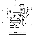
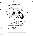
图1是本发明的重力型可倾斜的金属模铸造机械的实施例的示意正视图。Fig. 1 is a schematic front view of an embodiment of the gravity type tiltable metal mold casting machine of the present invention.
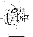
图2是图1所示的机械的侧视图。FIG. 2 is a side view of the machine shown in FIG. 1 .
图3是图1所示的旋转铁水包机构的横剖视图。Fig. 3 is a cross-sectional view of the rotating ladle mechanism shown in Fig. 1 .
图4是旋转铁水包机构的垂直剖视图。Fig. 4 is a vertical sectional view of the rotating ladle mechanism.
图5是类似于图2的侧视图,表示已经固定在机械上的上模和下模。Figure 5 is a side view similar to Figure 2 showing the upper and lower molds already secured to the machine.
图6是侧视图,表示已经从其图5所示之位置被降低并分开的下模。Fig. 6 is a side view showing the lower mold which has been lowered and separated from its position shown in Fig. 5 .
图7是侧视图,表示从其图6所示之位置绕上模倾斜轴顺时针转90°的上模。Fig. 7 is a side view showing the upper die rotated 90° clockwise around the upper die tilt axis from its position shown in Fig. 6 .
图8是侧视图,表示从其图7所示之位置逆时针转90°然后锁紧的上模。Figure 8 is a side view showing the upper mold turned 90° counterclockwise from its position shown in Figure 7 and then locked.
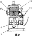
图9是侧视图,表示从其图8所示之位置升高并紧固到上模上的下模。Figure 9 is a side view showing the lower mold raised from its position shown in Figure 8 and secured to the upper mold.
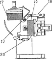
图10是侧视图,表示安装到机械的主框架上逆时针转90°以便从其图9所示之位置倾倒熔化的金属的整个装置。Figure 10 is a side view showing the entire apparatus mounted on the main frame of the machine turned 90° counterclockwise for pouring molten metal from its position shown in Figure 9.
图11是侧视图,表示被从上模从其图10所示之位置分开的下模。Fig. 11 is a side view showing the lower die separated from the upper die from its position shown in Fig. 10 .
图12是侧视图,表示从其图11所示之位置绕上模的倾斜轴顺时针转动90°的上模。Fig. 12 is a side view showing the upper die rotated 90° clockwise about the tilt axis of the upper die from its position shown in Fig. 11.
图13是侧视图,表示主框架从其图10所示之位置转回到其垂直位置。Figure 13 is a side view showing the main frame rotated from its position shown in Figure 10 back to its vertical position.
图14是侧视图1表示从其图13所示之位置被降低的下模。Figure 14 is a side view 1 showing the lower mold being lowered from its position shown in Figure 13 .
图15是侧视图,表示从其图14所示之位置绕上模倾斜轴旋转的上模。Fig. 15 is a side view showing the upper die rotated about the upper die tilt axis from its position shown in Fig. 14 .
具体实施方式Detailed ways
以下对本发明的实施例通过参考附图详细说明。在图1和2中一对相对直立的框架2、2被安装在基座1上。一对相对的主旋转轴3、3被设置在轴线上并可旋转地安装在直立框架2、2的上端。主框架4这样固定地安装在主旋转轴3、3上,即主框架从主旋转轴下垂并在它们之间被悬挂。为了可逆地旋转主框架4A,主电机19,诸如伺服电机,安装在支承框架的一个上。为可逆地旋转主框架4的主电机19连接到主旋转轴3、3的一根的一端上。Embodiments of the present invention are described in detail below with reference to the accompanying drawings. In FIGS. 1 and 2 a pair of relatively
为紧固铸模,若干面向上的缸5、5安装在主框架4的下部。一个下模板6被固定到铸模紧固缸5、5的活塞杆的末端。空心导向杆7连接到下模板6的下表面的中央部分。空心导向杆7在导向管8中垂直地滑动。该管固定到主框架4的下部,以便导向被垂直移动的下模板6。
金属下模10,该下模具有一下模推出机构23以便从下模10中推出铸造产品,由下模夹子25、25固定到下模板上,该下模夹子在金属下模10的二侧安装在下模板上。此外,为致动下模推出机构23的下模推出缸12设置在空心导向杆7里面,同时下模推出板24连接到下模推出缸12的活塞杆的末端。下模推出板24经过下模模板6的中央开口是垂直可移动的并且通过任何已知的装置可拆卸地连接到下模推出机构23上。Metal
水平地在一轴线上延伸的一对相对的上模倾斜轴13、13在主旋转轴3、3的背向位置安装到主框架4的上端。上模安装框架14可旋转地安装到上模倾斜轴13、13上的一端。A pair of opposing upper mold tilting
上模板16安装到上模安装框架14的下表面上,而金属上模17通过在金属上模17的二侧安装在上模板16上的上模夹子27、27固定到上模板16的下表面上。该金属上模17具有上模推出机构以便将铸造产品推出金属上模17。此外,为致动上模推出机构26的面向下的缸28安装在上模安装框架14上。上模推出板29连接到上模推出缸28的活塞杆的末端。下模推板29经过上模板16的中央开口是垂直可移动的。若干导向杆30、30安装在上模推板29上。导向杆30、30在固定到上模安装框架14上的导向管31、31中滑动,以便导向上模推板29垂直地移动。
图中的标号18、18表示为可逆地转动金属上模17的缸,而标号20、20表示为紧固金属上模在适当位置的锁紧缸。
在图3和4中说明铁水包转动机构11。铁水包21以其末端插入模腔31中而设置,该模腔由上模17和下模10当它们彼此被连接时(即,当它们被紧固)所确定。铁水包21固定地被安装到一对铁水包支承框架32、32上。铁水包支承框架又被可旋转地安装到一对臂的末端上,该臂固定地安装在主框架4上,通过一对相对的、彼此在水平轴线上对准的铁水包旋转轴34、34。铁水包旋转轴34、34的一根被连接到电机9上(诸如伺服电机)以便通过链条35可逆地转动铁水包21。The
在铁水包旋转机构11的操作中,能可逆地旋转铁水包的旋转电机9旋转铁水包的旋转轴34、34并因此转动铁水包支承框架32、32和铁水包21。由于铁水包21的末端处在铁水包旋转轴34、34的轴线上,所以铁水包21绕其末端旋转。In operation of the
此外,如在图1中见到的,在本发明的重力型可倾斜的金属模铸造机械中上模和下模装配体(即,当它们连接成装配体时)的中心基本上是在主旋转轴3、3的旋转的共同轴线上。因此,为了旋转主框架4,当上模和下模装配体被主电机19旋转时,它基本上绕主旋转轴3、3的旋转公共轴线旋转。In addition, as seen in FIG. 1, in the gravity type tiltable metal mold casting machine of the present invention, the centers of the upper mold and the lower mold assembly (that is, when they are connected into the assembly) are substantially at the center of the main body. On the common axis of rotation of the
关于上述构形的重力型可倾斜的金属模铸造机械的操作,现在参照图5-15加以说明。The operation of the gravity type tiltable metal mold casting machine of the above configuration will now be described with reference to Figs. 5-15.
首先参照图5-12说明当铸造产品保持在上模17中时,取出该铸造产品的操作。首先,一组金属上模17和金属下模10被放置在本发明的重力型可倾斜的金属模铸造机械上。然后,上模夹子27、27和下模夹子25、25被夹紧以便分别地将金属上模17和下模10固定到上模板16和下模模板上。First, the operation of taking out the cast product while the cast product is held in the
从图5的状态然后运转铸模紧固缸5、5以便缩回它们的活塞杆以降低并从金属下模10分开金属上模17,如图6所示。From the state of FIG. 5 the
然后运转锁紧缸20、20以便松开金属上模17,然后运转为可逆地旋转金属上模17的缸18、18以便顺时针绕上模倾斜轴13、13旋转金属上模90°,如图7所示。Then run the locking
然后进行诸如在金属下模中放芯子等的辅助操作,在那些操作之后,缸18、18运转以便逆时针旋转金属上模,然后反向地运转锁紧缸20、20以便锁紧金属上模,如图8所示。Auxiliary operations such as placing the core in the lower metal mold are then performed, after those operations the
然后铸模紧固缸运转以伸出它们的活塞杆以便将金属下模10紧固到金属上模17上。The mold fastening cylinders are then operated to extend their piston rods in order to fasten the
然后铁水包放置熔化的铝金属,同时主电机随后运转以便绕主旋转轴3、3转动使安装到主框架4上的整个装置逆时针转90°,如图10所示。由于装置在此旋转过程中,通过该旋转熔化的金属倒入上模与下模装配体的模腔中,装配体绕其中心旋转,由其摆动引起的其转动惯性被最小化。换句话说,装配体以其可能最低的圆周速度旋转。因而,这就不会以大的惯性作用到倒入模腔中的熔化的金属,因此在模腔中引起熔化金属较小的回弹或摇晃,同时防止空气和氧化膜被包卷入熔化的金属中。因此,它被平稳地倒入模腔中。Then the molten aluminum metal is placed on the ladle, and the main motor is then operated so as to rotate around the main
如果铁水包21未被铁水包旋转电机9相对于上模和下模装配体旋转,从铁水包21被倒入模腔31中的熔化的铝金属的量将仅受装配体旋转角度的限定,同时在其给定的旋转角度可以被倒入上模和下模装配体的腔31的熔化的铝金属的量将受腔31的形状的限定。然而,当上模和下模装配体被旋转时如果铁水包21被铁水包旋转电机适当地顺时针或逆时针旋转从而将需要的、适当的熔化的金属量倒入腔31中,需要的、适当的熔化的金属量被倾倒,同时防止空气和氧化膜在熔化的金属中被包卷,因此允许平稳的倾倒。If the
在上模与下模装配体以及铁水包21分别地被电机19和铁水包旋转电机9旋转之后,图10所示装配体的位置保持一给定的时间间隔直到熔化的金属固化。After the upper and lower mold assembly and the
然后下模推出缸12伸展以升高下模推板24,以便致动下模推出机构23,同时缩回铸模紧固缸5、5以便从金属上模17上分离金属下模10。在此分离时铸造的产品从金属下模10上除去并被金属上模17保持。然后锁紧缸20、20运转以松开金属上模17,然后缸18、18运转以便绕上模倾斜轴13、13旋转金属上模17,如图12所示。上模推出缸28然后伸出以推下上模推板以便致动上模推出机构26,因而从金属上模17中取出铸造产品。取出的铸造产品由产品取出装置(均未表示)的托盘接受。The lower
然后主电机19运转以旋转架4,如图7所示,为下一个清理金属上模17和下模10,在金属下模10上放芯子等的辅助处理。上述有关图7-12说明的操作被重复。Then
现在说明取出保持在金属下模10中的铸造产品的操作。进行上述有关图5-10说明的过程。然后主电机19运转以便绕主旋转轴3、3旋转主框架4至图13所示的直立位置。然后上模推出缸28伸展以推动上模推板29以便致动上模推出机构26,同时铸模紧固缸5、5缩回以便从金属上模17上分开金属模板10,如图14所示。在此分开期间铸造产品由金属下模10保持。The operation of taking out the cast product held in the metal
然后锁紧缸20、20运转以松开上模17,然后缸18、18运转以便绕上模倾斜轴13、13旋转金属上模17。下模推出缸12然后伸展以推动下模推板24以便致动下模推出机构23,同时由产品取出装置(未表示)取出铸造的产品,如图15所示、然后进行清理金属上模和下模,在金属下模中放芯子等辅助过程,然后重复以上操作。The locking
实施例的主框架4可以通过放置止动器(未表示)而置于适当位置,但当它被转动时除外。The
应该理解,上述实施例仅仅是为了举例,同时可对它们作许多变化。因此本发明包括这些变化,而本发明的范围由所附权利要求书确定。It should be understood that the above-described embodiments are by way of example only, and that many variations can be made to them. The invention therefore embraces such changes, and the scope of the invention is determined by the appended claims.
例如,在上述实施例中,上模板16是可旋转的,同时下模模板6是直线移动的。但实际上上述二种板16、6的运动不受这些运动的限制,同时,例如,下模模板6可以是可旋转的,而上模板16可以直线移动。For example, in the above-described embodiment, the
如以上讨论的,由于在此发明中金属上模绕处于铸模装配体的旋转轴线后面的水平轴线而旋转,金属下模能被打开以便当金属上模打开时容易地进入。As discussed above, since the upper metal mold in this invention rotates about a horizontal axis behind the axis of rotation of the mold assembly, the lower metal mold can be opened for easy access when the upper metal mold is open.
此外,由于上模和模型装配体基本上绕该装配体的中心而倾斜,当倾斜时它将具有低的旋转惯性,造成熔化金属的小的回弹和摇晃。此外,由于铁水包独立于铸模装配体的旋转而被电机旋转,足够的(但不过量)和需要的熔化的金属量被倒入模腔中,因此防止空气和氧化膜在熔化的金属中被包卷。此外,由于铸模装配体的摇摆被最小化,机械可以紧凑。此外,使用电机(诸如伺服电机)以倾斜铸模装配体,而不用传统的油压缸,允许装配体精确地倾斜,因此能使倾斜运动重复,该倾斜运动可以存储在记忆装置中同时当需要时随时可调用。Furthermore, since the upper die and model assembly is substantially tilted about the center of the assembly, it will have low rotational inertia when tilted, causing little rebound and shaking of the molten metal. In addition, since the ladle is rotated by the motor independently of the rotation of the mold assembly, sufficient (but not excessive) and required amount of molten metal is poured into the cavity, thus preventing air and oxide films from being trapped in the molten metal. wrapped rolls. Furthermore, since the sway of the molded assembly is minimized, the machine can be compact. In addition, the use of a motor (such as a servo motor) to tilt the molded assembly, rather than conventional hydraulic cylinders, allows the assembly to be tilted precisely, thus enabling repeatable tilting motions that can be stored in memory and when needed Available anytime.
此外,由于在本发明中导向上模板的垂直运动的导向杆是空心的,同时为将铸造产品推出下模的下模推出缸被设置在空心导向杆内,在下模以下放置的装置可以是低的外形,因此允许操作者进行在下模中放芯子和从金属上模或下模中取出铸造产品的操作而不用准备凹坑或工作台。In addition, since the guide bar for guiding the vertical movement of the upper mold plate is hollow in the present invention, and the lower mold ejection cylinder for pushing the cast product out of the lower mold is set in the hollow guide bar, the device placed under the lower mold can be low. shape, thus allowing the operator to carry out the operation of placing the core in the lower mold and removing the cast product from the metal upper or lower mold without preparing a pit or table.
Claims (2)
Applications Claiming Priority (3)
| Application Number | Priority Date | Filing Date | Title |
|---|---|---|---|
| JP007266/01 | 2001-01-16 | ||
| JP007266/2001 | 2001-01-16 | ||
| JP2001007266A JP3722356B2 (en) | 2000-08-10 | 2001-01-16 | Gravity tilting die casting machine |
Publications (2)
| Publication Number | Publication Date |
|---|---|
| CN1455713A CN1455713A (en) | 2003-11-12 |
| CN1246111C true CN1246111C (en) | 2006-03-22 |
Family
ID=18875042
Family Applications (1)
| Application Number | Title | Priority Date | Filing Date |
|---|---|---|---|
| CNB028001095A Expired - Lifetime CN1246111C (en) | 2001-01-16 | 2002-01-16 | Gravity Type Tiltable Metal Die Casting Machine |
Country Status (9)
| Country | Link |
|---|---|
| US (1) | US6942010B2 (en) |
| EP (1) | EP1351788B1 (en) |
| CN (1) | CN1246111C (en) |
| AT (1) | ATE355922T1 (en) |
| BR (1) | BR0203647B1 (en) |
| DE (1) | DE60218630T2 (en) |
| ES (1) | ES2283539T3 (en) |
| MX (1) | MXPA03006351A (en) |
| WO (1) | WO2002055237A1 (en) |
Cited By (1)
| Publication number | Priority date | Publication date | Assignee | Title |
|---|---|---|---|---|
| CN111615435A (en) * | 2017-12-28 | 2020-09-01 | Ksm铸造集团有限公司 | Tilt casting machine |
Families Citing this family (20)
| Publication number | Priority date | Publication date | Assignee | Title |
|---|---|---|---|---|
| ITPD20030115A1 (en) * | 2003-05-27 | 2004-11-28 | Imr Spa | GRAVITY CASTING PLANT WITH FORMING SHELL |
| TWI386262B (en) * | 2004-09-01 | 2013-02-21 | Commw Scient Ind Res Org | Alloy casting apparatus |
| JP4411219B2 (en) * | 2005-01-18 | 2010-02-10 | 光生アルミニューム工業株式会社 | 3D casting machine and 3D casting method |
| JP2007061847A (en) * | 2005-08-31 | 2007-03-15 | Sintokogio Ltd | Mold casting equipment in casting equipment |
| CN101234422B (en) * | 2008-03-04 | 2010-06-09 | 林爱道 | Worktable control device for gravity force casting machine |
| DE102010022343B4 (en) * | 2010-06-01 | 2017-10-26 | Volkswagen Ag | Method for tilt casting of components and tilt casting device |
| CN103658561A (en) * | 2012-09-05 | 2014-03-26 | 戴辉 | Casting sand mold locking clamp |
| CN103157782B (en) * | 2013-04-03 | 2015-03-04 | 苏州苏铸成套装备制造有限公司 | Three-axis association full-automatic casting machine |
| CN104439217B (en) * | 2014-12-18 | 2016-08-17 | 济南圣元机械工程有限公司 | A kind of fixed Gravity casting machines |
| MX357777B (en) | 2014-12-24 | 2018-07-19 | Sintokogio Ltd | FOUNDRY DEVICE AND MOLD REPLACEMENT METHOD FOR FOUNDRY DEVICE. |
| JP1540723S (en) * | 2015-02-25 | 2018-12-10 | ||
| JP1540721S (en) * | 2015-02-25 | 2018-12-10 | ||
| JP1540722S (en) * | 2015-02-25 | 2018-12-10 | ||
| JP1540724S (en) * | 2015-02-25 | 2018-12-10 | ||
| JP5880759B1 (en) * | 2015-04-14 | 2016-03-09 | 新東工業株式会社 | Casting equipment |
| USD776176S1 (en) * | 2015-10-01 | 2017-01-10 | Galomb, Inc. | Injection tube support apparatus |
| ITUA20163748A1 (en) * | 2016-05-24 | 2017-11-24 | Gauss Automazione S R L | SHELL MACHINE FOR ALUMINUM JETS AND GRAVITY CASTING METHOD |
| AT521574B1 (en) | 2018-08-16 | 2021-11-15 | Fill Gmbh | Casting machine |
| JP7031871B2 (en) * | 2019-03-28 | 2022-03-08 | 川▲崎▼工業株式会社 | Tilted gravity casting equipment |
| CN121289445A (en) * | 2025-10-20 | 2026-01-09 | 益阳生力材料科技股份有限公司 | A casting apparatus for antimony alloy processing |
Family Cites Families (4)
| Publication number | Priority date | Publication date | Assignee | Title |
|---|---|---|---|---|
| US2429146A (en) * | 1942-12-11 | 1947-10-14 | Wessel Carl | Mold and core structure |
| JPH0712538B2 (en) | 1992-05-18 | 1995-02-15 | 東横工機株式会社 | Gravity tilt mold casting machine and its control method |
| JP2746814B2 (en) * | 1993-04-20 | 1998-05-06 | 光生アルミニューム工業株式会社 | Rotary gravity mold casting machine |
| JPH07148547A (en) * | 1993-11-30 | 1995-06-13 | Honda Motor Co Ltd | Mold rotation type gravity casting method |
-
2002
- 2002-01-16 AT AT02715750T patent/ATE355922T1/en not_active IP Right Cessation
- 2002-01-16 WO PCT/JP2002/000230 patent/WO2002055237A1/en not_active Ceased
- 2002-01-16 ES ES02715750T patent/ES2283539T3/en not_active Expired - Lifetime
- 2002-01-16 MX MXPA03006351A patent/MXPA03006351A/en active IP Right Grant
- 2002-01-16 BR BRPI0203647-9A patent/BR0203647B1/en not_active IP Right Cessation
- 2002-01-16 EP EP02715750A patent/EP1351788B1/en not_active Expired - Lifetime
- 2002-01-16 DE DE60218630T patent/DE60218630T2/en not_active Expired - Lifetime
- 2002-01-16 US US10/466,262 patent/US6942010B2/en not_active Expired - Lifetime
- 2002-01-16 CN CNB028001095A patent/CN1246111C/en not_active Expired - Lifetime
Cited By (2)
| Publication number | Priority date | Publication date | Assignee | Title |
|---|---|---|---|---|
| CN111615435A (en) * | 2017-12-28 | 2020-09-01 | Ksm铸造集团有限公司 | Tilt casting machine |
| CN111615435B (en) * | 2017-12-28 | 2022-08-16 | Ksm铸造集团有限公司 | Inclined casting machine |
Also Published As
| Publication number | Publication date |
|---|---|
| WO2002055237A1 (en) | 2002-07-18 |
| DE60218630D1 (en) | 2007-04-19 |
| US6942010B2 (en) | 2005-09-13 |
| ES2283539T3 (en) | 2007-11-01 |
| EP1351788B1 (en) | 2007-03-07 |
| BR0203647A (en) | 2002-12-24 |
| ATE355922T1 (en) | 2007-03-15 |
| BR0203647B1 (en) | 2011-03-09 |
| CN1455713A (en) | 2003-11-12 |
| EP1351788A1 (en) | 2003-10-15 |
| DE60218630T2 (en) | 2007-06-21 |
| MXPA03006351A (en) | 2004-04-20 |
| US20040065429A1 (en) | 2004-04-08 |
Similar Documents
| Publication | Publication Date | Title |
|---|---|---|
| CN1455713A (en) | Gravity type titable metal mold casting machine | |
| JP3716922B2 (en) | Gravity tilting die casting machine | |
| CN110918949B (en) | A kind of sand mold casting molding casting demoulding device | |
| JP4285577B2 (en) | Cast frame unit, upper and lower mold making equipment, and casting line | |
| JP2746814B2 (en) | Rotary gravity mold casting machine | |
| JP3722356B2 (en) | Gravity tilting die casting machine | |
| TW201927436A (en) | Casting device | |
| CN216632499U (en) | Disappearance mould is used to breaker tup | |
| JP2005118783A (en) | Mold casting equipment in casting equipment | |
| CN117098620B (en) | Casting device for tilt pouring gravity casting | |
| US4108234A (en) | Method and machine for producing sand molds | |
| JP3333682B2 (en) | Mold changing device of molding machine | |
| CN220825466U (en) | Ladle pouring device of high-silicon manganese silicon electric furnace ladle | |
| CN222268660U (en) | Pouring device capable of rapidly demolding | |
| JPH07108448B2 (en) | Cylinder block casting equipment | |
| CN111438347A (en) | A device for taking out parts after casting | |
| CN118180337B (en) | Foam mold placing and positioning device for metal casting | |
| CN115365483B (en) | Casting equipment for light alloy motor shell | |
| CN221018583U (en) | Automatic box overturning machine for lost foam production | |
| RU1822360C (en) | Moulding machine | |
| JPS5829183B2 (en) | Product removal device | |
| JPH0310423B2 (en) | ||
| CN120734310A (en) | Aluminum alloy hub tilting casting machine | |
| JPH09136141A (en) | Molding apparatus for using two kinds of molding flasks different in heights | |
| SU1622078A1 (en) | Chill casting machine with horizontal parting plane for producing largesized castings |
Legal Events
| Date | Code | Title | Description |
|---|---|---|---|
| C06 | Publication | ||
| PB01 | Publication | ||
| C10 | Entry into substantive examination | ||
| SE01 | Entry into force of request for substantive examination | ||
| C14 | Grant of patent or utility model | ||
| GR01 | Patent grant | ||
| CX01 | Expiry of patent term |
Granted publication date: 20060322 |
|
| CX01 | Expiry of patent term |