CN1246845C - Servo error detection method and device and method for detecting tracking error - Google Patents
Servo error detection method and device and method for detecting tracking error Download PDFInfo
- Publication number
- CN1246845C CN1246845C CNB991184017A CN99118401A CN1246845C CN 1246845 C CN1246845 C CN 1246845C CN B991184017 A CNB991184017 A CN B991184017A CN 99118401 A CN99118401 A CN 99118401A CN 1246845 C CN1246845 C CN 1246845C
- Authority
- CN
- China
- Prior art keywords
- signal
- header
- lvfo3
- lvfo1
- track
- Prior art date
- Legal status (The legal status is an assumption and is not a legal conclusion. Google has not performed a legal analysis and makes no representation as to the accuracy of the status listed.)
- Expired - Lifetime
Links
Images






Classifications
-
- G—PHYSICS
- G11—INFORMATION STORAGE
- G11B—INFORMATION STORAGE BASED ON RELATIVE MOVEMENT BETWEEN RECORD CARRIER AND TRANSDUCER
- G11B20/00—Signal processing not specific to the method of recording or reproducing; Circuits therefor
- G11B20/10—Digital recording or reproducing
- G11B20/12—Formatting, e.g. arrangement of data block or words on the record carriers
-
- G—PHYSICS
- G11—INFORMATION STORAGE
- G11B—INFORMATION STORAGE BASED ON RELATIVE MOVEMENT BETWEEN RECORD CARRIER AND TRANSDUCER
- G11B7/00—Recording or reproducing by optical means, e.g. recording using a thermal beam of optical radiation by modifying optical properties or the physical structure, reproducing using an optical beam at lower power by sensing optical properties; Record carriers therefor
- G11B7/007—Arrangement of the information on the record carrier, e.g. form of tracks, actual track shape, e.g. wobbled, or cross-section, e.g. v-shaped; Sequential information structures, e.g. sectoring or header formats within a track
- G11B7/00718—Groove and land recording, i.e. user data recorded both in the grooves and on the lands
-
- G—PHYSICS
- G11—INFORMATION STORAGE
- G11B—INFORMATION STORAGE BASED ON RELATIVE MOVEMENT BETWEEN RECORD CARRIER AND TRANSDUCER
- G11B7/00—Recording or reproducing by optical means, e.g. recording using a thermal beam of optical radiation by modifying optical properties or the physical structure, reproducing using an optical beam at lower power by sensing optical properties; Record carriers therefor
- G11B7/08—Disposition or mounting of heads or light sources relatively to record carriers
- G11B7/09—Disposition or mounting of heads or light sources relatively to record carriers with provision for moving the light beam or focus plane for the purpose of maintaining alignment of the light beam relative to the record carrier during transducing operation, e.g. to compensate for surface irregularities of the latter or for track following
- G11B7/0901—Disposition or mounting of heads or light sources relatively to record carriers with provision for moving the light beam or focus plane for the purpose of maintaining alignment of the light beam relative to the record carrier during transducing operation, e.g. to compensate for surface irregularities of the latter or for track following for track following only
-
- G—PHYSICS
- G11—INFORMATION STORAGE
- G11B—INFORMATION STORAGE BASED ON RELATIVE MOVEMENT BETWEEN RECORD CARRIER AND TRANSDUCER
- G11B7/00—Recording or reproducing by optical means, e.g. recording using a thermal beam of optical radiation by modifying optical properties or the physical structure, reproducing using an optical beam at lower power by sensing optical properties; Record carriers therefor
- G11B7/08—Disposition or mounting of heads or light sources relatively to record carriers
- G11B7/09—Disposition or mounting of heads or light sources relatively to record carriers with provision for moving the light beam or focus plane for the purpose of maintaining alignment of the light beam relative to the record carrier during transducing operation, e.g. to compensate for surface irregularities of the latter or for track following
- G11B7/0938—Disposition or mounting of heads or light sources relatively to record carriers with provision for moving the light beam or focus plane for the purpose of maintaining alignment of the light beam relative to the record carrier during transducing operation, e.g. to compensate for surface irregularities of the latter or for track following servo format, e.g. guide tracks, pilot signals
-
- G—PHYSICS
- G11—INFORMATION STORAGE
- G11B—INFORMATION STORAGE BASED ON RELATIVE MOVEMENT BETWEEN RECORD CARRIER AND TRANSDUCER
- G11B7/00—Recording or reproducing by optical means, e.g. recording using a thermal beam of optical radiation by modifying optical properties or the physical structure, reproducing using an optical beam at lower power by sensing optical properties; Record carriers therefor
- G11B7/08—Disposition or mounting of heads or light sources relatively to record carriers
- G11B7/09—Disposition or mounting of heads or light sources relatively to record carriers with provision for moving the light beam or focus plane for the purpose of maintaining alignment of the light beam relative to the record carrier during transducing operation, e.g. to compensate for surface irregularities of the latter or for track following
- G11B7/095—Disposition or mounting of heads or light sources relatively to record carriers with provision for moving the light beam or focus plane for the purpose of maintaining alignment of the light beam relative to the record carrier during transducing operation, e.g. to compensate for surface irregularities of the latter or for track following specially adapted for discs, e.g. for compensation of eccentricity or wobble
- G11B7/0956—Disposition or mounting of heads or light sources relatively to record carriers with provision for moving the light beam or focus plane for the purpose of maintaining alignment of the light beam relative to the record carrier during transducing operation, e.g. to compensate for surface irregularities of the latter or for track following specially adapted for discs, e.g. for compensation of eccentricity or wobble to compensate for tilt, skew, warp or inclination of the disc, i.e. maintain the optical axis at right angles to the disc
-
- G—PHYSICS
- G11—INFORMATION STORAGE
- G11B—INFORMATION STORAGE BASED ON RELATIVE MOVEMENT BETWEEN RECORD CARRIER AND TRANSDUCER
- G11B7/00—Recording or reproducing by optical means, e.g. recording using a thermal beam of optical radiation by modifying optical properties or the physical structure, reproducing using an optical beam at lower power by sensing optical properties; Record carriers therefor
- G11B7/08—Disposition or mounting of heads or light sources relatively to record carriers
- G11B7/09—Disposition or mounting of heads or light sources relatively to record carriers with provision for moving the light beam or focus plane for the purpose of maintaining alignment of the light beam relative to the record carrier during transducing operation, e.g. to compensate for surface irregularities of the latter or for track following
- G11B7/0941—Methods and circuits for servo gain or phase compensation during operation
Landscapes
- Optical Recording Or Reproduction (AREA)
- Engineering & Computer Science (AREA)
- Signal Processing (AREA)
- Optical Record Carriers And Manufacture Thereof (AREA)
- Moving Of The Head To Find And Align With The Track (AREA)
Abstract
Description
技术领域technical field
本发明涉及一种用于在盘上记录数字数据和从盘上再现数字数据的光记录/再现设备,尤其涉及用于通过比较记录在盘的首标区中的同步信号电平检测伺服误差的方法,适用于该方法的设备,保证作为最佳地控制伺服机构的基础的推挽信号的质量的光盘,控制记录/再现设备的伺服机构的方法,检测跟踪误差的方法,以及检测倾斜误差的方法。The present invention relates to an optical recording/reproducing apparatus for recording and reproducing digital data on and from a disc, and more particularly to an optical recording/reproducing apparatus for detecting a servo error by comparing the level of a synchronization signal recorded in a header area of a disc Method, Apparatus Applicable to the Method, Optical Disc Assuring the Quality of a Push-Pull Signal as a Basis for Optimally Controlling a Servo Mechanism, a Method of Controlling a Servo Mechanism of a Recording/Reproducing Device, a Method of Detecting a Tracking Error, and a Method of Detecting a Tilt Error method.
背景技术Background technique
不仅在仅用于再现的诸如DVD-ROM的光盘中,而且在诸如DVD-RAM的可记录光盘中,当记录密度变得较高时,由于如盘的倾斜和脱道的伺服误差,信号的质量显著变坏。特别是,在可记录的盘中,当在记录期间存在伺服误差时,伺服误差的影响使记录质量变坏,在再现相关部分期间,由于伺服误差而令信号质量的变坏变得严重。Not only in optical discs such as DVD-ROM for reproduction only, but also in recordable optical discs such as DVD-RAM, when the recording density becomes higher, due to servo errors such as disc tilt and off-track, signal The quality deteriorates significantly. In particular, in a recordable disc, when there is a servo error during recording, the influence of the servo error deteriorates the recording quality, and during reproduction of the relevant portion, the deterioration of the signal quality due to the servo error becomes severe.
在DVD-RAM光盘中,信息记录在光道上,光道由槽脊(land)光道和凹槽(groove)光道组成。每当光盘旋转一次,槽脊光道和凹槽光道交替。槽脊光道和凹槽光道在DVD-RAM光盘中被交替,以便在初始阶段提供跟踪引导,并减小高密度窄道中相邻光道之间的交扰。In a DVD-RAM disc, information is recorded on tracks consisting of land tracks and groove tracks. Every time the disc rotates, the land track and the groove track alternate. Land tracks and groove tracks are alternated in DVD-RAM discs to provide tracking guidance at the initial stage and to reduce crosstalk between adjacent tracks in high-density narrow tracks.
光道由具有均匀长度的扇区组成。在盘的制造期间提供一预压纹的首标区作为物理划分扇区的手段。扇区的物理地址记录在预压纹的首标区中。A track consists of sectors of uniform length. A pre-embossed header area is provided as a means of physically dividing sectors during disc manufacture. The physical address of the sector is recorded in the pre-embossed header area.
每一扇区由记录物理标识数据(PID)的首标区和数据区组成。Each sector is composed of a header area in which physical identification data (PID) is recorded, and a data area.
图1A示出DVD-RAM盘中槽脊光道的物理结构形状。图1B示出槽脊光道中推挽信号的波形。FIG. 1A shows the physical structural shape of a land track in a DVD-RAM disc. Fig. 1B shows the waveform of a push-pull signal in a land track.
在光道的每一扇区中重复设置首标区。在一个首标区中记录具有相同值的四个PID(PID1到PID4)。设置PID1和PID2偏离光道中心一定量,设置PID3和PID4以与PID1和PID2相反的方向偏离光道中心,因此即使当激光斑点25偏离光道中心时也可正确地读PID。此外,槽脊光道中PIE1和PID2及PID3和PID4的排列与凹槽光道中的相反。在槽脊光道中可获得图1B中所示的推挽信号。The header area is repeatedly provided in each sector of the track. Four PIDs (PID1 to PID4) having the same value are recorded in one header area. PID1 and PID2 are set off the track center by a certain amount, and PID3 and PID4 are set off the track center in the opposite direction to PID1 and PID2, so the PID can be read correctly even when the laser spot 25 is off the track center. In addition, the arrangement of PIE1 and PID2 and PID3 and PID4 in the land track is opposite to that in the groove track. The push-pull signal shown in Fig. 1B is obtained in the land track.
图2A示出DVD-RAM盘中凹槽光道的物理形状。图2B示出凹槽光道中推挽信号的波形。Figure 2A shows the physical shape of a groove track in a DVD-RAM disc. Fig. 2B shows the waveform of a push-pull signal in a groove track.
图3示出图1A至图2A中所示放大的首标区。在首标区结构中,以相反方向设置PID1和PID2以及PID3和PID4偏离光道中心一相同量值。用于同步化并检测ID的特定频率的vfo信号和表示扇区物理地址的ID信号记录在各个PID中。vfo信号具有4T的记录图案(pattern)(T是时钟信号的周期)。FIG. 3 shows an enlarged header area shown in FIGS. 1A to 2A. In the header area structure, PID1 and PID2 and PID3 and PID4 are set in opposite directions from the track center by the same amount. A vfo signal of a specific frequency for synchronizing and detecting an ID and an ID signal indicating a physical address of a sector are recorded in each PID. The vfo signal has a recording pattern of 4T (T is the period of the clock signal).
如图3所示,首标区由vfo1 33和ID1(PID1)34,vfo2 35和ID2(PID2)36,vfo3 37和ID3(PID3)38,以及vfo4 39和ID4(PID4)40组成。As shown in Figure 3, the header area is made up of vfo1 33 and ID1 (PID1) 34, vfo2 35 and ID2 (PID2) 36, vfo3 37 and ID3 (PID3) 38, and vfo4 39 and ID4 (PID4) 40.
在图3中,当激光斑点通过凹槽光道的首标区时,得到图4A中所示的推挽信号RF_pp和图4B所示的和信号RF_sum。在图4A中,vfo1信号42对应于图3的vfo1信号区33。vfo3信号43对应于vfo3信号区37。In FIG. 3, when the laser spot passes through the header area of the groove track, the push-pull signal RF_pp shown in FIG. 4A and the sum signal RF_sum shown in FIG. 4B are obtained. In FIG. 4A , vfo1 signal 42 corresponds to vfo1 signal region 33 of FIG. 3 . The
图5示出用于获得图4A所示推挽信号和图4B所示和信号的设备的结构。在图5中,标号50表示分为四个扇区的光检测器。标号52和54表示加法器。标号56表示计算器。FIG. 5 shows the structure of an apparatus for obtaining the push-pull signal shown in FIG. 4A and the sum signal shown in FIG. 4B. In FIG. 5, reference numeral 50 denotes a photodetector divided into four sectors. Reference numerals 52 and 54 denote adders. Reference numeral 56 denotes a calculator.
图5所示的设备输出由一分为四的光检测器的光接收单元A到D检测的信号的和信号RF_sum,各个光接收单元的径向对A和D,以及B和C的和信号V1和V2,以及作为V1和V2的差信号V2-V1的推挽信号RF_pp。The apparatus shown in FIG. 5 outputs the sum signal RF_sum of the signals detected by the light receiving units A to D of the photodetector divided into four, the radial pair A and D of the respective light receiving units, and the sum signal of B and C V1 and V2, and the push-pull signal RF_pp which is the difference signal V2-V1 of V1 and V2.
图10示出用于补偿倾斜的常规技术和用于通过记录在光盘的光道上的特定图案检测倾斜量的方法。该特定图案与光道的前一方向和光道的中心重合并以参考凹坑A和/或参考凹坑B的形式实现。FIG. 10 shows a conventional technique for compensating for tilt and a method for detecting the amount of tilt through a specific pattern recorded on a track of an optical disc. This specific pattern coincides with the previous direction of the track and the center of the track and is implemented in the form of reference pit A and/or reference pit B.
通过相互比较从图10所示的参考图案再现的信号能够获得倾斜信息,由此能够按照获得的倾斜信息操作一倾斜补偿设备或通过改变再现信号的均衡器系数补偿这些信号。Tilt information can be obtained by comparing signals reproduced from the reference pattern shown in FIG. 10 with each other, whereby it is possible to operate a tilt compensating device in accordance with the obtained tilt information or compensate the signals by changing equalizer coefficients of reproduced signals.
图10所示的参考图案位于盘的任意位置并对检测正切倾斜(光道方向的倾斜)有效。The reference pattern shown in FIG. 10 is located at an arbitrary position on the disc and is effective for detecting tangential tilt (tilt in the track direction).
然而,在图10的常规技术中,用于检测倾斜的参考图案的长度太短。为了检测倾斜图案的正确位置需要另一图案。此外,不能检测径向倾斜(在辐射方向的倾斜)。由于实际上径向倾斜大于正切,倾斜参考图案不是如此有用。However, in the conventional technique of FIG. 10, the length of the reference pattern for detecting tilt is too short. In order to detect the correct position of the tilted pattern another pattern is required. Furthermore, radial tilt (tilt in the radiation direction) cannot be detected. Tilting the reference pattern is not so useful due to the fact that the radial tilt is larger than the tangent.
由于需要精确地管理记录/再现设备的伺服机构,以保持最佳记录/再现状态,需要以高分辨率管理伺服误差信号。Since it is necessary to precisely manage the servo mechanism of the recording/reproducing apparatus to maintain an optimum recording/reproducing state, it is necessary to manage the servo error signal with high resolution.
然而,伺服误差信号的精度随盘或再现设备而变。因此,难于精确管理伺服机构。However, the accuracy of the servo error signal varies with discs or reproducing devices. Therefore, it is difficult to precisely manage the servo mechanism.
发明内容Contents of the invention
为了解决上述问题,本发明的第一个目的是提供一种改进的检测伺服误差的方法。In order to solve the above problems, a first object of the present invention is to provide an improved method of detecting servo errors.
本发明的第二个目的是提供一种适用于上述方法的检测伺服误差的设备。A second object of the present invention is to provide an apparatus for detecting servo errors suitable for the above method.
本发明的第三个目的是提供一种具有确保再现信号质量的改进规范的光盘,所述再现信号是最佳控制伺服机构的基础。A third object of the present invention is to provide an optical disc with improved specifications ensuring the quality of the reproduced signal which is the basis for optimum control of the servomechanism.
本发明的第四个目的是提供一种用于控制记录/再现设备的伺服机构的方法。A fourth object of the present invention is to provide a method for controlling a servo mechanism of a recording/reproducing apparatus.
因此,为了达到第一的目的,提供一种用于检测设备的伺服误差的方法,该设备用于在盘上记录数据和从盘上再现数据,在该盘的数据区中记录了具有均匀大小的参考图案,包括步骤:通过记录在彼此分离的至少两个位置上的参考图案的幅度与相应于参考图案的再现信号的幅度之比,来检测记录/再现设备的伺服误差。Therefore, in order to achieve the first object, there is provided a method for detecting a servo error of an apparatus for recording data on and reproducing data from a disk in which data fields having uniform sizes are recorded A reference pattern comprising the step of detecting a servo error of a recording/reproducing apparatus by a ratio of an amplitude of the reference pattern recorded at at least two positions separated from each other to an amplitude of a reproduced signal corresponding to the reference pattern.
为了达到第二个目的,提供一种用于在记录区分为扇区的光盘上记录数据和再现数据的设备,每个扇区具有用于通知地址的首标,首标具有在相反方向偏离光道中心记录的第一首标和第二首标,第一首标和第二首标具有记录扇区地址的地址区和记录用于检测记录在地址区中的地址信号的同步信号的同步信号区,包括:再现信号发生器,用于产生包括径向对的和信号V1和V2的再现信号,和信号RF_sum,以及来自从光盘反射的光信号的推挽信号RF_pp;首标区检测器,用于产生首标区信号,该信号包含来自从再现信号发生器接收的再现信号的首标区;第一同步信号电平检测器,用于接收再现信号发生器的输出,通过与从首标区检测器接收的首标区信号同步,检测在第一首区中的同步信号的幅度lvfo1;第二同步信号电平检测器,用于接收再现信号发生器的输出,通过与从首标区检测器接收的首标区信号同步,检测在第二首区中的同步信号的幅度lvfo3;差额计算器,用于计算第一同步信号电平检测器检测的第一同步信号的幅度lvfo1与第二同步信号电平检测器检测的第二同步信号的幅度lvfo3的差额。In order to achieve the second object, there is provided an apparatus for recording data and reproducing data on an optical disc in which the recording area is divided into sectors, each sector has a header for notifying an address, the header has an optical disc offset in the opposite direction. A first header and a second header recorded in the center of the track, the first header and the second header have an address area for recording a sector address and a synchronizing signal for recording a synchronizing signal for detecting an address signal recorded in the address area area, comprising: a reproduction signal generator for generating a reproduction signal comprising radial pairs of sum signals V1 and V2, a sum signal RF_sum, and a push-pull signal RF_pp from an optical signal reflected from the optical disc; a header area detector, For generating the header area signal, the signal contains the header area from the reproduced signal received from the reproduced signal generator; the first synchronizing signal level detector is used to receive the output of the reproduced signal generator, through and from the header The signal synchronization of the header area received by the area detector detects the amplitude lvfo1 of the synchronous signal in the first header area; the second synchronous signal level detector is used to receive the output of the reproduced signal generator, and is passed through and from the header area The header area signal received by the detector is synchronous, and detects the amplitude lvfo3 of the synchronization signal in the second header area; the difference calculator is used to calculate the amplitude lvfo1 and the first synchronization signal detected by the first synchronization signal level detector. The difference between the amplitude lvfo3 of the second synchronization signal detected by the two synchronization signal level detectors.
为了达到第三个目的,提供一种光盘,其中,当顶部首标中的同步时钟信号的幅度为lvfo1且底部首标中同步时钟信号的幅度是lvfo3时,lvfo1的幅度与lvfo3的幅度之比具有预定的限制值。In order to achieve the third object, there is provided an optical disc wherein, when the amplitude of the synchronous clock signal in the top header is lvfo1 and the amplitude of the synchronous clock signal in the bottom header is lvfo3, the ratio of the amplitude of lvfo1 to the amplitude of lvfo3 have predetermined limits.
为了达到第四个目的,提供一种用于控制伺服机构的方法,其中,当顶部首标中的同步时钟信号的幅度为lvfo1且底部首标中同步时钟信号的幅度是lvfo3时,控制倾斜使得lvfo1的幅度与lvfo3的幅度之比满足预定的限制值。In order to achieve the fourth object, there is provided a method for controlling a servomechanism, wherein when the amplitude of the synchronous clock signal in the top header is lvfo1 and the amplitude of the synchronous clock signal in the bottom header is lvfo3, the tilt is controlled such that The ratio of the amplitude of lvfo1 to the amplitude of lvfo3 satisfies a predetermined limit value.
附图说明Description of drawings
通过参照附图详细描述本发明的优选实施例本发明的目的和优点将变得更为明显,附图中:Objects and advantages of the present invention will become more apparent by describing in detail preferred embodiments of the present invention with reference to the accompanying drawings, in which:
图1A示出槽脊光道的物理结构;Figure 1A shows the physical structure of a land track;
图1B示出槽脊光道中推挽信号的波形;Fig. 1 B shows the waveform of the push-pull signal in the land track;
图2A示出凹槽光道的物理波形;Figure 2A shows the physical waveform of a groove track;
图2B示出凹槽光道中推挽信号的波形;Fig. 2B shows the waveform of the push-pull signal in the groove track;
图3示出图1A和2A中所示放大的首标区;Figure 3 shows the enlarged header region shown in Figures 1A and 2A;
图4A和4B示出在激光斑点通过图3中凹槽光道首标区时获得的推挽信号与和信号;4A and 4B show the push-pull signal and the signal obtained when the laser spot passes through the groove track header area in Fig. 3;
图5示出用于获得图4所示再现信号的设备的结构;Fig. 5 shows the structure of the apparatus for obtaining the reproduced signal shown in Fig. 4;
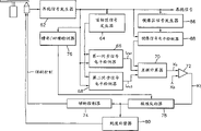
图6是表示本发明用于检测伺服误差的设备实施例的结构;Fig. 6 shows the structure of an embodiment of the apparatus for detecting servo errors according to the present invention;
图7A到7E示出图6所示设备工作期间的波形;Figures 7A to 7E show waveforms during operation of the device shown in Figure 6;
图8是表示本发明用于检测伺服误差的设备的另一实施例的结构方框图;Fig. 8 is a structural block diagram showing another embodiment of the apparatus for detecting servo errors of the present invention;
图9A到9B示出图8所示设备工作期间的波形;Figures 9A to 9B show waveforms during operation of the device shown in Figure 8;
图10示出用于校正倾斜的常规技术;Figure 10 shows a conventional technique for correcting tilt;
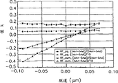
图11是表示本发明方法和设备中径向倾斜与差额值K之间关系的示图;以及Fig. 11 is a diagram showing the relationship between the radial tilt and the balance value K in the method and apparatus of the present invention; and
图12是表示本发明方法和设备中脱道(detrack)与差额值K之间关系的示图。Fig. 12 is a graph showing the relationship between detrack and the difference value K in the method and apparatus of the present invention.
具体实施方式Detailed ways
下面参照附图详细描述本发明的结构和操作。The structure and operation of the present invention will be described in detail below with reference to the accompanying drawings.
例如,在推挽信号中,取决于光盘,信号PID1与PID2的幅度与信号PID3与PID4的幅度之比变化达30%。当这种信号用作控制伺服机构的参考信号时,精确地管理伺服机构和保持最佳记录/再现状态是困难的。For example, in a push-pull signal, the ratio of the amplitudes of the signals PID1 and PID2 to the amplitudes of the signals PID3 and PID4 varies by up to 30% depending on the disc. When such a signal is used as a reference signal for controlling the servo, it is difficult to precisely manage the servo and maintain an optimum recording/reproducing state.
在本发明用于检测伺服误差的方法中,通过规则地记录在盘上的参考图案的幅度与相应于参考图案的再现信号的幅度之比检测伺服误差。参考图案可包括记录在首标区的同步信号和按盘的轨道方向记录的摆动信号。In the method for detecting a servo error of the present invention, the servo error is detected by the ratio of the amplitude of a reference pattern regularly recorded on a disc to the amplitude of a reproduced signal corresponding to the reference pattern. The reference pattern may include a sync signal recorded in the header area and a wobble signal recorded in a track direction of the disc.
首先,描述利用记录在首标区的同步信号检测伺服误差的方法。当激光斑点的光轴垂直于首标区时,即,当径向的倾斜不发生时,所检测vfo1信号的幅度(lvfo1)近似等于vfo3信号的幅度(lvfo3)。然而,在倾斜或脱道发生的情况下,当lvfo1或lvfo3变大时,其他幅度变小。First, a method of detecting a servo error using a sync signal recorded in a header area will be described. When the optical axis of the laser spot is perpendicular to the header area, ie when radial tilting does not occur, the amplitude of the detected vfo1 signal (lvfo1) is approximately equal to the amplitude of the vfo3 signal (lvfo3). However, in cases where tilting or detachment occurs, when lvfo1 or lvfo3 become larger, the other amplitudes become smaller.
这是因为从以相反方向偏离光道中心设置的PID1和PID2及PID3和PID4反射的光的强度相关于盘的倾斜变化,尽管光点跟踪光道中心。当盘向内侧倾斜时,从上部首标(顶部首标)反射的光的强度大于从下部(底部)反射的光的强度,如图1A到图2A所示。This is because the intensity of light reflected from PID1 and PID2, and PID3 and PID4, which are disposed off the track center in opposite directions, varies with respect to the tilt of the disc, although the light spot traces the track center. When the disk is tilted inward, the intensity of light reflected from the upper header (top header) is greater than that of light reflected from the lower portion (bottom), as shown in FIGS. 1A to 2A .
因此,vfo1信号的幅度lvfo1与vfo3信号的幅度lvfo3之比改变。此外,vfo2信号的幅度lvfo2与vfo4信号的幅度lvfo4之比改变,Consequently, the ratio of the amplitude lvfo1 of the vfo1 signal to the amplitude lvfo3 of the vfo3 signal changes. Furthermore, the ratio of the amplitude lvfo2 of the vfo2 signal to the amplitude lvfo4 of the vfo4 signal changes,
为了检测幅度比变化的程度,应使用以均匀电平记录的信号。由于vfo信号具有一致的电平和频率,vfo信号适用于该目的。此外,检测vfo1和vfo3信号的幅度比vfo2和vfo4信号的容易。To detect the extent of amplitude ratio variation, a signal recorded at a uniform level should be used. Since the vfo signal has a consistent level and frequency, the vfo signal is suitable for this purpose. Furthermore, it is easier to detect the magnitude of the vfo1 and vfo3 signals than the vfo2 and vfo4 signals.
这里,当在vfo1和vfo3区域检测的同步信号的幅度为lvfo1和lvfo3时,差额值K定义如下。Here, when the magnitudes of the synchronization signals detected in the vfo1 and vfo3 regions are lvfo1 and lvfo3, the difference value K is defined as follows.
K=(lvfo1-lvfo3)/(lvfo1+lvfo3) ...(1)K=(lvfo 1 -lvfo 3 )/(lvfo 1 +lvfo 3 ) ... (1)
或者or
K=(lvfo1-lvfo3)/lo ...(2)K=(lvfo 1 -lvfo 3 )/lo...(2)
其中,lo是镜像区中和信号RF_sum的幅度。Wherein, lo is the magnitude of the sum signal RF_sum in the mirror region.
在方程1和2中,利用从区域vfo1和vfo3检测的同步信号的幅度计算差额值。虽然能够利用从区域vfo2和vfo4检测的同步信号的幅度计算差额值时,检测来自区域vfo1和vfo3的同步信号比来自区域vfo2和vfo4的同步信号容易。此外,能够利用通过组合在区域vfo1和vfo2检测的同步信号获得的值和通过组合在区域vfo3和vfo4检测的同步信号获得的值。In
当在无伺服误差的情况下获得的差值K为K0,以及在存在伺服误差的情况下获得的差额值K为K1时,两值之间的差定义如下。When the difference K obtained in the absence of a servo error is K 0 , and the difference K obtained in the presence of a servo error is K 1 , the difference between the two values is defined as follows.
Kt=K0-K1 ...(3)K t =K 0 -K 1 ...(3)
即,根据Kt的值和符号能够知道伺服误差的方向和幅度。That is, the direction and magnitude of the servo error can be known from the value and sign of Kt .
在此,K0可以是在无伺服误差的状态下测量的值,记录/再现装置的系统控制器确定的缺省值,或者在由系统确定的参考状态下测量的值。Here, K 0 may be a value measured in a state of no servo error, a default value determined by the system controller of the recording/reproducing apparatus, or a value measured in a reference state determined by the system.
在槽脊光道和凹槽光道中,K1的极性应改变以正确地计算Kt,因为PID1和PID2的位置与PID3和PID4的位置相反。In land and groove tracks, the polarity of K1 should be changed to calculate Kt correctly because the positions of PID1 and PID2 are opposite to those of PID3 and PID4.
现在描述利用摆动信号检测盘的伺服误差的方法。在DVD-RAM光盘的槽脊光道和凹槽光道中形成摆动。摆动为形成在光道的侧壁上的正弦波形式。A method of detecting a servo error of a disc using a wobble signal will now be described. Wobbles are formed in the land and groove tracks of DVD-RAM discs. The wobbles are in the form of sinusoidal waves formed on the sidewalls of the track.
当光盘在径向倾斜时,摆动信号径向倾斜。即,摆动信号的幅度在径向的两个任意彼此相互分离的点之间变化。因此,能够通过检测径向摆动信号的变化量来检测倾斜。When the disc is tilted radially, the wobble signal is tilted radially. That is, the amplitude of the wobble signal varies between two arbitrary points separated from each other in the radial direction. Therefore, it is possible to detect tilt by detecting the change amount of the radial wobble signal.
图6是表示本发明用于检测伺服误差的设备实施例的结构方框图。图6所示的设备包括再现信号发生器62,首标区检测器64,第一同步信号电平检测器66,第二同步信号电平检测器68,差额计算器70,比较器72,槽脊/凹槽检测器76,倾斜控制器74,极性反相器78,以及脱道补偿器80。Fig. 6 is a block diagram showing the structure of an embodiment of the apparatus for detecting servo errors of the present invention. The apparatus shown in FIG. 6 includes a reproduced
再现信号发生器62产生和信号RF_sum,径向对的和信号V1和V2,以及将V1与V2相减获得的推挽信号RF_pp。再现信号发生器62包括一分为四的光检测器和计算器,如图5所示。The
首标区检测器64从再现信号产生首标区信号(首标区信号1和首标区信号2),表示首标区。这这里,首标区信号1通知PID1和PID2区域。首标区信号2通知PID3和PID4区域。由于首标区具有大于数据区的包络,能够利用检测再现信号包络的包络检测器和比较器获得表示首标区的首标区信号。The
与首标区检测器64产生的首标区信号1同步的第一同步信号电平检测器66检测图4所示的vfo1信号的幅度lvfo1。具体地说,产生具有预定宽度并与首标区信号1的起始点分开预定距离的第一启动信号(启动1)。在用第一启动信号(启动1)选通再现信号之后,通过检测再现信号的峰-峰值检测vfo1信号的幅度lvfo1。The first synchronizing
与首标区检测器64产生的首标区信号2同步的第二同步信号电平检测器68检测图4所示的vfo3信号的幅度。具体地说,通过产生具有预定宽度并与首标区信号2分离的第二启动信号(启动2)、用第二启动信号(启动2)选通再现信号、并检测选通再现信号的峰-峰值,检测vfo3信号的幅度lvfo3。A second synchronous
差额计算器70计算第一同步信号电平检测器66检测的vfo1信号的幅度lvfo1与第二同步信号电平检测器68检测的vfo3信号的幅度lvfo3之比,如方程1所示。此处,差额计算器70可输出在径向或正切方向从若干连续扇区获得的差额值的平均值。The
比较器72比较差额计算器70计算的差额值K1与预定参考值K0,并输出两个值Kt之间的差,如方程3所示。此处,K0可以是在没有倾斜的状态下测量的值,记录/再现设备的系统控制器确定的缺省值,或在系统确定的参考状态下测量的值。The
槽脊/凹槽检测器76接收再现信号并检测当前光道是槽脊光道还是凹槽光道。在槽脊光道的推挽信号中,PID1和PID2的幅度小于图1B所示PID3和PID4的幅度。在凹槽光道的推挽信号中,PID1和PID2的幅度小于PID3和PID4的幅度。槽脊/凹槽检测器76利用以上所述鉴别槽脊光道与凹槽光道。The land/
极性反相器78根据槽脊/凹槽检测器76检测的结果反相从比较器72输出的减法值Kt的极性。The
为了补偿倾斜可采用差额值。To compensate for tilting, a difference value can be used.
倾斜控制器74根据减法值Kt控制盘的倾斜,减法值Kt的极性反相并从极性反相器78输出。由于减法值Kt的符号与幅度表示倾斜的方向和幅度,通过反馈减法值Kt的符号和幅度控制盘的倾斜。The tilt
为了校正脱道可以采用差额值。To correct for runaways, a difference value can be used.
脱道补偿器80根据减法值Kt控制盘的脱道,减法值Kt的极性反相并从极性反相器78输出。由于减法值Kt的符号与幅度表示倾斜的方向和幅度,通过反馈减法值Kt的符号和幅度控制盘的脱道。The off-
图7示出图6所示设备的工作波形。图7A示出再现信号发生器62产生的推挽信号波形。图7B和7C分别示出首标区信号发生器产生的首标区信号1和首标区信号2的波形。图7D和7E示出第一同步信号电平检测器66和第二同步信号电平检测器68利用的第一启动信号(启动1)和第二启动信号(启动2)的波形。FIG. 7 shows operating waveforms of the device shown in FIG. 6 . FIG. 7A shows a push-pull signal waveform generated by the reproduced
图8是表示本发明用于检测伺服误差的设备的另一实施例的结构方框图。图8所示设备除了包括镜像区信号发生器86和镜像信号电平检测器88以外与图6所示设备类似。因此,用相同标号表示相同部件并省略其详细描述。Fig. 8 is a block diagram showing the structure of another embodiment of the apparatus for detecting servo errors of the present invention. The apparatus shown in FIG. 8 is similar to the apparatus shown in FIG. 6 except that it includes a mirror
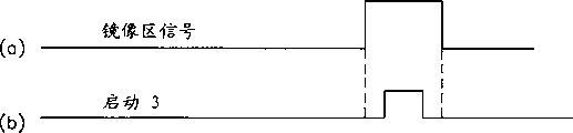
镜像区信号发生器86产生表示来自再现信号发生器62提供的和信号RF_sum的镜像区的镜像区信号。在推挽信号RF_pp中,由于镜像信号变为0,能够用推挽信号RF_pp获得镜像区信号。The mirror
由于镜像信号具有远低于数据区和首标区信号的包络低得多的包络,能够用包络检测器和比较器产生镜像区信号。Since the mirror signal has a much lower envelope than the data field and header field signals, an envelope detector and a comparator can be used to generate the mirror field signal.
镜像信号电平检测器88用镜像区信号发生器86产生的镜像区信号从和信号RF_sum检测镜像信号电平。镜像信号电平检测器88由镜像区信号发生器产生的镜像区信号产生具有预定周期的第三启动信号(启动3),用第三启动信号(启动3)选通和信号RF_sum,及检测选通的和信号RF_sum的峰-峰值。The mirror
差额计算器72用第一同步信号电平检测器66检测的vfo1信号的电平lvfo1、第二同步信号电平检测器68检测的vfo3信号的电平lvfo3、及镜像信号电平检测器88检测的镜像信号电平lo如方程2所示计算差额值K1。这里,差额计算器72可输出在径向和正切方向获得的若干连续扇区的差额值的平均值。The
图9A和9B示出图8所示设备工作期间的波形。图9A示出从镜像区信号发生器86输出的镜像区信号的波形。图9B示出第三启动信号(启动3)的波形。9A and 9B show waveforms during operation of the device shown in FIG. 8 . FIG. 9A shows the waveform of the mirror area signal output from the mirror
按照本发明,能够利用推挽信号RF_pp、径向对的和信号V1和V2、及用于检测伺服误差的和信号RF_sum,因为用同步信号的差额值检测伺服误差。例如,当利用推挽信号RF_pp时,能够补偿径向的倾斜。当利用和信号RF_sum时,能够补偿正切方向的倾斜。According to the invention, it is possible to use the push-pull signal RF_pp, the sum signals V1 and V2 of the radial pairs, and the sum signal RF_sum for detecting the servo error, since the servo error is detected with the difference value of the synchronization signal. For example, when using the push-pull signal RF_pp, the radial tilt can be compensated. When using the sum signal RF_sum, the tilt in the tangential direction can be compensated.
图11示出本发明的方法和设备中径向倾斜与差额值K之间的关系。在图11中,水平轴表示径向倾斜值,垂直轴表示差额值K。在图11中,用·标记的曲线表示利用按照方程1的和信号RF_sum与差额值的情况。用◆标记的曲线表示利用按照方程2的和信号RF_sum与差额值的情况。用●标记的曲线表示利用按照方程2的推挽信号RF_pp与差额值的情况。用■标记的曲线表示利用按照方程1的推挽信号RF_pp与差额值的情况。Figure 11 shows the relationship between the radial tilt and the difference value K in the method and apparatus of the present invention. In FIG. 11, the horizontal axis represents the radial inclination value, and the vertical axis represents the difference value K. In FIG. 11, the curve marked with · represents the case of using the sum signal RF_sum according to Eq. 1 and the difference value. The curve marked with ♦ represents the case of using the sum signal RF_sum according to Eq. 2 and the difference value. The curve marked with - represents the case with the push-pull signal RF_pp according to Equation 2 and the difference value. The curve marked with ■ represents the case with the push-pull signal RF_pp according to
如图11所示,用■标记利用按照方程1的推挽信号RF_pp与差额值的情况最佳地描述了径向倾斜。用●标记的利用按照方程2的推挽信号RF_pp与差额值的情况也有益于描述径向倾斜。As shown in FIG. 11 , the case with the push-pull signal RF_pp and the difference value according to
因此,能够利用推挽信号RF_pp用根据方程1和2的值确定倾斜。Thus, the tilt can be determined with values according to
图12是表示本发明方法和设备中脱道与差额值K之间关系的示图。在图12中,水平轴表示脱道量。垂直轴表示差额值K。在图12中,用·标记的曲线表示利用按照方程1的和信号RF_sum与差额值的情况。用◆标记的曲线表示利用按照方程2的和信号RF_sum与差额值的情况。用●标记的曲线表示利用按照方程2的推挽信号RF_pp与差额值的情况。用■标记的曲线表示利用按照方程1的推挽信号RF_pp与差额值的情况。Fig. 12 is a graph showing the relationship between off-track and the balance value K in the method and apparatus of the present invention. In FIG. 12 , the horizontal axis represents the amount of slippage. The vertical axis represents the difference value K. In FIG. 12, the curve marked with · represents the case of using the sum signal RF_sum according to Eq. 1 and the difference value. The curve marked with ♦ represents the case of using the sum signal RF_sum according to Eq. 2 and the difference value. The curve marked with - represents the case with the push-pull signal RF_pp according to Equation 2 and the difference value. The curve marked with ■ represents the case with the push-pull signal RF_pp according to
如图12所示,用·标记的曲线表示按照方程1的和信号RF_sum与差额值受脱道影响最大的情况。用■标记的曲线按照方程1的推挽信号RF_pp与差额值受脱道影响最小的情况。As shown in FIG. 12 , the curve marked with · represents the case where the sum signal RF_sum and the difference value according to
因此能够利用和信号RF_sum用按照方程1或2的值确定脱道。The value according to
如图11和12所示,当利用按照方程1的推挽信号RF_pp和差额值时,能够最有效地检测倾斜量。As shown in FIGS. 11 and 12 , when using the push-pull signal RF_pp and the difference value according to
伺服误差信号的质量根据盘的质量和系统的条件改变。然而,当伺服误差信号的值某种程度上不受限制时,不可能识别PID或者稳定地管理伺服机构是困难的。因此,在盘中,最好管理值K0保持于规定电平。The quality of the servo error signal varies depending on the quality of the disc and the conditions of the system. However, when the value of the servo error signal is somewhat unlimited, it is impossible to identify the PID or it is difficult to manage the servo mechanism stably. Therefore, in the disc, it is preferable to keep the management value K 0 at a predetermined level.
因此,在本发明中,建议值K0限制为±0.1。当给定倾斜±0.35°的标准量时需要该值来正常再现PID。此外,考虑光道控制的容许范围。Therefore, in the present invention, the suggested value K 0 is limited to ±0.1. This value is required to properly reproduce the PID given the standard amount of tilt ±0.35°. In addition, consider the allowable range of track control.
此外,有必要限制值Kt不大于预定值,以精确地控制用于从盘再现数据的设备的伺服机构。当再现数据时不对伺服机构的质量进行严格的管理时。不能够获得PID信息。Furthermore, it is necessary to limit the value K t not to be greater than a predetermined value in order to accurately control the servo mechanism of the apparatus for reproducing data from the disc. When the quality of the servo mechanism is not strictly managed when reproducing data. Unable to obtain PID information.
因此,在本发明中,建议在再现设备的伺服操作中将值Kt限制为±0.1。Therefore, in the present invention, it is proposed to limit the value K t to ±0.1 in the servo operation of the reproducing device.
利用本发明检测伺服误差的方法能够正确地检测盘的倾斜,而无需检测伺服误差的特定图案。The method of detecting servo errors using the present invention can correctly detect the tilt of the disc without detecting a specific pattern of servo errors.
记录/再现设备能够稳定地控制伺服并保持最佳记录/再现状态,因为本发明用于产生伺服误差的设备正确地检测盘的伺服误差状态。The recording/reproducing apparatus can stably control the servo and maintain the optimum recording/reproducing state because the apparatus for generating servo error of the present invention correctly detects the servo error state of the disc.
由于能够严格地管理作为用本发明的盘控制伺服的基础的伺服误差信号电平,记录/再现设备能够稳定地控制伺服并保持最佳记录/再现状态。Since the level of the servo error signal which is the basis for servo control with the disc of the present invention can be strictly managed, the recording/reproducing apparatus can stably control the servo and maintain an optimum recording/reproducing state.
Claims (35)
Applications Claiming Priority (9)
| Application Number | Priority Date | Filing Date | Title |
|---|---|---|---|
| KR35421/1998 | 1998-08-29 | ||
| KR35421/98 | 1998-08-29 | ||
| KR35422/98 | 1998-08-29 | ||
| KR19980035422 | 1998-08-29 | ||
| KR19980035421 | 1998-08-29 | ||
| KR35422/1998 | 1998-08-29 | ||
| KR8482/99 | 1999-03-13 | ||
| KR1019990008482A KR100618962B1 (en) | 1998-08-29 | 1999-03-13 | Servo error detection method, suitable device, tracking error detection method, and tilt error detection method |
| KR8482/1999 | 1999-03-13 |
Related Child Applications (3)
| Application Number | Title | Priority Date | Filing Date |
|---|---|---|---|
| CNB011046651A Division CN1236428C (en) | 1998-08-29 | 1999-08-30 | Optical disk, optical disk servo error control method and its device |
| CNB011046635A Division CN1236430C (en) | 1998-08-29 | 1999-08-30 | Detection method for optical disk bank error and its device |
| CNB011046643A Division CN1236433C (en) | 1998-08-29 | 1999-08-30 | Optical disk servo error detection method and its device |
Publications (2)
| Publication Number | Publication Date |
|---|---|
| CN1246703A CN1246703A (en) | 2000-03-08 |
| CN1246845C true CN1246845C (en) | 2006-03-22 |
Family
ID=38169480
Family Applications (4)
| Application Number | Title | Priority Date | Filing Date |
|---|---|---|---|
| CNB991184017A Expired - Lifetime CN1246845C (en) | 1998-08-29 | 1999-08-30 | Servo error detection method and device and method for detecting tracking error |
| CNB011046651A Expired - Lifetime CN1236428C (en) | 1998-08-29 | 1999-08-30 | Optical disk, optical disk servo error control method and its device |
| CNB011046643A Expired - Lifetime CN1236433C (en) | 1998-08-29 | 1999-08-30 | Optical disk servo error detection method and its device |
| CNB011046635A Expired - Lifetime CN1236430C (en) | 1998-08-29 | 1999-08-30 | Detection method for optical disk bank error and its device |
Family Applications After (3)
| Application Number | Title | Priority Date | Filing Date |
|---|---|---|---|
| CNB011046651A Expired - Lifetime CN1236428C (en) | 1998-08-29 | 1999-08-30 | Optical disk, optical disk servo error control method and its device |
| CNB011046643A Expired - Lifetime CN1236433C (en) | 1998-08-29 | 1999-08-30 | Optical disk servo error detection method and its device |
| CNB011046635A Expired - Lifetime CN1236430C (en) | 1998-08-29 | 1999-08-30 | Detection method for optical disk bank error and its device |
Country Status (11)
| Country | Link |
|---|---|
| US (8) | US6469979B1 (en) |
| EP (4) | EP1308941A1 (en) |
| JP (9) | JP2000076681A (en) |
| KR (1) | KR100618962B1 (en) |
| CN (4) | CN1246845C (en) |
| BR (3) | BR9917653B1 (en) |
| DE (2) | DE69937132T2 (en) |
| ID (1) | ID23764A (en) |
| MY (2) | MY122541A (en) |
| SG (3) | SG134978A1 (en) |
| TW (1) | TW451184B (en) |
Families Citing this family (37)
| Publication number | Priority date | Publication date | Assignee | Title |
|---|---|---|---|---|
| JP2856391B2 (en) * | 1996-05-30 | 1999-02-10 | 株式会社日立製作所 | Information recording method and information recording device |
| KR100618962B1 (en) * | 1998-08-29 | 2006-09-01 | 삼성전자주식회사 | Servo error detection method, suitable device, tracking error detection method, and tilt error detection method |
| EP0987691B1 (en) * | 1998-09-14 | 2000-10-04 | Matsushita Electric Industrial Co., Ltd. | Tilt detection device, optical disc recording and reproducing device, and tilt detection method |
| KR100565043B1 (en) * | 1998-09-15 | 2006-03-30 | 삼성전자주식회사 | Tilt and de-track detection devices, tilt and de-track controls, suitable reference method setting and discs suitable |
| KR100577151B1 (en) * | 1999-04-16 | 2006-05-09 | 엘지전자 주식회사 | Method and apparatus for recording and reproducing optical recording media |
| JP2000298857A (en) * | 1999-03-30 | 2000-10-24 | Lg Electronics Inc | Optical recording medium recording / reproducing method and apparatus |
| US7085204B1 (en) * | 1999-05-18 | 2006-08-01 | Lg Electronics, Inc. | Method and apparatus for controlling record and reproduction of optical record medium involving averaging servo error signals |
| KR100346701B1 (en) * | 1999-05-25 | 2002-08-01 | 삼성전자 주식회사 | Output control method of laser diode and apparatus thereof |
| DE19934473A1 (en) * | 1999-07-27 | 2001-02-01 | Thomson Brandt Gmbh | Device for writing on optical recording media |
| JP3817408B2 (en) * | 2000-03-28 | 2006-09-06 | 三星電機株式会社 | Tilt detection device |
| TW501113B (en) * | 2000-04-25 | 2002-09-01 | Samsung Electronics Co Ltd | Optical disc |
| US7369968B2 (en) * | 2000-06-16 | 2008-05-06 | Verisae, Inc. | Enterprise energy management system |
| JP2002008246A (en) * | 2000-06-20 | 2002-01-11 | Sony Corp | Disc-shaped recording medium, disc recording and / or reproducing apparatus and method, and tilt detecting method |
| KR100379399B1 (en) * | 2000-10-02 | 2003-04-10 | 엘지전자 주식회사 | Method and apparatus for detecting header area of optical record medium and method for recording/playing using the same |
| KR100375223B1 (en) * | 2000-11-21 | 2003-03-07 | 엘지전자 주식회사 | Apparatus for optical pick-up and methode for tilt controlling of optical pick-up |
| JP3674565B2 (en) * | 2001-09-25 | 2005-07-20 | ティアック株式会社 | Optical disk device |
| US7899862B2 (en) | 2002-11-18 | 2011-03-01 | Aol Inc. | Dynamic identification of other users to an online user |
| JP2004327007A (en) | 2003-04-08 | 2004-11-18 | Nec Corp | Optical information recording medium and reproducing device |
| JP2004362672A (en) * | 2003-06-04 | 2004-12-24 | Sanyo Electric Co Ltd | Tilt control method of optical disk reproducing device |
| US6958881B1 (en) | 2003-11-26 | 2005-10-25 | Western Digital Technologies, Inc. | Disk drive control system having a servo processing accelerator circuit |
| KR20050052606A (en) * | 2003-11-28 | 2005-06-03 | 삼성전자주식회사 | Information storage medium, method and apparatus for reproducing of information recorded in the same |
| US20060153048A1 (en) * | 2003-12-01 | 2006-07-13 | Kuo-Jung Lan | Protection window signal generator for header detection and method thereof |
| TWI230930B (en) * | 2003-12-01 | 2005-04-11 | Mediatek Inc | Protecting method and related apparatus for accurate header detection |
| TWI260013B (en) * | 2003-12-04 | 2006-08-11 | Mediatek Inc | Optical incidence auto-adjusting system |
| US7133235B2 (en) * | 2004-02-25 | 2006-11-07 | Hitachi Global Storage Technologies Netherlands, B.V. | System and method for correcting for head tilt in HDD |
| TWI288397B (en) | 2004-05-12 | 2007-10-11 | Mediatek Inc | Method and related apparatus for dynamically adjust a RF gain while accessing a DVD-RAM optical disc |
| US20070133365A1 (en) * | 2005-12-12 | 2007-06-14 | Shih-Hao Ko | Tilt calibration apparatus and method capable of adjusting included angle between optical pick-up head and optical disc according to wobble signal |
| TW200741654A (en) * | 2006-03-03 | 2007-11-01 | Mediatek Inc | Protection window signal generator for header detection and method thereof |
| US7796480B2 (en) * | 2006-06-05 | 2010-09-14 | Mediatek Inc. | Apparatus and methods for light spot servo signal detection |
| US7684291B2 (en) * | 2006-06-05 | 2010-03-23 | Mediatek Inc. | Method and apparatus for blank detection of an optical disc |
| TW200810358A (en) * | 2006-06-05 | 2008-02-16 | Mediatek Inc | Apparatus and method of detecting a target peak value and a target bottom value of an input signal |
| US20070280079A1 (en) * | 2006-06-05 | 2007-12-06 | Yuh Cheng | Asymmetry measurement apparatus |
| US7724090B2 (en) * | 2006-06-05 | 2010-05-25 | Mediatek Inc. | Loop control apparatus and method thereof |
| TWI332658B (en) * | 2006-06-14 | 2010-11-01 | Realtek Semiconductor Corp | Tilt error detecting apparatus, tilt calibration apparatus, tilt error detecting method and tilt calibration method |
| TW201142838A (en) * | 2010-05-25 | 2011-12-01 | Quanta Storage Inc | Method for detecting obliquity of optical disk drive |
| TW201225075A (en) * | 2010-12-02 | 2012-06-16 | Quanta Storage Inc | Method for detecting obliquity of optical disc drive |
| US11175466B2 (en) | 2015-07-02 | 2021-11-16 | Senko Advanced Components, Inc. | Bayonet lock MPO connector |
Family Cites Families (34)
| Publication number | Priority date | Publication date | Assignee | Title |
|---|---|---|---|---|
| JPS58125242A (en) * | 1982-01-22 | 1983-07-26 | Victor Co Of Japan Ltd | Tracking error detecting system of optical information signal reproducing device |
| JPH0680535B2 (en) | 1982-08-27 | 1994-10-12 | 株式会社日立製作所 | Information recording / playback method |
| JPS60195745A (en) * | 1984-03-16 | 1985-10-04 | Pioneer Electronic Corp | Tracking servo signal producing system |
| US4748609A (en) * | 1985-03-29 | 1988-05-31 | Hitachi, Ltd. | Method and apparatus for composite tracking servo system with track offset correction and rotary optical disc having at least one correction mark for correcting track offset |
| JP2599418B2 (en) | 1988-03-14 | 1997-04-09 | 松下通信工業株式会社 | Tracking servo device |
| JP2893752B2 (en) * | 1989-09-29 | 1999-05-24 | ソニー株式会社 | Disk-shaped recording medium |
| JP2998807B2 (en) * | 1990-07-19 | 2000-01-17 | パイオニア株式会社 | Optical disc player |
| JP2866160B2 (en) | 1990-07-19 | 1999-03-08 | パイオニア株式会社 | Optical disc player |
| US5327408A (en) * | 1990-09-07 | 1994-07-05 | International Business Machines Corporation | Optical disk with sector servo patterns compensating for variations in pattern size and/or radial velocity |
| DE4028703A1 (en) * | 1990-09-10 | 1992-03-12 | Thomson Brandt Gmbh | METHOD FOR MEASURING OR CONTROLLING THE RADIAL AND TANGENTIAL ANGLE OF A LIGHT BEAM |
| US5257149A (en) * | 1991-02-13 | 1993-10-26 | Seagate Technology, Inc. | Disc drive with offset address field |
| JPH05144024A (en) | 1991-11-19 | 1993-06-11 | Konica Corp | Servo mechanism for optical disk device |
| US5815485A (en) * | 1993-02-02 | 1998-09-29 | Matsushita Electric Industrial Co., Ltd. | Recording medium, a method for producing the same, a control method using the recording medium, and a recording/reproducing apparatus using the recording medium |
| JP3161891B2 (en) * | 1993-11-16 | 2001-04-25 | 松下電器産業株式会社 | Disc tilt detecting device and disc tilt correcting device |
| JPH07220280A (en) * | 1994-01-26 | 1995-08-18 | Pioneer Electron Corp | Calibration method and apparatus in write-once optical disc recording apparatus |
| US5751512A (en) * | 1994-01-28 | 1998-05-12 | Seagate Technology, Inc. | Data storage format for data storage devices having a radial offset between read and write elements |
| US5587850A (en) * | 1994-08-26 | 1996-12-24 | Quantum Corporation | Data track pattern including embedded servo sectors for magneto-resistive read/inductive write head structure for a disk drive |
| JP3025472B2 (en) | 1995-02-17 | 2000-03-27 | 松下電器産業株式会社 | Optical disk recording / reproducing device |
| US5732054A (en) * | 1995-03-28 | 1998-03-24 | Eastman Kodak Company | Combined tracking position and tilt sensor for optical recording actuator |
| US6324030B1 (en) * | 1995-05-02 | 2001-11-27 | International Business Machines Corporation | Digital pes demodulation for a disk drive servo control system using synchronous digital sampling |
| JP3232966B2 (en) | 1995-08-22 | 2001-11-26 | 松下電器産業株式会社 | Tracking control device for optical disk recording / reproducing device |
| JP3063598B2 (en) * | 1995-12-01 | 2000-07-12 | 三菱電機株式会社 | Optical disk and optical disk device |
| JPH09251639A (en) | 1996-01-11 | 1997-09-22 | So Fukada | Optical disc and recording / reproducing apparatus thereof |
| JPH09259576A (en) | 1996-03-25 | 1997-10-03 | Toshiba Corp | Information recording disc with multiple management areas |
| US6215758B1 (en) * | 1996-10-04 | 2001-04-10 | Sony Corporation | Recording medium |
| JP3103505B2 (en) * | 1996-06-26 | 2000-10-30 | 三菱電機株式会社 | Optical disk and optical disk drive |
| JPH1027366A (en) | 1996-07-15 | 1998-01-27 | Matsushita Electric Ind Co Ltd | Optical disk drive method and optical disk drive |
| US5986592A (en) * | 1996-10-01 | 1999-11-16 | Sony Corporation | Encoder decoder device not using an A/D converter and method thereof |
| JPH10275335A (en) * | 1997-04-01 | 1998-10-13 | Toshiba Corp | Information recording / reproducing optical disc and method for forming information recording / reproducing optical disc |
| JP3104222B2 (en) * | 1997-05-19 | 2000-10-30 | ソニー株式会社 | Optical disk drive |
| KR100244772B1 (en) * | 1997-07-26 | 2000-02-15 | 전주범 | Tracking servo of digital video disc rewrite system |
| KR100277023B1 (en) * | 1997-08-30 | 2001-01-15 | 구자홍 | Tracking Servo |
| KR100618962B1 (en) | 1998-08-29 | 2006-09-01 | 삼성전자주식회사 | Servo error detection method, suitable device, tracking error detection method, and tilt error detection method |
| JP2000287493A (en) * | 1999-03-30 | 2000-10-13 | Matsushita Electric Ind Co Ltd | Motor protection device |
-
1999
- 1999-03-13 KR KR1019990008482A patent/KR100618962B1/en not_active Expired - Lifetime
- 1999-08-26 SG SG200207752-7A patent/SG134978A1/en unknown
- 1999-08-26 SG SG9904192A patent/SG115328A1/en unknown
- 1999-08-26 SG SG200207792-3A patent/SG134979A1/en unknown
- 1999-08-26 JP JP11240545A patent/JP2000076681A/en not_active Withdrawn
- 1999-08-27 TW TW088114772A patent/TW451184B/en not_active IP Right Cessation
- 1999-08-27 DE DE69937132T patent/DE69937132T2/en not_active Expired - Lifetime
- 1999-08-27 EP EP02025798A patent/EP1308941A1/en not_active Withdrawn
- 1999-08-27 MY MYPI20023217A patent/MY122541A/en unknown
- 1999-08-27 DE DE69936598T patent/DE69936598T2/en not_active Expired - Lifetime
- 1999-08-27 EP EP02025433A patent/EP1293972A3/en not_active Withdrawn
- 1999-08-27 MY MYPI99003713A patent/MY122151A/en unknown
- 1999-08-27 EP EP02025372A patent/EP1308940B1/en not_active Expired - Lifetime
- 1999-08-27 EP EP99306812A patent/EP0984436B1/en not_active Expired - Lifetime
- 1999-08-30 CN CNB991184017A patent/CN1246845C/en not_active Expired - Lifetime
- 1999-08-30 BR BRPI9917653-0A patent/BR9917653B1/en not_active IP Right Cessation
- 1999-08-30 BR BRPI9917654-8A patent/BR9917654B1/en not_active IP Right Cessation
- 1999-08-30 US US09/385,415 patent/US6469979B1/en not_active Expired - Lifetime
- 1999-08-30 CN CNB011046651A patent/CN1236428C/en not_active Expired - Lifetime
- 1999-08-30 BR BR9903978-8A patent/BR9903978A/en not_active Application Discontinuation
- 1999-08-30 CN CNB011046643A patent/CN1236433C/en not_active Expired - Lifetime
- 1999-08-30 CN CNB011046635A patent/CN1236430C/en not_active Expired - Lifetime
- 1999-08-30 ID IDP990824D patent/ID23764A/en unknown
-
2000
- 2000-07-31 US US09/629,049 patent/US6556520B1/en not_active Expired - Lifetime
- 2000-07-31 US US09/629,050 patent/US6556521B1/en not_active Expired - Lifetime
- 2000-10-20 JP JP2000321768A patent/JP2001155361A/en active Pending
-
2001
- 2001-07-16 JP JP2001215864A patent/JP2002083437A/en active Pending
- 2001-07-16 JP JP2001215863A patent/JP2002109752A/en active Pending
- 2001-07-16 JP JP2001215866A patent/JP2002074715A/en active Pending
- 2001-07-16 JP JP2001215865A patent/JP4527321B2/en not_active Expired - Lifetime
-
2002
- 2002-07-08 JP JP2002199239A patent/JP2003030880A/en active Pending
- 2002-07-08 JP JP2002199240A patent/JP2003067957A/en active Pending
-
2003
- 2003-03-05 US US10/378,904 patent/US6721243B2/en not_active Expired - Lifetime
- 2003-03-12 US US10/385,472 patent/US7167424B2/en not_active Expired - Lifetime
-
2004
- 2004-05-20 JP JP2004150990A patent/JP2004265593A/en active Pending
-
2005
- 2005-04-01 US US11/095,481 patent/US7110334B2/en not_active Expired - Lifetime
- 2005-12-16 US US11/304,636 patent/US7319643B2/en not_active Expired - Lifetime
-
2007
- 2007-11-26 US US11/944,863 patent/US7590034B2/en not_active Expired - Fee Related
Also Published As
Similar Documents
| Publication | Publication Date | Title |
|---|---|---|
| CN1236433C (en) | Optical disk servo error detection method and its device | |
| CN1167972A (en) | Optical information recording/reproducing device and method for recording/reproducing information | |
| HK1037775B (en) | Method for detecting incline error of optical disk | |
| HK1037777B (en) | Method for detecting incline error of device for reproducing data in optical disk | |
| HK1037776B (en) | Device for detecting incline error | |
| KR100354748B1 (en) | Tilt detection method of optical disc drive | |
| CN1207708C (en) | Optical disk apparatus capable of generating clock accurately | |
| KR100601727B1 (en) | Disk having pits to detect amount of servo error and detrack | |
| HK1030091A1 (en) | Disk device |
Legal Events
| Date | Code | Title | Description |
|---|---|---|---|
| C10 | Entry into substantive examination | ||
| SE01 | Entry into force of request for substantive examination | ||
| C06 | Publication | ||
| PB01 | Publication | ||
| C14 | Grant of patent or utility model | ||
| GR01 | Patent grant | ||
| EE01 | Entry into force of recordation of patent licensing contract |
Application publication date: 20000308 Assignee: China Hualu Group Ltd. Assignor: Blue light United Co., Ltd. Contract record no.: 2014990000238 Denomination of invention: Servo error detecting method and equipment, method for control disk recording/playback equipment servo Granted publication date: 20060322 License type: Common License Record date: 20140423 Application publication date: 20000308 Assignee: Guangdong OPPO Mobile Communications Co., Ltd. Assignor: Blue light United Co., Ltd. Contract record no.: 2014990000237 Denomination of invention: Servo error detecting method and equipment, method for control disk recording/playback equipment servo Granted publication date: 20060322 License type: Common License Record date: 20140423 Application publication date: 20000308 Assignee: TCL Kone Electronics (Huizhou) Ltd. Assignor: Blue light United Co., Ltd. Contract record no.: 2014990000240 Denomination of invention: Servo error detecting method and equipment, method for control disk recording/playback equipment servo Granted publication date: 20060322 License type: Common License Record date: 20140423 Application publication date: 20000308 Assignee: Guangzhou Panyu Juda Car Audio Equipment Co., Ltd. Assignor: Blue light United Co., Ltd. Contract record no.: 2014990000233 Denomination of invention: Servo error detecting method and equipment, method for control disk recording/playback equipment servo Granted publication date: 20060322 License type: Common License Record date: 20140422 Application publication date: 20000308 Assignee: Shenzhen Maxmade Technology Co.,Ltd. Assignor: Blue light United Co., Ltd. Contract record no.: 2014990000239 Denomination of invention: Servo error detecting method and equipment, method for control disk recording/playback equipment servo Granted publication date: 20060322 License type: Common License Record date: 20140423 |
|
| LICC | Enforcement, change and cancellation of record of contracts on the licence for exploitation of a patent or utility model | ||
| EE01 | Entry into force of recordation of patent licensing contract |
Application publication date: 20000308 Assignee: Dongguan de video technology Co. Ltd. Kit Assignor: Blue light United Co., Ltd. Contract record no.: 2016990000233 Denomination of invention: Servo error detecting method and equipment, method for control disk recording/playback equipment servo Granted publication date: 20060322 License type: Common License Record date: 20160614 |
|
| LICC | Enforcement, change and cancellation of record of contracts on the licence for exploitation of a patent or utility model | ||
| CX01 | Expiry of patent term |
Granted publication date: 20060322 |
|
| CX01 | Expiry of patent term |