CN1255968A - Assembly Structure of Rotational Displacement Detector - Google Patents
Assembly Structure of Rotational Displacement Detector Download PDFInfo
- Publication number
- CN1255968A CN1255968A CN98805060A CN98805060A CN1255968A CN 1255968 A CN1255968 A CN 1255968A CN 98805060 A CN98805060 A CN 98805060A CN 98805060 A CN98805060 A CN 98805060A CN 1255968 A CN1255968 A CN 1255968A
- Authority
- CN
- China
- Prior art keywords
- mentioned
- input shaft
- detecting device
- swing offset
- package assembly
- Prior art date
- Legal status (The legal status is an assumption and is not a legal conclusion. Google has not performed a legal analysis and makes no representation as to the accuracy of the status listed.)
- Granted
Links
Images







Classifications
-
- G—PHYSICS
- G01—MEASURING; TESTING
- G01D—MEASURING NOT SPECIALLY ADAPTED FOR A SPECIFIC VARIABLE; ARRANGEMENTS FOR MEASURING TWO OR MORE VARIABLES NOT COVERED IN A SINGLE OTHER SUBCLASS; TARIFF METERING APPARATUS; MEASURING OR TESTING NOT OTHERWISE PROVIDED FOR
- G01D5/00—Mechanical means for transferring the output of a sensing member; Means for converting the output of a sensing member to another variable where the form or nature of the sensing member does not constrain the means for converting; Transducers not specially adapted for a specific variable
- G01D5/12—Mechanical means for transferring the output of a sensing member; Means for converting the output of a sensing member to another variable where the form or nature of the sensing member does not constrain the means for converting; Transducers not specially adapted for a specific variable using electric or magnetic means
- G01D5/244—Mechanical means for transferring the output of a sensing member; Means for converting the output of a sensing member to another variable where the form or nature of the sensing member does not constrain the means for converting; Transducers not specially adapted for a specific variable using electric or magnetic means influencing characteristics of pulses or pulse trains; generating pulses or pulse trains
- G01D5/245—Mechanical means for transferring the output of a sensing member; Means for converting the output of a sensing member to another variable where the form or nature of the sensing member does not constrain the means for converting; Transducers not specially adapted for a specific variable using electric or magnetic means influencing characteristics of pulses or pulse trains; generating pulses or pulse trains using a variable number of pulses in a train
-
- F—MECHANICAL ENGINEERING; LIGHTING; HEATING; WEAPONS; BLASTING
- F16—ENGINEERING ELEMENTS AND UNITS; GENERAL MEASURES FOR PRODUCING AND MAINTAINING EFFECTIVE FUNCTIONING OF MACHINES OR INSTALLATIONS; THERMAL INSULATION IN GENERAL
- F16D—COUPLINGS FOR TRANSMITTING ROTATION; CLUTCHES; BRAKES
- F16D1/00—Couplings for rigidly connecting two coaxial shafts or other movable machine elements
- F16D1/10—Quick-acting couplings in which the parts are connected by simply bringing them together axially
- F16D1/101—Quick-acting couplings in which the parts are connected by simply bringing them together axially without axial retaining means rotating with the coupling
-
- B—PERFORMING OPERATIONS; TRANSPORTING
- B62—LAND VEHICLES FOR TRAVELLING OTHERWISE THAN ON RAILS
- B62D—MOTOR VEHICLES; TRAILERS
- B62D15/00—Steering not otherwise provided for
- B62D15/02—Steering position indicators ; Steering position determination; Steering aids
- B62D15/021—Determination of steering angle
- B62D15/023—Determination of steering angle by measuring on the king pin
-
- F—MECHANICAL ENGINEERING; LIGHTING; HEATING; WEAPONS; BLASTING
- F16—ENGINEERING ELEMENTS AND UNITS; GENERAL MEASURES FOR PRODUCING AND MAINTAINING EFFECTIVE FUNCTIONING OF MACHINES OR INSTALLATIONS; THERMAL INSULATION IN GENERAL
- F16D—COUPLINGS FOR TRANSMITTING ROTATION; CLUTCHES; BRAKES
- F16D1/00—Couplings for rigidly connecting two coaxial shafts or other movable machine elements
- F16D1/06—Couplings for rigidly connecting two coaxial shafts or other movable machine elements for attachment of a member on a shaft or on a shaft-end
-
- F—MECHANICAL ENGINEERING; LIGHTING; HEATING; WEAPONS; BLASTING
- F16—ENGINEERING ELEMENTS AND UNITS; GENERAL MEASURES FOR PRODUCING AND MAINTAINING EFFECTIVE FUNCTIONING OF MACHINES OR INSTALLATIONS; THERMAL INSULATION IN GENERAL
- F16D—COUPLINGS FOR TRANSMITTING ROTATION; CLUTCHES; BRAKES
- F16D1/00—Couplings for rigidly connecting two coaxial shafts or other movable machine elements
- F16D1/06—Couplings for rigidly connecting two coaxial shafts or other movable machine elements for attachment of a member on a shaft or on a shaft-end
- F16D1/08—Couplings for rigidly connecting two coaxial shafts or other movable machine elements for attachment of a member on a shaft or on a shaft-end with clamping hub; with hub and longitudinal key
- F16D1/0894—Couplings for rigidly connecting two coaxial shafts or other movable machine elements for attachment of a member on a shaft or on a shaft-end with clamping hub; with hub and longitudinal key with other than axial keys, e.g. diametral pins, cotter pins and no other radial clamping
-
- F—MECHANICAL ENGINEERING; LIGHTING; HEATING; WEAPONS; BLASTING
- F16—ENGINEERING ELEMENTS AND UNITS; GENERAL MEASURES FOR PRODUCING AND MAINTAINING EFFECTIVE FUNCTIONING OF MACHINES OR INSTALLATIONS; THERMAL INSULATION IN GENERAL
- F16D—COUPLINGS FOR TRANSMITTING ROTATION; CLUTCHES; BRAKES
- F16D3/00—Yielding couplings, i.e. with means permitting movement between the connected parts during the drive
- F16D3/16—Universal joints in which flexibility is produced by means of pivots or sliding or rolling connecting parts
- F16D3/20—Universal joints in which flexibility is produced by means of pivots or sliding or rolling connecting parts one coupling part entering a sleeve of the other coupling part and connected thereto by sliding or rolling members
-
- F—MECHANICAL ENGINEERING; LIGHTING; HEATING; WEAPONS; BLASTING
- F16—ENGINEERING ELEMENTS AND UNITS; GENERAL MEASURES FOR PRODUCING AND MAINTAINING EFFECTIVE FUNCTIONING OF MACHINES OR INSTALLATIONS; THERMAL INSULATION IN GENERAL
- F16D—COUPLINGS FOR TRANSMITTING ROTATION; CLUTCHES; BRAKES
- F16D3/00—Yielding couplings, i.e. with means permitting movement between the connected parts during the drive
- F16D3/16—Universal joints in which flexibility is produced by means of pivots or sliding or rolling connecting parts
- F16D3/20—Universal joints in which flexibility is produced by means of pivots or sliding or rolling connecting parts one coupling part entering a sleeve of the other coupling part and connected thereto by sliding or rolling members
- F16D3/202—Universal joints in which flexibility is produced by means of pivots or sliding or rolling connecting parts one coupling part entering a sleeve of the other coupling part and connected thereto by sliding or rolling members one coupling part having radially projecting pins, e.g. tripod joints
- F16D3/205—Universal joints in which flexibility is produced by means of pivots or sliding or rolling connecting parts one coupling part entering a sleeve of the other coupling part and connected thereto by sliding or rolling members one coupling part having radially projecting pins, e.g. tripod joints the pins extending radially outwardly from the coupling part
-
- F—MECHANICAL ENGINEERING; LIGHTING; HEATING; WEAPONS; BLASTING
- F16—ENGINEERING ELEMENTS AND UNITS; GENERAL MEASURES FOR PRODUCING AND MAINTAINING EFFECTIVE FUNCTIONING OF MACHINES OR INSTALLATIONS; THERMAL INSULATION IN GENERAL
- F16D—COUPLINGS FOR TRANSMITTING ROTATION; CLUTCHES; BRAKES
- F16D3/00—Yielding couplings, i.e. with means permitting movement between the connected parts during the drive
- F16D3/16—Universal joints in which flexibility is produced by means of pivots or sliding or rolling connecting parts
- F16D3/26—Hooke's joints or other joints with an equivalent intermediate member to which each coupling part is pivotally or slidably connected
- F16D3/38—Hooke's joints or other joints with an equivalent intermediate member to which each coupling part is pivotally or slidably connected with a single intermediate member with trunnions or bearings arranged on two axes perpendicular to one another
- F16D3/40—Hooke's joints or other joints with an equivalent intermediate member to which each coupling part is pivotally or slidably connected with a single intermediate member with trunnions or bearings arranged on two axes perpendicular to one another with intermediate member provided with two pairs of outwardly-directed trunnions on intersecting axes
-
- F—MECHANICAL ENGINEERING; LIGHTING; HEATING; WEAPONS; BLASTING
- F16—ENGINEERING ELEMENTS AND UNITS; GENERAL MEASURES FOR PRODUCING AND MAINTAINING EFFECTIVE FUNCTIONING OF MACHINES OR INSTALLATIONS; THERMAL INSULATION IN GENERAL
- F16D—COUPLINGS FOR TRANSMITTING ROTATION; CLUTCHES; BRAKES
- F16D1/00—Couplings for rigidly connecting two coaxial shafts or other movable machine elements
- F16D1/06—Couplings for rigidly connecting two coaxial shafts or other movable machine elements for attachment of a member on a shaft or on a shaft-end
- F16D2001/062—Couplings for rigidly connecting two coaxial shafts or other movable machine elements for attachment of a member on a shaft or on a shaft-end characterised by adaptors where hub bores being larger than the shaft
-
- Y—GENERAL TAGGING OF NEW TECHNOLOGICAL DEVELOPMENTS; GENERAL TAGGING OF CROSS-SECTIONAL TECHNOLOGIES SPANNING OVER SEVERAL SECTIONS OF THE IPC; TECHNICAL SUBJECTS COVERED BY FORMER USPC CROSS-REFERENCE ART COLLECTIONS [XRACs] AND DIGESTS
- Y10—TECHNICAL SUBJECTS COVERED BY FORMER USPC
- Y10T—TECHNICAL SUBJECTS COVERED BY FORMER US CLASSIFICATION
- Y10T403/00—Joints and connections
- Y10T403/57—Distinct end coupler
- Y10T403/5741—Separate screw or pin-type connections
Landscapes
- Engineering & Computer Science (AREA)
- General Engineering & Computer Science (AREA)
- Mechanical Engineering (AREA)
- Chemical & Material Sciences (AREA)
- Combustion & Propulsion (AREA)
- Transportation (AREA)
- Physics & Mathematics (AREA)
- General Physics & Mathematics (AREA)
- Transmission And Conversion Of Sensor Element Output (AREA)
- Steering-Linkage Mechanisms And Four-Wheel Steering (AREA)
- Measurement Of Length, Angles, Or The Like Using Electric Or Magnetic Means (AREA)
- Vehicle Body Suspensions (AREA)
- Power Steering Mechanism (AREA)
Abstract
Description
技术领域technical field
本发明属于对车辆上设置的转向销等转动轴的旋转位移进行检测的旋转位移检测器的组装结构。The present invention belongs to the assembly structure of a rotational displacement detector for detecting the rotational displacement of a turning shaft such as a steering pin installed on a vehicle.
背景技术Background technique
过去,例如作为叉车,为了避免车辆在转弯时由于离心力的作用而过度倾斜,进行例如摆动控制以对转弯时后轴的振摆量进行限制。在这种情况下,摆动控制例如是基于车速和转向角进行。作为检测转向角的方法,有例如特公平4-24270号公报所公开的,以设置在转向油缸上的位移传感器对活塞的位移量进行检测,并以该位移量计算出转向角的方法。但是,该方法不能够简单地求出转向角。为此,本申请人考虑到这样一种求出转向角的方法,即以设置在对转向销进行支承的轮轴梁的上托架上的电位计检测转向销的转动角,并以该转动角求出转向角。In the past, for forklifts, for example, in order to prevent the vehicle from tilting excessively due to centrifugal force when turning, for example, swing control was performed to limit the amount of swing of the rear axle when turning. In this case, the swing control is performed based on vehicle speed and steering angle, for example. As a method of detecting the steering angle, there is, for example, disclosed in Japanese Patent Publication No. 4-24270, in which a displacement sensor provided on a steering cylinder detects the displacement of the piston and calculates the steering angle based on the displacement. However, this method cannot simply obtain the steering angle. For this reason, the applicant considers such a method of obtaining the steering angle, that is, the potentiometer installed on the upper bracket of the wheel axle beam supporting the steering pin detects the rotation angle of the steering pin, and uses the rotation angle Find the steering angle.
图21示出在后轴梁上对转向销50进行支承的上托架51的上表面上组装有对转向销50的旋转位移量进行检测的电位计52这样一种组装结构。电位计52经传感器支承部件54固定在上托架51上而位于支承转动销50的轴承孔53的上方。电位计52通过未图示的螺钉固定在传感器支承部件54上,传感器支承部件54通过未图示的螺栓固定在上托架51上。以电位计52的输入轴55自设置在传感器支承部件54上的通孔54a向转向销50一侧突出的状态,将电位计52的本体部56固定在传感器支承部件54上。电位计52固定在传感器支承部件54上后,输入轴55的中心线与转向销50的中心线应在一条直线上。输入轴55的前端一侧上设有断面为D字形的卡合部55a,卡合部55a卡合在设在转向销50的端部上、断面为D字形的卡合孔57内。这样,输入轴55便不能相对转动地连结在转向销50上。FIG. 21 shows an assembly structure in which a
然而,在实践当中,各零部件的尺寸存在着分散性,故输入轴55的中心线与转向销50的中心线之间有时会产生若干偏差。另外,长期使用导致滚柱轴承等磨损,也会造成转向销50的中心线自最初的轴承孔53中心位置产生位移而与输入轴55的中心线之间产生偏差。其结果,转向销50将对输入轴55施加径向力,从而有可能导致电位计52检测精度降低或使用寿命降低。而且,若该径向力过大,甚至有可能损坏电位计52。However, in practice, there is dispersion in the size of each component, so some deviation may sometimes occur between the centerline of the
为此,可以考虑使转向销50与输入轴55之间存在一些间隙,使得转向销50不会对输入轴55施加径向力。但这种情况下,输入轴55与转向销50之间会在旋转方向上产生旷动,故将导致检测精度降低。For this reason, it may be considered that there is some clearance between the
本发明的目的是提供一种旋转位移检测器的组装结构,能够防止对旋转位移检测器的输入轴施加的径向力造成的使用寿命降低或损坏,并且,能够消除与转动轴之间的旷动而获得高的检测精度。The object of the present invention is to provide an assembly structure of a rotary displacement detector, which can prevent the service life from being reduced or damaged due to the radial force applied to the input shaft of the rotary displacement detector, and can eliminate the gap between the rotary displacement detector and the rotating shaft. Move to obtain high detection accuracy.
发明的公开disclosure of invention
为实现上述目的,本发明中,在可转动地支承转动轴的支承部件上固定有对上述转动轴的旋转位移进行检测的旋转位移检测器,使得该旋转位移检测器的输入轴不能够相对转动地与上述转动轴相连结,而且上述输入轴的中心线与上述转动轴的中心线大致在一条直线上的旋转位移检测器组装结构中,上述输入轴与上述转动轴二者经转动传递机构连结,该转动传递机构通过其弹性变形而容许该输入轴的中心线与该转动轴的中心线之间存在偏差且限制该输入轴与该转动轴二者相对转动。In order to achieve the above object, in the present invention, a rotational displacement detector for detecting the rotational displacement of the rotational shaft is fixed on the supporting member rotatably supporting the rotational shaft, so that the input shaft of the rotational displacement detector cannot be relatively rotated. Ground is connected with the above-mentioned rotation shaft, and the center line of the above-mentioned input shaft and the center line of the above-mentioned rotation shaft are substantially in the same line. The rotation transmission mechanism allows a deviation between the centerline of the input shaft and the centerline of the rotation shaft through its elastic deformation and limits the relative rotation of the input shaft and the rotation shaft.
按照这种结构,旋转位移检测器的输入轴经转动传递机构连结在转动轴上而不能相对转动且使输入轴的中心线与转动轴的中心线大致在一条直线上。当上述输入轴的中心线与上述转动轴的中心线二者不在一条直线上时,在通过转动传递机构的弹性变形限制了输入轴与转动轴二者相对转动的状态,容许输入轴的中心线与转动轴的中心线二者的偏差。因此,即使输入轴的中心线与转动轴的中心线之间产生偏差,也能够吸收、缓解转动轴对输入轴施加的径向力,使得转动轴的转动原封不动地得到传递给输入轴。其结果,能够防止对输入轴施加的径向力导致使用寿命降低或损坏,并且,能够消除与转动轴之间在旋转方向上的旷动而提高检测精度。According to this structure, the input shaft of the rotational displacement detector is connected to the rotating shaft through the rotation transmission mechanism so as not to be relatively rotatable, and the center line of the input shaft and the center line of the rotating shaft are substantially aligned. When the center line of the above-mentioned input shaft and the center line of the above-mentioned rotating shaft are not in a straight line, the relative rotation of the input shaft and the rotating shaft is limited by the elastic deformation of the rotation transmission mechanism, allowing the center line of the input shaft to The deviation from the centerline of the axis of rotation. Therefore, even if there is a deviation between the centerline of the input shaft and the centerline of the rotating shaft, the radial force exerted by the rotating shaft on the input shaft can be absorbed and relieved, so that the rotation of the rotating shaft is transmitted to the input shaft intact. As a result, it is possible to prevent the service life from being reduced or damaged due to the radial force applied to the input shaft, and it is possible to eliminate backlash in the rotational direction between the input shaft and the rotation shaft, thereby improving detection accuracy.
上述转动传递机构由上述转动轴和输入轴中某一方的端部上所设置的连结凹部、上述转动轴与输入轴中另一方的端部上所设置并配置于上述连结凹部内的连结轴部、以及将上述连结凹部与上述连结轴部二者弹性连结的弹性连结部件构成。The above-mentioned rotation transmission mechanism is composed of a connection recess provided on one end of the above-mentioned rotation shaft and the input shaft, and a connection shaft provided on the other end of the above-mentioned rotation shaft and the input shaft and arranged in the above-mentioned connection recess. , and an elastic connecting member that elastically connects the above-mentioned connection concave portion and the above-mentioned connection shaft portion.
按照这种结构,将设置于转动轴与输入轴中某一方的端部上的连结凹部与设置于另一方的端部上的连结轴部二者连结起来的弹性连结部件,通过其弹性变形而容许连结凹部与连结轴部二者的中心线存在偏差且限制连结凹部与连结轴部二者相对转动。因此,结构变得简单,零部件数量和组装工时减少。According to this structure, the elastic connecting member that connects the connecting concave portion provided on one end of the rotating shaft and the input shaft and the connecting shaft portion provided on the other end is elastically deformed. The central line of the connecting recess and the connecting shaft is allowed to deviate and the relative rotation of the connecting recess and the connecting shaft is restricted. Therefore, the structure becomes simple, and the number of parts and assembly man-hours are reduced.
作为另一种结构,上述弹性连结部件是由具有与上述连结凹部可一体转动地嵌合的嵌合部以及上述连结轴部可一体转动地嵌入的嵌入部的弹性部件构成。As another configuration, the elastic connecting member is composed of an elastic member having a fitting portion integrally rotatably fitted to the connecting concave portion and an fitting portion integrally rotatably fitted to the connecting shaft portion.
按照这种结构,通过将弹性部件的嵌合部嵌合于连结凹部内而将弹性部件与连结凹部二者可一体转动地连结起来,同样地,通过将连结轴部嵌入弹性部件的嵌入部而将弹性部件与连结轴部二者可一体转动地连结起来。因此,以分别可一体转动地与连结轴部和连结凹部二者相嵌合的弹性部件限制了输入轴和转动轴二者相对转动,并且,通过其弹性变形而容许两个轴的中心线存在偏差。而且,可由加工容易的弹性部件制成弹性连结部件。According to this structure, by fitting the fitting portion of the elastic member into the connection recess, both the elastic member and the connection recess are rotatably connected together, and similarly, by fitting the connection shaft portion into the fitting portion of the elastic member, Both the elastic member and the connecting shaft are connected so as to be integrally rotatable. Therefore, the relative rotation of both the input shaft and the rotating shaft is restricted by the elastic member integrally rotatably fitted to both the connecting shaft portion and the connecting concave portion, and the centerline of the two shafts is allowed to exist by its elastic deformation. deviation. Furthermore, the elastic connecting member can be made of an elastic member which is easy to process.
也可以将上述连结凹部设在上述转动轴的端部,将上述连结轴部设在上述输入轴的端部。此时,连结轴部和连结凹部容易加工。The connection recess may be provided at an end of the rotation shaft, and the connection shaft may be provided at an end of the input shaft. In this case, the connecting shaft portion and the connecting concave portion are easily processed.
作为另一种结构,上述连结凹部的形状制成由呈圆柱状形成、其中心线与上述转动轴的中心线相一致地形成的第1孔部以及呈圆柱状形成、其中心线与上述第1孔部的中心线相平行地形成的第2孔部组合而成的形状;上述弹性部件的嵌合部制成由对应于上述第1孔部的第1胴体部以及对应于上述第2孔部的第2胴体部组合而成的形状。按照这种结构,作为具有止转功能的连结凹部,只要分别就第1孔部及第2孔部各进行一次钻孔加工即可形成,可减少连结凹部的加工工时。As another structure, the shape of the above-mentioned connecting concave portion is made of a first hole formed in a cylindrical shape whose center line coincides with the center line of the above-mentioned rotating shaft, and a cylindrically formed first hole whose center line coincides with the above-mentioned first hole. The shape of the combination of the second hole formed parallel to the center line of the first hole; the fitting part of the elastic member is made of the first body part corresponding to the first hole and the second hole corresponding to the The shape formed by combining the second body part of the body. According to this configuration, the coupling recesses having the anti-rotation function can be formed by drilling only once for each of the first hole and the second hole, and the man-hours for processing the coupling recesses can be reduced.
也可以将上述连结轴部制成其断面呈D字形的形状,将上述弹性部件的嵌入部制成供上述第1胴体部贯穿而设置的、断面呈D字形的卡合孔。按照这种结构,可直接使用输入轴的端部设有断面呈D字形的连结轴部的现成的旋转位移检测器。It is also possible to make the above-mentioned connecting shaft portion into a D-shaped cross-section, and form the fitting portion of the elastic member into a D-shaped engaging hole through which the first body portion penetrates. According to this configuration, an existing rotational displacement detector provided with a D-shaped cross-section connecting shaft at the end of the input shaft can be used as it is.
当上述弹性部件是以合成橡胶制作时,可使其成型加工容易。When the elastic member is made of synthetic rubber, it can be easily formed and processed.
作为另一种结构,上述连结凹部的孔口端部与上述弹性部件的下端的至少一方具有将该弹性部件导向连结凹部内的倾斜部。按照这种结构,在将弹性部件嵌入连结凹部内时,能够以设置于上述连结凹部的孔口端部或上述弹性部件的下端的倾斜部将弹性部件导向连结凹部内嵌合。因此,弹性部件可容易且可靠地与连结凹部嵌合。As another configuration, at least one of the opening end of the connection recess and the lower end of the elastic member has an inclined portion that guides the elastic member into the connection recess. According to this configuration, when the elastic member is fitted into the connection recess, the elastic member can be guided into the connection recess by the inclined portion provided at the end of the opening of the connection recess or the lower end of the elastic member. Therefore, the elastic member can be easily and reliably fitted into the connection recessed portion.
作为另一种结构,上述弹性连结部件由橡胶制成,并且具有可一体转动地与上述转动轴的连结凹部相嵌合的本体、以及使上述连结轴部可一体转动地嵌入其内的嵌入部,上述嵌入部是通过以片状硬质材料弯曲而制成、具有狭缝的筒状变形抑制部件的外表面固定在形成于上述本体上的孔的内表面上而构成。As another configuration, the elastic connecting member is made of rubber, and has a main body that fits into the connecting concave portion of the rotating shaft so as to be integrally rotatable, and an inserting portion into which the connecting shaft portion is fitted so as to be integrally rotatable. The above-mentioned embedded portion is formed by fixing the outer surface of a tubular deformation suppressing member made of sheet-shaped hard material and having a slit to the inner surface of a hole formed on the above-mentioned body.
按照这种结构,硬质材料制成的变形抑制部件熔覆在构成本体的橡胶上,故此,弹性连结部件与输入轴之间所传递的力矩由变形抑制部件与橡胶之间的整个熔覆面承受,可减小橡胶的扭转变形。因此,即使旋转方向重复改变也可使使用寿命提高。According to this structure, the deformation suppressing member made of hard material is clad on the rubber constituting the main body, so the moment transmitted between the elastic connecting member and the input shaft is received by the entire cladding surface between the deformation suppressing member and the rubber. , can reduce the torsional deformation of the rubber. Therefore, the service life can be improved even if the rotation direction is changed repeatedly.
上述变形抑制部件也可以是以不锈钢片制成,并且通过嵌入成型而与上述本体成为一体。此时,不需要在以后进行将变形抑制部件粘接到本体上的工作,而且由于不易生锈,可进一步提高使用寿命。The above-mentioned deformation restraining member may also be made of stainless steel sheet, and integrated with the above-mentioned main body by insert molding. In this case, the work of bonding the deformation suppressing member to the main body is not required later, and the service life can be further improved because rust is less likely to occur.
作为另一种结构,是上述弹性连结部件为如下所述的弹性部件的旋转位移检测器组装结构,该弹性部件其两端支承于上述转动轴上而处于在上述连结凹部内与上述转动轴的轴心所在的平面相平行地延伸的状态,并且与上述连结轴部连结成可使其在连接上述两端的直线的方向上相对移动。As another configuration, the above-mentioned elastic connecting member is an assembly structure of a rotational displacement detector of an elastic member whose both ends are supported on the above-mentioned rotating shaft and are located in the above-mentioned connecting concave portion and the above-mentioned rotating shaft. The plane in which the axis is located extends in parallel, and is connected to the connecting shaft so as to be relatively movable in the direction of the straight line connecting the two ends.
按照这种结构,弹簧部件在上述连结凹部内以与转动轴的轴心所在的平面相平行地延伸的状态限制转动轴与连结轴部二者的相对转动。当转动轴与连结轴部二者的中心线向弹簧部件的长度方向产生偏差时,靠弹簧部件与连结轴部二者的相对移动而容许偏差的存在。并且,当两个轴的偏差产生在与弹簧部件长度方向相交的方向上时,靠弹簧部件的弹性变形而容许偏差的存在。因此,与弹性连结部件以橡胶构成的场合相比,使用寿命可得到提高。According to this structure, the spring member restricts the relative rotation of both the rotating shaft and the connecting shaft portion in a state extending parallel to the plane in which the axis of the rotating shaft is located in the connecting recessed portion. When the centerlines of the rotating shaft and the connecting shaft deviate in the longitudinal direction of the spring member, the relative movement of the spring member and the connecting shaft part allows for the deviation. And, when the deviation of the two axes occurs in a direction intersecting with the longitudinal direction of the spring member, the existence of the deviation is tolerated by the elastic deformation of the spring member. Therefore, compared with the case where the elastic connecting member is made of rubber, the service life can be improved.
作为另一种结构,上述弹簧部件设置成与上述转动轴的中心线相交,并且贯穿于设置在上述连结轴部上的贯穿部中。此时,弹簧部件保持在贯穿于贯穿部内的状态,可使弹簧部件可靠地与连结轴部相连结。As another structure, the said spring member is provided so that it may intersect with the center line of the said rotation shaft, and may penetrate the penetration part provided in the said connection shaft part. At this time, the spring member is held in a state of penetrating through the penetrating portion, so that the spring member can be reliably connected to the connecting shaft portion.
作为另一种结构,上述贯穿部为设在上述连结轴部上的通孔,上述弹簧部件支承在设于上述转动轴上的一对卡合槽中。按照这种结构,进行组装时,在连结轴部的通孔中贯穿有弹簧部件的状态下,使连结轴部向转动轴的卡合槽移动,将弹簧部件嵌合在一对卡合槽内。因此,便于弹簧部件的更换。As another configuration, the penetration portion is a through hole provided in the connecting shaft portion, and the spring member is supported in a pair of engaging grooves provided in the rotating shaft. According to this structure, when assembling, in the state where the spring member is passed through the through hole of the connecting shaft portion, the connecting shaft portion is moved to the engaging groove of the rotating shaft, and the spring member is fitted into the pair of engaging grooves. . Therefore, replacement of the spring member is facilitated.
若上述弹簧部件为一根,则可减少零部件数量。If the above-mentioned spring member is one, the number of parts can be reduced.
作为另一种结构,设有一对上述弹簧部件,将上述连结轴部夹持在止转部上使其不能转动。按照这种结构,输入轴的加工变得容易。As another configuration, a pair of the above-mentioned spring members is provided, and the above-mentioned connecting shaft portion is sandwiched by the anti-rotation portion so as to be non-rotatable. According to this structure, the processing of the input shaft becomes easy.
也可以使上述弹簧部件为分别支承在设置于上述转动轴上的一对卡合孔中的结构。The spring member may be supported in a pair of engagement holes provided on the rotation shaft, respectively.
另外,上述弹簧部件也可以由分别设置在上述转动轴上的一对卡合槽所支承。此时,与以卡合孔支承弹簧部件的结构相比,弹簧部件的更换要容易。In addition, the spring member may be supported by a pair of engagement grooves respectively provided on the rotation shaft. In this case, replacement of the spring member is easier than in a structure in which the spring member is supported by the engaging hole.
作为另一种结构,上述弹簧部件将形成于旋转位移检测器的输入轴上的连结轴部夹持于止转部上使之不能够转动。此时,作为旋转位移检测器可使用现成的电位计。As another configuration, the spring member clamps the connecting shaft portion formed on the input shaft of the rotational displacement detector to the rotation stopper so as not to be able to rotate. In this case, an existing potentiometer can be used as the rotational displacement detector.
上述弹簧部件采用棒状弹簧或片状弹簧。采用片状弹簧时,只要改变弹簧部件即可实现对弹簧力的整定,整定易于进行。The above-mentioned spring member adopts a rod spring or a leaf spring. When the leaf spring is used, the setting of the spring force can be realized only by changing the spring parts, and the setting is easy to carry out.
作为另一种结构,上述转动轴是装设在叉车后轴梁上的、可转向地支承转向轮的转向销。As another structure, the above-mentioned rotating shaft is a steering pin installed on the rear axle beam of the forklift to steerably support the steering wheel.
按照这种结构,对可转向地支承转向轮的转向销的旋转位移进行检测的旋转位移检测器设置在叉车后轴梁上。这样,能够防止转向销对旋转位移检测器输入轴施加的径向力造成使用寿命降低或损坏,并且,可消除与转向销之间在旋转方向上的旷动而提高检测精度。According to this structure, the rotational displacement detector which detects the rotational displacement of the steering pin which steerably supports the steering wheel is provided on the rear axle beam of the forklift. In this way, the radial force exerted by the steering pin on the input shaft of the rotational displacement detector can be prevented from reducing the service life or being damaged, and the swing between the steering pin and the steering pin in the direction of rotation can be eliminated to improve detection accuracy.
附图的简单说明A brief description of the drawings
图1是第1实施例的电位计组装结构的立体分解图。Fig. 1 is an exploded perspective view of the potentiometer assembly structure of the first embodiment.
图2是表示叉车后轴梁支承转向轮的状态的俯视图。Fig. 2 is a plan view showing a state in which a rear axle beam of a forklift supports steered wheels.
图3是图2的纵向剖视图。FIG. 3 is a longitudinal sectional view of FIG. 2 .
图4是电位计组装结构主要部分的纵向剖视图。Fig. 4 is a longitudinal sectional view of the main part of the potentiometer assembly structure.
图5是转向销的俯视图。Fig. 5 is a plan view of the steering pin.
图6是表示第2实施例的电位计组装结构的局部立体分解图。Fig. 6 is a partially exploded perspective view showing the potentiometer assembly structure of the second embodiment.
图7是电位计组装结构主要部分的纵向剖视图。Fig. 7 is a longitudinal sectional view of the main part of the potentiometer assembly structure.
图8是转向销的俯视图。Fig. 8 is a plan view of the steering pin.
图9是表示第3实施例的电位计组装结构的局部立体分解图。Fig. 9 is a partially exploded perspective view showing the potentiometer assembly structure of the third embodiment.
图10是电位计组装结构主要部分的纵向剖视图。Fig. 10 is a longitudinal sectional view of the main part of the potentiometer assembly structure.
图11是转向销的俯视图。Fig. 11 is a top view of the steering pin.
图12是表示第4实施例的电位计组装结构的局部立体分解图。Fig. 12 is a partially exploded perspective view showing the potentiometer assembly structure of the fourth embodiment.
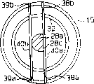
图13是转向销的俯视图。Fig. 13 is a top view of the steering pin.
图14是电位计组装结构主要部分的纵向剖视图。Fig. 14 is a longitudinal sectional view of the main part of the potentiometer assembly structure.
图15是第5实施例所使用的变形抑制部件的立体图。Fig. 15 is a perspective view of a deformation suppressing member used in the fifth embodiment.
图16是表示输出轴与弹性部件二者关系的模式图。Fig. 16 is a schematic diagram showing the relationship between the output shaft and the elastic member.
图17是表示第5实施例的电位计组装结构的局部立体分解图。Fig. 17 is a partially exploded perspective view showing the potentiometer assembly structure of the fifth embodiment.
图18是表示其它例子的电位计组装结构的局部立体分解图。Fig. 18 is a partially exploded perspective view showing another example of an assembly structure of a potentiometer.
图19是表示其它例子的电位计组装结构局部立体分解图。Fig. 19 is a partially exploded perspective view showing another example of an assembly structure of a potentiometer.
图20是表示其它例子的电位计组装结构的局部立体分解图。Fig. 20 is a partially exploded perspective view showing another example of an assembly structure of a potentiometer.
图21是表示以往例中电位计组装结构的立体分解图。Fig. 21 is an exploded perspective view showing an assembly structure of a potentiometer in a conventional example.
实施发明的最佳方式The best way to practice the invention
(第1实施例)(first embodiment)
下面,结合图1~图5对将本发明具体化为对叉车后轴梁的转向销的回转角进行检测的电位计组装结构的第1实施例进行说明。Next, a first embodiment of the present invention embodied as a potentiometer assembly structure for detecting the rotation angle of a steering pin of a rear axle beam of a forklift will be described with reference to FIGS. 1 to 5 .
如图2所示,在叉车的后轴梁1中,由曲杠杆销4可转动地支承通过未图示的方向盘的操作使转向轮2转向的曲杠杆3。后轴梁1的两端设有支承转向轮2的转向节7、8,曲杠杆3通过一对转向杆5、6连结在转向节7、8上。转向杆5的第1端部可转动地连结在固定于曲杠杆3的连结销9a上,第2端部可转动地连结在固定于转向节7的连结销10a上。转向杆6的第1端部可转动地连结在固定于曲杠杆3的连结销9b上,第2端部可转动地连结在固定于转向节8的连结销10b上。As shown in FIG. 2 , in a
图3示出转向轮2支承于后轴梁1中的状态。在后轴梁1的上梁11上固定有作为支承部件的上托架12,下梁13上固定有下托架14。上托架12上形成有在垂直方向上贯通的轴承孔12a,下托架14上形成有在垂直方向上贯通的轴承孔14a。作为转动轴的转向销15,在轴承孔12a和轴承孔14a处分别受到滚针轴承16的支承而能够转动。转向销15上固定有可与之一体转动的转向节7。在转向节7的轴部17上,通过一组圆锥滚柱轴承18、19支承有可转动的转向轮2。FIG. 3 shows the state in which the steered
如图3所示,在上托架12的上表面12a上通过传感器支承部件20组装有作为旋转位移检测器的电位计21。将电位计21以螺钉22固定在传感器支承部件20上。传感器支承部件20通过螺栓23固定在上托架12的上表面12b上。电位计21上连接有引线24。As shown in FIG. 3 , a
传感器支承部件20例如是将铝压铸成板状而形成。如图1和图4所示,在传感器支承部件20的中央部位设有安装孔20a。The
如图1和图4所示,电位计21具有圆柱形的本体部25、设置在本体部25两侧的安装部26、自本体部25的下表面突出的下端部27、以及自该下端部27的下表面突出的输入轴28。下端部27的大小可使其外径进入安装孔20a。各安装部26上分别设有用来将本体部25通过螺钉22固定在传感器支承部件20上的圆弧状长孔26a。输入轴28的前端构成连结轴部28a。在该实施例中,连结轴部28a呈断面为D字形地形成,并且安装有作为弹性连结部件及弹性部件的衬套29。As shown in FIGS. 1 and 4 , the
衬套29例如以合成橡胶制成。衬套29制成由呈圆柱状形成且其中心线与输入轴28的中心线在一条直线上的作为第1胴体部的大直径胴体部29a、以及呈圆柱状形成且其中心线与大直径胴体部29a相平行的作为第2胴体部的小直径胴体部29b组合而成的形状。在衬套29的大直径胴体部29a的中央部位形成有在垂直方向上贯通的、可使连结轴部28a嵌入的卡合孔30。该卡合孔30这样形成,即在与连结轴部28a相嵌合的状态下,衬套29的大直径胴体部29a的中心线与输入轴28的中心线在一条直线上。在该实施例中,由大直径胴体部29a及小直径胴体部29b构成嵌合部,由卡合孔30构成嵌入部。The
另一方面,在转向销15的上部(端部),形成有作为与衬套29嵌合的嵌合凹部的连结孔31。该连结孔31的形状制成由呈圆柱状形成且其中心线与转向销15的中心线在一条直线上的作为第1孔部的大直径孔部31a、以及呈圆柱状形成且其中心线与大直径孔部31a的中心线相平行的作为第2孔部的小直径孔部31b组合而成的形状。而且,所形成的大直径孔部31a可使衬套29的大直径胴体部29a与之嵌合,所形成的小直径孔部31b可使小直径胴体部29b与之嵌合。连结孔31的孔口端部上形成有倾斜部15a。On the other hand, in the upper part (end part) of the
并且,如图4和图5所示,电位计21安装在输入轴28上且通过嵌合于连结孔31内的衬套29而与转向销15相连结。在该实施例中,由连结轴部28a、衬套29以及连结孔31构成转动传递机构。Furthermore, as shown in FIGS. 4 and 5 , the
其次,对如上构成的旋转位移检测器组装结构的作用进行说明。Next, the action of the assembly structure of the rotational displacement detector configured as above will be described.
由于连结孔31制成由各自为圆柱形的大直径孔部31a及小直径孔部31b组合而成的形状,因此,要在转向销15上制作出连结孔31时,只要分别以一次钻孔加工出大直径孔部31a和小直径孔部31b即可形成连结孔31。Since the connecting
在上托架12上组装电位计21时,使装在连结轴部28a上的衬套29穿过上托架12上表面上所固定的传感器支承部件20的安装孔20a而与连结孔31嵌合。此时,即使输入轴28的中心线与转向销15的中心线存在一些偏差,由于受到设在连结孔31孔口端部的倾斜部15a的导向,可使衬套29与连结孔31嵌合。于是,输入轴28通过衬套29与转向销15可一体转动地相连结。When assembling the
在组装好电位计21的状态下,当在未图示的方向盘的操作下曲杠杆3受到操动时,经转向杆5、6驱使转向节7、8动作。并且,仅使转向轮2转动与方向盘转动量的大小相应的转向角。此时,仅使转向销15转动与转向角相应的转动量,输入轴28也同样仅转动相同的转动量。In the state where the
在输入轴28的中心线与转向销15的中心线成一条直线的情况下,转向销15在无弯曲力矩作用于输入轴28的状态下转动,该转动通过衬套29传递给输入轴28,输入轴28仅转动与转向销15相同的转动量。于是,电位计21检测出作为转向销15旋转位移的转动角。When the centerline of the
当输入轴28的中心线与转向销15的中心线之间,由于各零部件尺寸存在分散性或者由于滚针轴承16经长期使用而磨损导致转向销15产生位移等原因而产生偏差时,衬套29将产生弹性变形而容许输入轴28和转向销15二者存在偏差。此时,将由转向销15通过产生弹性变形的衬套29而施加的径向力作用于输入轴28。因此,转向销15向输入轴28施加的径向力被衬套29通过弹性变形吸收而减弱。When there is a deviation between the centerline of the
当转向销15在这种状态下转动时,转向销15的转动经产生弹性变形的衬套29向输入轴28传递。此时,由于输入轴28与转向销15之间未产生间隙,因此,转向销15的转动将原封不动地传递到输入轴28上。因此,输入轴28仅转动与转向销15相同的转动量,故能够以电位计21检测出转向销15的实际转动角。When the
由该实施例能够获得如下效果。The following effects can be obtained by this embodiment.
(1)将输入轴28与转动轴(转向销15)二者以弹性连结部件(衬套29)进行连结,该弹性连结部件不仅能够以弹性变形容许输入轴28的中心线与转动轴的中心线之间存在偏差而且能够限制输入轴28和转动轴二者相对转动。因此,即使输入轴28的中心线与转动轴的中心线之间产生偏差,转动轴对输入轴28施加的径向力因弹性连结部件的弹性变形被吸收而减弱,并且,转动轴的转动能够原封不动地传递到输入轴28上。其结果,能够防止对输入轴28施加的径向力导致旋转位移检测器(电位计21)使用寿命降低或损坏,并且,能够消除转动轴与输入轴28二者在转动方向上旷动而获得较高的检测精度。(1) Connect the
(2)将弹性部件(衬套29)可一体转动地固定在输入轴28上,同时,将弹性部件不可相对转动地嵌合在设在转动轴(转向销15)上设置的连结孔31内。因此,即使输入轴28的中心线与转动轴的中心线之间产生偏差,也能够通过弹性部件的弹性变形而容许存在偏差且以产生弹性变形的弹性部件限制输入轴28与转动轴二者相对转动。而且,弹性部件的加工制造容易。(2) Fix the elastic member (bush 29) to the
(3)将设在输入轴28上的连结轴部28a嵌合在设在弹性部件(衬套29)上的卡合孔30内而使其具有止转功能,将衬套29嵌合在设在转动轴(转向销15)上的连结孔31内而使之具有止转功能。因此,以机械方式限制了输入轴28与衬套29之间以及衬套29与转动轴之间的相对转动,故能够可靠地防止转动轴与输入轴28之间发生转动。其结果,转动轴的转动可切实传递到输入轴28上,故能够提高旋转位移检测器检测精度的可靠性。(3) Fit the connecting
(4)连结孔31与连结轴部28a的形状分别制成不能够相对上述弹性部件作相对转动的形状。因此,即使各部件之间不进行固定连接,也能够在长时期内做到使转动轴(转向销15)的转动切实传递到输入轴28上。(4) The shape of the connecting
(5)衬套29以合成橡胶制成,故其加工制造容易。(5) The
(6)连结孔31制成由分别为圆柱形的大直径孔部31a和小直径孔部31b组合而成的形状。因此,各孔部31a、31b分别经一次钻孔加工即可形成,故能够以较少的加工工时形成连结孔31。(6) The connecting
(7)由于连结孔31的孔口端部设有倾斜部15a,因此,将衬套29嵌合在连结孔31内时,即使输入轴28的中心线与转向销15的中心线之间多少有些偏差,也能够靠倾斜部15a引导衬套29与连结孔31嵌合。其结果,能够容易且迅速地进行旋转位移检测器的组装。(7) Since the opening end of the
(第2实施例)(second embodiment)
下面,对将本发明具体化了的第2实施例结合图6~图8进行说明。该实施例也是对与第1实施例相同的转向销15的转动角进行检测的电位计21的组装结构,因此,对于与第1实施例相同的构成部分赋予相同的编号并省略其详细的说明。另外,在图6中省略了上托架12及传感器支承部件20。Next, a second embodiment of the present invention will be described with reference to FIGS. 6 to 8 . This embodiment is also an assembly structure of the
如图6和图7所示,电位计21的输入轴28与第1实施例不同,连结轴部28a的断面呈圆形。并且,连结轴部28a上形成有与中心线相交且向径向延伸的作为贯穿部的通孔28b。As shown in FIGS. 6 and 7 , the
在转向销15的上端设有可将输入轴28配置在中央部位的作为连结凹部的连结孔32。在转向销15上,隔着中心线而相对的位置上分别设有向径向延伸的、将连结孔32与转向销15的外周面连通的卡合槽33a、33b。两个卡合槽33a、33b设置在沿径向延伸的同一条直线上。在各卡合槽33a、33b的上端形成有倾斜部15b。At the upper end of the
并且,如图8所示,输入轴28的通孔28b中贯穿有作为弹性连结部件及弹簧部件的棒状弹簧34,棒状弹簧34的两端分别压入并嵌合于各卡合槽33a、33b内。棒状弹簧34由钢琴弦制成。在该实施例中,由通孔28b、卡合槽33a、33b以及棒状弹簧34构成转动传递机构。In addition, as shown in FIG. 8 , a rod-shaped
下面,对如上构成的旋转位移检测器的组装结构的作用进行说明。Next, the action of the assembly structure of the rotational displacement detector configured as above will be described.
由于连结孔32为圆柱形,因此,经一次钻孔加工即可在转向销15上形成连结孔32。Since the connecting
在上托架12上组装电位计21时,当将处在贯穿于通孔28b内而卡止在输入轴28上的状态下的棒状弹簧34卡合在转向销15的各卡合槽33a、33b内时,输入轴28即通过棒状弹簧34与转向销15可一体转动地相连结。因此,能够在将棒状弹簧34卡止在输入轴28上的状态下进行组装。此时,即使输入轴28的中心线与转向销15的中心线多少有些偏差,由于可通过倾斜部15b引导棒状弹簧34与卡合槽33a、33b相卡合,因此,能够容易且可靠地与卡合槽33a、33b相卡合。When assembling the
当输入轴28的中心线与转向销15的中心线二者在一条直线上时,转向销15在无弯曲力矩作用于输入轴28的状态下转动,该转动经棒状弹簧34向输入轴28传递。因此,能够以电位计21对转向销15的转动角进行检测。When the centerline of the
当输入轴28的中心线与转向销15的中心线之间产生偏差时,若该偏差的方向在棒状弹簧34的长度方向上,则输入轴28与棒状弹簧34二者的一方将相对于另一方滑动而在长度方向上作相对移动,故而容许输入轴28与转向销15之间存在偏差。另外,若这种偏差在与棒状弹簧34的长度方向相交的方向上,则通过棒状弹簧34产生弹性变形而容许输入轴28与转向销15之间存在偏差。此时,在输入轴28上将作用有由转向销15经产生弹性变形的棒状弹簧34而施加的径向力。因此,转向销15向输入轴28施加的径向力通过棒状弹簧34的弹性变形被吸收而减弱。When there is a deviation between the centerline of the
当转向销15在该状态下转动时,转向销15的转动经产生弹性变形的棒状弹簧34向输入轴28传递。其中,由于棒状弹簧34分别与输入轴28和转向销15卡合,因此,转向销15的转动能够原封不动地传递给输入轴28。因此,能够以电位计21对转向销15的实际转动角进行检测。When the
由该实施例可获得如下效果。The following effects can be obtained from this embodiment.
(1)将输入轴28与转动轴(转向销15)二者以弹性连结部件(棒状弹簧34)进行连结,该弹性连结部件不仅能够以其弹性变形容许输入轴28的中心线与转动轴的中心线之间存在偏差而且能够限制输入轴28和转动轴二者相对转动。因此,即使输入轴28的中心线与转动轴的中心线之间产生偏差,转动轴对输入轴28施加的径向力被吸收而减弱,并且,转动轴的转动能够原封不动地传递到输入轴28上。其结果,能够以简单的结构防止旋转位移检测器使用寿命降低或损坏,并且能够提高检测精度。(1) Both the
(2)将输入轴28配置在设于转动轴(转向销15)上的连结孔32内,并使得在该连结孔32内受到支承的弹簧部件(棒状弹簧34)其中央部位与输入轴28相连结而能够在其长度方向上相对移动。因此,能够以较合成橡胶等弹性部件使用寿命更高的弹簧部件将转动轴和输入轴28二者连结起来,故可靠性提高。(2) The
(3)弹簧部件(棒状弹簧34)贯穿于设在输入轴28上的贯穿部(通孔28b)内。因此,能够切实限制输入轴28与转动轴二者的相对转动而提高可靠性。此外,仅以一根棒状弹簧34连结输入轴28和转向销15,故零部件数量少。并且,棒状弹簧34是卡合在卡合槽33a、33b内的,故棒状弹簧34的更换容易。(3) The spring member (rod spring 34 ) is inserted into a penetration portion (through
(4)棒状弹簧34以钢琴弦制成,故其疲劳极限高,即使长期承受重复载荷也不易损坏,可提高可靠性。而且,不容易生锈,故能够防止因生锈而导致强度降低,在抗破坏方面可进一步提高可靠性。(4) The rod-shaped
(5)设置在各卡合槽33a、33b上端的倾斜部15b在进行组装时能够导引棒状弹簧34与卡合槽33a、33b卡合。因此,旋转位移检测器的组装变得容易。(5) The
(第3实施例)(third embodiment)
其次,结合图9~图11对第3实施例进行说明。该实施例与第2实施例同样,也是对与第1实施例相同的转向销15的转动角进行检测的电位计21的组装结构,因此,对于与第1和第2实施例相同的构成部分赋予相同的编号并省略详细的说明。此外,在图9中,省略了上托架12和传感器支承部件20。Next, a third embodiment will be described with reference to FIGS. 9 to 11 . This embodiment is the same as the second embodiment, and it is also the assembly structure of the
如图9和图10所示,在电位计21的输入轴28上设有与第1实施例同样的连结轴部28a。即,连结轴部28a上设有将圆柱的一部分切除而形成的止转部28c。在转向销15的上端设有与第2实施例同样的连结孔32。此外,在转向销15上,与转向销15的轴心所在的平面相平行且水平延伸的同一条直线上设有将连结孔32的内周面和转向销15的外周面连通的一对卡合孔35a、35b,以取代第2实施例中的卡合槽33a、33b。并且,在转向销15上,与两个卡合孔35a、35b相平行的同一条直线上设有一对卡合孔36a、36b。As shown in FIGS. 9 and 10 , the
并且,如图11所示,在转向销15的一对卡合孔35a、35b内贯穿有作为弹性连结部件及弹簧部件的棒状弹簧37a,在一对卡合孔36a、36b内同样贯穿有棒状弹簧37b。各棒状弹簧37a、37b以钢琴弦制成。以两个棒状弹簧37a、37b夹持输入轴28的连结轴部28a使其不能够相对于转向销15进行相对转动。详细地说就是,棒状弹簧37a的中央部位被推压在连结轴部28a上所形成的平面状止转部28c上,棒状弹簧37b的中央部位被推压在连结轴部28a中与止转部28c相反一侧的位置上。在该实施例中,由连结轴部28a、卡合孔35a、35b、36a、36b以及棒状弹簧37a、37b构成转动传递机构。And, as shown in FIG. 11, a rod-shaped
其次,对如上构成的旋转位移检测器的组装结构的作用进行说明。Next, the action of the assembly structure of the rotational displacement detector configured as above will be described.
在托架12上组装电位计21时,当将输入轴28的连结轴部28a嵌入预先贯穿于转向销15的各卡合孔35a、35b、36a、36b内的棒状弹簧37a、37b之间时,输入轴28即通过两个棒状弹簧37a、37b可一体转动地与转向销15相连结。When assembling the
当输入轴28的中心线与转向销15的中心线在一条直线上时,转向销15在无弯曲力矩作用于输入轴28的状态下转动,该转动经两个棒状弹簧37a、37b向输入轴28传递。因此,能够以电位计21对转向销15的转动角进行检测。When the center line of the
当输入轴28的中心线与转向销15的中心线二者产生偏差时,若该偏差的方向在两个棒状弹簧37a、37b的长度方向上,则输入轴28与棒状弹簧37a、37b二者将在上述长度方向上相对移动,而容许输入轴28与转向销15之间存在偏差。另外,若该偏差在与两个棒状弹簧37a、37b的长度方向相交的方向上,则由于两个棒状弹簧37a、37b产生弹性变形而容许输入轴28与转向销15之间存在偏差。此时,在输入轴28上施加有由转向销15经产生弹性变形的两个棒状弹簧37a、37b而施加的径向力。然而,转向销15对输入轴28施加的径向力通过两个棒状弹簧37a、37b产生弹性变形被吸收而减弱。When the center line of the
当转向销15在该状态下转动时,转向销15的转动经产生弹性变形的两个棒状弹簧37a、37b向输入轴28传递。其中,两个棒状弹簧37a、37b与转向销15嵌合并对输入轴28进行夹持,因此,转向销15的转动能够原封不动地传递给输入轴28。因此,能够以电位计21对转向销15的实际转动角进行检测。When the
由该实施例可获得如下效果。The following effects can be obtained from this embodiment.
(1)将输入轴28与转动轴(转向销15)二者以弹性连结部件(棒状弹簧37a、37b)进行连结,该弹性连结部件不仅能够以其弹性变形容许输入轴28的中心线与转动轴的中心线之间存在偏差而且能够限制输入轴28和转动轴二者相对转动。因此,能够以简单的结构防止旋转位移检测器(电位计21)使用寿命降低或损坏,并且能够提高检测精度。(1) Both the
(2)与第2实施例同样,将输入轴28配置在设于转动轴上的连结孔32内,并在连结孔32内受到支承的弹簧部件(棒状弹簧37a、37b)的中央部位处,将转动轴(转向销15)与输入轴28连结成彼此只能够在该弹簧部件的长度方向上相对移动。因此,能够以较合成橡胶等弹性部件使用寿命更高的弹簧部件构成弹性连结部件,故可靠性提高。(2) Like the second embodiment, the
(3)以一对弹簧部件(棒状弹簧37a、37b)夹持输入轴28的连结轴部28a而使之不能够转动。因此,在输入轴28上只是设置了具有止转部28c的连结轴部28a,故容易加工。并且,只要是电位计21的输入轴28上形成有止转部28c,则市售的电位计21也可不作任何改进而直接使用。(3) The connecting
(4)利用以钢琴弦制成的棒状弹簧37a、37b夹持连结轴部28a。因此,疲劳极限高,即使长期承受重复载荷也不易损坏,故可提高可靠性。而且,由于不容易生锈,因而能够防止因生锈而导致强度降低,在抗破坏方面可进一步提高可靠性。(4) The connecting
(第4实施例)(fourth embodiment)
下面,对第4实施例结合图12~图14进行说明。该实施例与第3实施例的不同点在于,将第3实施例中的卡合孔35a、35b、36a、36b以及棒状弹簧37a、37b改为卡合槽38a、38b、39a、39b以及片状弹簧40a、40b。对于与第3实施例相同的构成部分赋予相同的编号并省略详细的说明。此外,在图12中,省略了上托架12和传感器支承部件20。Next, a fourth embodiment will be described with reference to FIGS. 12 to 14 . The difference between this embodiment and the third embodiment is that the engaging
输入轴28的连结轴部28a的前端形成有倾斜部28d。An
在转向销15的连结孔32的开口侧上端,与转向销15的轴心所在的平面相平行且水平延伸的同一条直线上设有将连结孔32的内周面与转向销15的外周面连通的一对卡合槽38a、38b。另外,在转向销15上,与两个卡合槽38a、38b相平行的同一条直线上设有一对卡合槽39a、39b。At the upper end of the opening side of the
并且,如图13所示,在一对卡合槽38a、38b内压入并嵌合有作为弹性连结部件及弹簧部件的片状弹簧40a,一对卡合槽39a、39b内同样压入并嵌合有片状弹簧40b。以两个片状弹簧40a、40b对连结轴部28a进行夹持。详细地说就是,片状弹簧40a的中央部位被推压在连结轴部28a的止转部28c上,片状弹簧40b的中央部位被推压在连结轴部28a中与止转部28c相反一侧的位置上。And, as shown in FIG. 13, a
在该实施例中,由连结轴部28a、卡合槽38a、38b、39a、39b以及片状弹簧40a、40b构成转动传递机构。In this embodiment, the rotation transmission mechanism is constituted by the
按照如上构成的旋转位移检测器的组装结构,可获得与第3实施例大致相同的效果。According to the assembly structure of the rotational displacement detector constituted as above, substantially the same effect as that of the third embodiment can be obtained.
因此,该实施例除了具有与第3实施例的(1)~(3)同样的效果之外,还具有如下的效果。Therefore, this embodiment has the following effects in addition to the effects (1) to (3) of the third embodiment.
(1)由于是以片状弹簧40a、40b对连结轴部28a进行夹持的,因此,保持片状弹簧的厚度不变而改变宽度即可很容易地将弹簧力调整为合适大小。因此,弹簧力的整定只针对弹簧部件进行而不会对卡合槽38a、38b、39a、39b造成影响,使得整定变得容易。(1) Since the connecting
(2)即使输入轴28的中心线与转向销15的中心线二者存在一些偏差,设置在连结轴部28a下端的倾斜部28d也能够在进行组装时引导连结轴部28a,使之被夹持在两个片状弹簧40a、40b之间。(2) Even if there is some deviation between the center line of the
(第5实施例)(fifth embodiment)
下面,对第5实施例结合图15~图17进行说明。该实施例与第1实施例基本相同,其最大的不同在于,以与输入轴28相嵌合的嵌合部上设置的金属制成的变形抑制部件41的、作为弹性连结部件的衬套42取代连结输入轴28和转向销15二者的、整体由橡胶制成的衬套29。对于与第1实施例相同的构成部分赋予相同的编号并对其详细说明予以省略。另外,在图17中,省略了上托架12和传感器支承部件20。Next, a fifth embodiment will be described with reference to FIGS. 15 to 17 . This embodiment is basically the same as the first embodiment, and the biggest difference is that the metal
如图17所示,与衬套42的卡合孔30相对应的位置上配设有变形抑制部件41。变形抑制部件41是将作为硬质材料的金属片(该实施例中为不锈钢片)通过板金加工弯曲成断面大致呈D字形的形状。变形抑制部件41由平面部41a及从其两端对称地延伸的一对曲面部41b构成,两个曲面部41b的前端之间存在有狭缝43。变形抑制部件41与衬套42的本体42a的长度相同,并且,变形抑制部件41的外表面固定在形成于本体42a上的孔42b的内表面上。并且,变形抑制部件41的内侧成为卡合孔30。在该实施例中,变形抑制部件41是在成型制造本体42a时,以嵌入成型方式成一体地铸入本体42a中的。As shown in FIG. 17 , a
变形抑制部件41的厚度为1mm以下(例如为0.5mm),并且,其内径稍小于连结轴部28a的外径,插入连结轴部28a时,两个曲面部41b张开而嵌合在连结轴部28a上。连结轴部28a的前端形成有倾斜部28d。The
下面,对不同于第1实施例的作用和效果进行说明。在第1实施例中,是在连结轴部28a与形成于衬套29上的卡合孔30相嵌合的状态下,将输入轴28与衬套29二者相连结的。若构成衬套29的橡胶的硬度太高,则不能够吸收输入轴28与转向销15之间中心线的偏差,故橡胶硬度的上限为80左右。Next, operations and effects different from those of the first embodiment will be described. In the first embodiment, both the
衬套29与输入轴28之间传递的力矩会对位于旋转方向前方的、D字形卡合孔30的折角部位施加很大的作用力。并且,由于橡胶的硬度较低,当转向销15的旋转方向改变时,例如,在图16中,由顺时针方向转动的状态改变为向反方向的逆时针方向转动时将产生滞后。即,即使转向销15的中心线与输入轴28的中心线在一条直线的状况下,衬套29与输入轴28之间也将产生扭转。并且,若旋转方向重复改变,滞后将增大,衬套29的使用寿命将降低。The torque transmitted between the
而在本实施例中,由于变形抑制部件41熔覆在构成本体42a的橡胶上,因此,衬套42与输入轴28之间所传递的力矩由变形抑制部件41与橡胶二者的整个熔覆面承受,可减小橡胶的扭转变形。因此,即使旋转方向重复改变,使用寿命也可提高。In this embodiment, since the
此外,当变形抑制部件41制成没有狭缝43的筒状时,若连结轴部28a的外径不小于变形抑制部件41的内径,则组装困难,若连结轴部28a的外径较小,则变形抑制部件41与连结轴部28a之间将产生旷动。而本实施例中,变形抑制部件41不仅形成有狭缝43,而且其内径在组装输入轴28之前较连结轴部28a的外径要小。并且,由于连结轴部28a存在有倾斜部28d,是将变形抑制部件41扩张后插入卡合孔30内的,因此,可将输入轴28在不存在旷量的状态下组装在衬套42上。In addition, when the
而且,由于变形抑制部件41是以不锈钢片经板金加工而制成,故加工简单。并且,不容易生锈,故使用寿命提高。Furthermore, since the
本发明并不限于上述各实施例,例如也可作如下改动。The present invention is not limited to the above-mentioned embodiments, for example, the following modifications can also be made.
(1)在第1实施例中,如图18所示,在转动轴(转向销15)的上部设置作为连结凹部的卡合槽44,将输入轴28的连结轴部28a上所安装的衬套45与该卡合槽44卡合。在这种结构中,只要在转动轴上形成卡合槽44即可,故转动轴的加工容易。其中,衬套45的下端设置有倾斜部45a,以提高组装性。此外,作为这种结构,也可以如第5实施例那样,将变形抑制部件41组装在卡合孔30部分中。(1) In the first embodiment, as shown in FIG. 18, an engaging
(2)在第2实施例中,如图19所示,输入轴28的连结轴部28a上除了设有通孔28b之外,还在沿轴向与其偏离的位置上垂直地设置有水平延伸的通孔28e。另外,在转动轴(转向销15)上,相互垂直的直线上各设有一对卡合槽33a、33b、33c、33d。并且,在各通孔28b、28e中分别贯穿棒状弹簧34a、34b,使棒状弹簧34a压入并嵌合于两个卡合槽33a、33b内,棒状弹簧34b压入并嵌合于两个卡合槽33c、33d内。按照这种结构,以相互垂直的一对棒状弹簧34a、34b将输入轴28和转动轴二者连结,因此,可限制在各弹簧部件长度方向上的移动而提高检测精度,并能够进一步提高可靠性。其中,各卡合槽33a~33d的各自的上端设置有倾斜部46,以提高组装性。(2) In the second embodiment, as shown in FIG. 19 , in addition to the through
(3)在第2实施例中,在转动轴(转向销15)上设置一对卡合孔以取代卡合槽33a、33b,并且,在输入轴28的连结轴部28a上设置卡合槽以取代通孔28b。并且,也可以通过卡合槽与预先贯穿于两个卡合孔内的棒状弹簧34相卡合,从而将输入轴28与转动轴二者连结。(3) In the second embodiment, instead of the engaging
另外,也可以是在转动轴上设置卡合槽并在输入轴28上也设置卡合槽,使棒状弹簧34与二者的卡合槽相卡合,从而将输入轴28与转动轴二者连结。In addition, it is also possible to provide an engaging groove on the rotating shaft and also provide an engaging groove on the
(4)在第2实施例中,如图20所示,在与中心线相交叉而延伸的同一条直线上仅配置一对卡合槽47a、47b,并且,在输入轴28的连结轴部28a上设置狭缝状通孔48。并且,使一片片状弹簧49嵌合于通孔48内并且压入并嵌合于两个卡合槽47a、47b内。按照这种结构,片状弹簧49只要有一片即可,故可减少零部件数量和组装工时。其中,各卡合槽47a、47b的上端分别设有倾斜部50,以提高组装性。(4) In the second embodiment, as shown in FIG. 20, only a pair of
在这里,也可以在输入轴28上设置卡合槽以取代通孔48。Here, an engaging groove may be provided in the
(5)各弹簧部件不限于以金属材料制成,也可以以其它例如高弹性塑料等非金属材料制成。(5) The spring components are not limited to be made of metal materials, and can also be made of other non-metal materials such as high elastic plastics.
(6)弹性部件(衬套29)的材质,只要是具有弹性的材料即可,并不限于合成橡胶,也可以是其它例如天然橡胶、高弹性塑料等。(6) The material of the elastic member (the bushing 29 ) may be any material as long as it has elasticity, and is not limited to synthetic rubber, but may be other materials such as natural rubber and highly elastic plastic.
(7)连结轴部28a的断面形状不限于D字形,也可以是其它正三角形、四边形和椭圆形等形状。此时,第5实施例中,变形抑制部件41的形状应与连结轴部28a的断面形状相对应。(7) The cross-sectional shape of the connecting
(8)棒状弹簧34、34a、34b、37a、37b的断面形状不限于圆形,也可以是其它例如正方形、椭圆形等形状。(8) The cross-sectional shape of the rod-shaped
(9)连结孔31和弹性部件(衬套29)的形状不限于由呈圆柱形的部位所组合而成的形状,也可以是其它例如单一的一个圆柱形。此时,为防止弹性部件与连结孔31或者弹性部件与输入轴28之间相对转动,将两个部件彼此接触的接触面粘接或以螺栓等从侧面进行固定。(9) The shape of the
另外,连结孔31及弹性部件的形状也可以是长方体、正方体、椭圆柱等形状。In addition, the shape of the connecting
(10)也可以是将连结孔设在输入轴28上,并将设置成向转动轴侧突出的连结轴部设置在该连结孔内,以弹性连结部件将连结孔和连结轴部二者连结起来。(10) It is also possible to provide the connecting hole on the
(11)在弹性部件(衬套29)的下端设置将该弹性部件向连结孔31内引导的倾斜部。或者在连结孔31的上端及弹性部件的下端二者上设置将该弹性部件向连结孔31内引导的倾斜部。按照这种结构,也能够对弹性部件进行引导而使之嵌合于连结孔31内,故可提高旋转位移检测器的组装性。(11) An inclined portion for guiding the elastic member into the
(12)各弹簧部件不限于通过压入进行固定,也可以使转动轴外周面的端部弯曲以进行卡止。或者也可以通过粘接端部进行固定。(12) Each spring member is not limited to being fixed by press-fitting, but may be locked by bending the end portion of the outer peripheral surface of the rotating shaft. Alternatively, it can also be fixed by gluing the ends.
(13)并不限于为了对转动轴(转向销15)的旋转位移进行检测而组装在支承部件(上托架12)上的旋转位移检测器(电位计21)的组装结构,也可以实施成其它以检测转向角为目的,例如在曲杠杆销4与曲杠杆3一体转动的叉车中,为了对曲杠杆销4的转动量进行检测而设置在上梁11上的旋转位移检测器的组装结构。(13) It is not limited to the assembly structure of the rotational displacement detector (potentiometer 21) assembled on the supporting member (upper bracket 12) in order to detect the rotational displacement of the rotating shaft (steering pin 15), and may also be implemented as Others for the purpose of detecting the steering angle, for example, in a forklift in which the crank lever pin 4 and the crank lever 3 rotate integrally, in order to detect the rotation amount of the crank lever pin 4, the assembly structure of the rotational displacement detector arranged on the
另外,同样地,也可以实施成为了对转动销9a、9b相对于转向杆5、6的转动量进行检测而设置在转向杆5、6上的旋转位移检测器的组装结构。此外,还可以实施成为了对转动销10a、10b相对于转向杆5、6的转动量进行检测而设置在转向杆5、6上的旋转位移检测器的组装结构。In addition, similarly, an assembly structure may be implemented as a rotational displacement detector provided on the
此外,也可以实施成可对转向角之外的旋转位移进行检测的旋转位移检测器的组装结构。In addition, an assembly structure of a rotational displacement detector capable of detecting rotational displacement other than the steering angle may also be implemented.
(14)在第3实施例中,也可以使用片状弹簧取代棒状弹簧37a、37b。(14) In the third embodiment, leaf springs may be used instead of the rod springs 37a and 37b.
(15)在第4实施例中,也可以使用棒状弹簧取代片状弹簧40a、40b。(15) In the fourth embodiment, bar springs may be used instead of the
(16)在第5实施例中,作为将变形抑制部件41通过嵌入成型方式在成型衬套42时铸入的替代方法,也可以将变形抑制部件41以粘接剂粘接在本体42a上。另外,作为变形抑制部件41,也可以使用省略了狭缝43的筒形部件。此时,为了消除旷量,有必要使所形成的变形抑制部件41的内径能够与连结轴部28a的外径准确匹配。(16) In the fifth embodiment, instead of casting the
(17)变形抑制部件41只要以硬质材料制成即可,也可以由不锈钢之外的金属,例如钢、铜、铝合金等金属制成,或者以金属之外的材料,例如硬质塑料制成。(17) As long as the
(18)旋转位移检测器不限于电位计21,也可以是其它的作为模拟式检测器的旋转差动变压器。另外,也可以是作为数字式检测器的编码器、磁性旋转传感器、分解器等。(18) The rotational displacement detector is not limited to the
(19)不限于叉车,对其它例如高空作业车、起重机等工业车辆也可以实施。此外,不限于工业车辆,对卡车、公共汽车等运输车辆、轿车等乘用车辆也可以实施。(19) Not limited to forklifts, it can also be implemented on other industrial vehicles such as aerial work vehicles and cranes. In addition, it is not limited to industrial vehicles, but can also be implemented on transportation vehicles such as trucks and buses, and passenger vehicles such as cars.
Claims (21)
Applications Claiming Priority (3)
| Application Number | Priority Date | Filing Date | Title |
|---|---|---|---|
| JP12417697 | 1997-05-14 | ||
| JP124176/1997 | 1997-05-14 | ||
| JP124176/97 | 1997-05-14 |
Publications (2)
| Publication Number | Publication Date |
|---|---|
| CN1255968A true CN1255968A (en) | 2000-06-07 |
| CN1236284C CN1236284C (en) | 2006-01-11 |
Family
ID=14878861
Family Applications (1)
| Application Number | Title | Priority Date | Filing Date |
|---|---|---|---|
| CNB988050609A Expired - Fee Related CN1236284C (en) | 1997-05-14 | 1998-05-11 | Structure for fitting rotary displacement sensor |
Country Status (10)
| Country | Link |
|---|---|
| US (1) | US6261182B1 (en) |
| EP (1) | EP0985910B1 (en) |
| JP (1) | JP3286979B2 (en) |
| KR (1) | KR100306943B1 (en) |
| CN (1) | CN1236284C (en) |
| AU (1) | AU719772B2 (en) |
| CA (1) | CA2290474C (en) |
| DE (1) | DE69818459T2 (en) |
| TW (1) | TW561122B (en) |
| WO (1) | WO1998051996A1 (en) |
Cited By (5)
| Publication number | Priority date | Publication date | Assignee | Title |
|---|---|---|---|---|
| CN105649999A (en) * | 2014-11-11 | 2016-06-08 | 杭州三花研究院有限公司 | Automobile electronic pump |
| CN108799348A (en) * | 2017-04-26 | 2018-11-13 | 珠海格力电器股份有限公司 | Connecting device for impeller and motor and air conditioner thereof |
| CN104848780B (en) * | 2014-02-14 | 2018-11-13 | 株式会社东海理化电机制作所 | Rotation angle detection apparatus |
| CN111874100A (en) * | 2020-08-10 | 2020-11-03 | 青岛汽车零部件科技创新服务有限公司 | Port AGV is with turning to drive axle corner sensor device assembly |
| CN114524022A (en) * | 2022-02-25 | 2022-05-24 | 中国重汽集团济南动力有限公司 | Front axle assembly with steering angle measuring mechanism |
Families Citing this family (32)
| Publication number | Priority date | Publication date | Assignee | Title |
|---|---|---|---|---|
| US6190264B1 (en) * | 1999-04-21 | 2001-02-20 | Bi Technologies Corporation | Low-hysteresis coupling for angular-position and torque sensor |
| DE10023196C2 (en) * | 2000-05-11 | 2003-04-03 | Orenstein & Koppel Ag | Device for detecting the angle of rotation between two components |
| JP2002039712A (en) * | 2000-07-27 | 2002-02-06 | Mikuni Corp | Connection structure of non-contact type rotary sensor and rotating shaft |
| US6494471B2 (en) * | 2001-01-09 | 2002-12-17 | New Holland North America, Inc. | Apparatus for sensing an angular position of a wheel of a vehicle about a steering axis |
| FR2841615B1 (en) * | 2002-07-01 | 2004-08-20 | Thiriet Fils | TIP FOR A DEVICE FOR WINDING A ROLL-UP ELEMENT SUCH AS A DRAW OR SIMILAR, IN PARTICULAR A VEHICLE |
| US6939210B2 (en) * | 2003-05-02 | 2005-09-06 | Applied Materials, Inc. | Slurry delivery arm |
| US7296810B2 (en) * | 2004-04-01 | 2007-11-20 | Cnh America Llc | Apparatus and method for installing a sensor in connection with relatively movable members for sensing relative position thereof without adjustment |
| US7543831B2 (en) * | 2004-09-01 | 2009-06-09 | Cnh America Llc | Apparatus for installing a sensor on a kingpin |
| DE102004053743B4 (en) * | 2004-11-06 | 2009-04-30 | Man Nutzfahrzeuge Ag | Steerable axle with rotation angle sensor element for a motor vehicle |
| JP4586616B2 (en) * | 2005-04-14 | 2010-11-24 | 日産自動車株式会社 | Angle detector joint structure |
| GB0510990D0 (en) * | 2005-05-28 | 2005-07-06 | Agco Gmbh | Steering systems |
| JP4578364B2 (en) * | 2005-09-15 | 2010-11-10 | Tcm株式会社 | Steering angle detector |
| DOP2006000267A (en) * | 2005-11-30 | 2009-06-30 | Colgate Palmalive Company | COMPOSITIONS AND CLEANING METHODS |
| KR100889276B1 (en) | 2007-10-11 | 2009-03-17 | 에스제이 주식회사 | Potentiometer with Elastic Coupling |
| FR2952179B1 (en) | 2009-10-30 | 2012-06-01 | Peugeot Citroen Automobiles Sa | TOOLING FOR MEASURING THE GAME OF THE DIFFERENT BALLS PRESENTED ON A VEHICLE TRAIN, AND A METHOD OF CONTROLLING THE SET OF BALLS USING SUCH TOOLS |
| EP2761250B1 (en) * | 2011-09-30 | 2018-01-24 | Wabtec Holding Corp. | Position sensing device for transit shaft and arm assembly |
| FR2990255B1 (en) * | 2012-05-03 | 2015-06-05 | Ntn Snr Roulements | ROTATIONAL DRIVE SYSTEM FOR A MOTOR VEHICLE WHEEL |
| WO2014136174A1 (en) * | 2013-03-04 | 2014-09-12 | 沖マイクロ技研株式会社 | Structure for coupling rotary actuator to driven body |
| US9453537B2 (en) * | 2013-10-31 | 2016-09-27 | Deere & Company | Coupler assembly |
| KR102219446B1 (en) * | 2014-10-27 | 2021-02-25 | 현대모비스 주식회사 | Power transmission apparatus of motor for electro-hydraulic power steering |
| US9588478B1 (en) * | 2016-09-30 | 2017-03-07 | Roy Fan | Drive coupling and transmitting assembly for photosensitive drum and toner cartridges |
| IT201800000717A1 (en) * | 2018-01-11 | 2019-07-11 | Bitron Spa | Angular sensor. |
| CN108612783A (en) * | 2018-05-07 | 2018-10-02 | 西安航空制动科技有限公司 | A kind of elastic connecting device for airplane wheel velocity sensor |
| US10611406B2 (en) * | 2018-05-31 | 2020-04-07 | Deere & Company | Rotary position sensor isolator |
| US10766531B2 (en) * | 2018-08-31 | 2020-09-08 | Cnh Industrial America Llc | Steering sensor pin assembly |
| NL2023750B1 (en) | 2019-09-03 | 2021-04-13 | Terberg Benschop B V | Axle assembly and vehicle comprising such an axle assembly |
| USD949030S1 (en) * | 2020-02-24 | 2022-04-19 | Martin Engineering Company | Sensor device that measures shaft rotation |
| IT202000011581A1 (en) * | 2020-05-19 | 2021-11-19 | Cnh Ind Italia Spa | IMPROVED STEERING ANGLE SENSOR ASSEMBLY |
| WO2022162676A1 (en) * | 2021-02-01 | 2022-08-04 | Ree Automotive Ltd. | Apparatus for measuring steering angle |
| CN113376396B (en) * | 2021-07-05 | 2024-04-16 | 宁波中车时代传感技术有限公司 | Shaft end photoelectric speed sensor |
| US11859658B2 (en) | 2021-08-17 | 2024-01-02 | Cnh Industrial America Llc | Steering sensor drive for articulating ball joint |
| DE102022203618A1 (en) * | 2022-04-11 | 2023-10-12 | Dana Italia S.R.L. | Steering sensor arrangement |
Family Cites Families (15)
| Publication number | Priority date | Publication date | Assignee | Title |
|---|---|---|---|---|
| FR2167265A5 (en) * | 1972-01-11 | 1973-08-24 | Pitner Alfred | |
| US4121476A (en) | 1977-05-16 | 1978-10-24 | Caterpillar Tractor Co. | Flexible drive |
| DE3339470C2 (en) | 1983-10-31 | 1985-10-03 | Lenord u. Bauer & Co GmbH, 4200 Oberhausen | Rotary transducers or transmitters |
| IT1182310B (en) | 1984-10-04 | 1987-10-05 | Elcis Sas Di Battaglino Piccol | ROTARY TRANSDUCER WITH ELASTIC HUB COUPLED DIRECTLY TO A ROTARY SHAFT |
| US4691818A (en) * | 1986-01-27 | 1987-09-08 | The Laitram Corp. | Concealed drive coupling for use with modular screw conveyor |
| JPS62132422U (en) * | 1986-02-14 | 1987-08-21 | ||
| JPS633216A (en) * | 1986-06-24 | 1988-01-08 | Matsushita Electric Ind Co Ltd | Rotational position detector |
| JPS63135111U (en) * | 1987-02-24 | 1988-09-05 | ||
| JPH0816681B2 (en) * | 1990-01-11 | 1996-02-21 | 松下電器産業株式会社 | Revolution sensor |
| JPH04157314A (en) * | 1990-10-19 | 1992-05-29 | Matsushita Electric Ind Co Ltd | Position detector |
| DE9016232U1 (en) | 1990-11-29 | 1991-03-21 | Fa. Andreas Stihl, 71336 Waiblingen | Form-locking coupling for a hand tool |
| FR2678068A1 (en) | 1991-06-18 | 1992-12-24 | Jaeger | IMPROVEMENTS ON DEVICES INCLUDING A ROTATING MOTION TAKE-OFF, IN PARTICULAR FOR A MOTOR VEHICLE SPEED SENSOR. |
| JPH0555768U (en) * | 1991-12-13 | 1993-07-23 | 株式会社三協精機製作所 | Rotation detector |
| JPH10310077A (en) * | 1997-05-12 | 1998-11-24 | Toyota Autom Loom Works Ltd | Steering angle detection device for steering wheel |
| JP3255079B2 (en) * | 1997-05-13 | 2002-02-12 | 株式会社豊田自動織機 | Mounting structure of rotation amount detector |
-
1998
- 1998-05-11 WO PCT/JP1998/002074 patent/WO1998051996A1/en not_active Ceased
- 1998-05-11 DE DE69818459T patent/DE69818459T2/en not_active Expired - Fee Related
- 1998-05-11 JP JP54903998A patent/JP3286979B2/en not_active Expired - Fee Related
- 1998-05-11 AU AU72357/98A patent/AU719772B2/en not_active Ceased
- 1998-05-11 EP EP98919549A patent/EP0985910B1/en not_active Expired - Lifetime
- 1998-05-11 CA CA002290474A patent/CA2290474C/en not_active Expired - Fee Related
- 1998-05-11 US US09/403,890 patent/US6261182B1/en not_active Expired - Fee Related
- 1998-05-11 CN CNB988050609A patent/CN1236284C/en not_active Expired - Fee Related
- 1998-05-13 TW TW087107375A patent/TW561122B/en not_active IP Right Cessation
-
1999
- 1999-11-11 KR KR1019997010416A patent/KR100306943B1/en not_active Expired - Fee Related
Cited By (8)
| Publication number | Priority date | Publication date | Assignee | Title |
|---|---|---|---|---|
| CN104848780B (en) * | 2014-02-14 | 2018-11-13 | 株式会社东海理化电机制作所 | Rotation angle detection apparatus |
| CN105649999A (en) * | 2014-11-11 | 2016-06-08 | 杭州三花研究院有限公司 | Automobile electronic pump |
| CN105649999B (en) * | 2014-11-11 | 2019-03-29 | 浙江三花汽车零部件有限公司 | car electronic pump |
| CN108799348A (en) * | 2017-04-26 | 2018-11-13 | 珠海格力电器股份有限公司 | Connecting device for impeller and motor and air conditioner thereof |
| CN108799348B (en) * | 2017-04-26 | 2024-08-23 | 珠海格力电器股份有限公司 | Connecting device for impeller and motor and air conditioner thereof |
| CN111874100A (en) * | 2020-08-10 | 2020-11-03 | 青岛汽车零部件科技创新服务有限公司 | Port AGV is with turning to drive axle corner sensor device assembly |
| CN111874100B (en) * | 2020-08-10 | 2021-05-28 | 青岛汽车零部件科技创新服务有限公司 | Port AGV is with turning to drive axle corner sensor device assembly |
| CN114524022A (en) * | 2022-02-25 | 2022-05-24 | 中国重汽集团济南动力有限公司 | Front axle assembly with steering angle measuring mechanism |
Also Published As
| Publication number | Publication date |
|---|---|
| CA2290474A1 (en) | 1998-11-19 |
| AU719772B2 (en) | 2000-05-18 |
| EP0985910B1 (en) | 2003-09-24 |
| KR100306943B1 (en) | 2001-09-24 |
| EP0985910A1 (en) | 2000-03-15 |
| WO1998051996A1 (en) | 1998-11-19 |
| TW561122B (en) | 2003-11-11 |
| DE69818459D1 (en) | 2003-10-30 |
| US6261182B1 (en) | 2001-07-17 |
| JP3286979B2 (en) | 2002-05-27 |
| AU7235798A (en) | 1998-12-08 |
| CN1236284C (en) | 2006-01-11 |
| KR20010012462A (en) | 2001-02-15 |
| DE69818459T2 (en) | 2004-07-22 |
| CA2290474C (en) | 2004-08-03 |
| EP0985910A4 (en) | 2000-09-13 |
Similar Documents
| Publication | Publication Date | Title |
|---|---|---|
| CN1236284C (en) | Structure for fitting rotary displacement sensor | |
| US6708796B2 (en) | Electric power steering apparatus | |
| CN102971198B (en) | Steering device | |
| KR100854472B1 (en) | Electric Steering | |
| CN100519300C (en) | Electric power steering apparatus | |
| US9376139B2 (en) | Ball screw having bearing compensation | |
| CN1745013A (en) | Steering device for motor vehicle | |
| CN1537773A (en) | Worm gear mechanism and electric steering device equipped with the worm gear mechanism | |
| JPWO2004052712A1 (en) | Electric power steering device | |
| CN106458243A (en) | Steering column for motor vehicle, threaded rod and spindle nut | |
| EP1876084A1 (en) | Electronic power steering apparatus | |
| CN106103146B (en) | Strut type suspension system | |
| CN1401526A (en) | Automotive steering system | |
| CN106061823A (en) | Position adjustment device for steering wheel | |
| EP3009329A1 (en) | Rack-and-pinion steering gear unit | |
| US11180182B2 (en) | Steering apparatus of vehicle | |
| WO2022196569A1 (en) | Assembly of gear and rotating shaft, and assembly method therefor | |
| KR101034099B1 (en) | Worm Gear Shaft Support System for Electric Power Steering | |
| CN1730964A (en) | Bearing structure | |
| US20100295266A1 (en) | Steering apparatus for a vehicle | |
| CN1177725C (en) | Braking device for two-wheeled vehicles | |
| CN108349529A (en) | Power steering gear and the transfer for having the power steering gear | |
| CA3100463C (en) | Pulley structure | |
| JP4085802B2 (en) | Electric power steering device | |
| US20150266502A1 (en) | Steering device |
Legal Events
| Date | Code | Title | Description |
|---|---|---|---|
| C06 | Publication | ||
| PB01 | Publication | ||
| C10 | Entry into substantive examination | ||
| SE01 | Entry into force of request for substantive examination | ||
| C14 | Grant of patent or utility model | ||
| GR01 | Patent grant | ||
| C17 | Cessation of patent right | ||
| CF01 | Termination of patent right due to non-payment of annual fee |
Granted publication date: 20060111 Termination date: 20100511 |