CN1264183A - Terminal sealing for electrolysis units - Google Patents
Terminal sealing for electrolysis units Download PDFInfo
- Publication number
- CN1264183A CN1264183A CN99126906A CN99126906A CN1264183A CN 1264183 A CN1264183 A CN 1264183A CN 99126906 A CN99126906 A CN 99126906A CN 99126906 A CN99126906 A CN 99126906A CN 1264183 A CN1264183 A CN 1264183A
- Authority
- CN
- China
- Prior art keywords
- base
- connector
- cover
- cylindrical neck
- hole
- Prior art date
- Legal status (The legal status is an assumption and is not a legal conclusion. Google has not performed a legal analysis and makes no representation as to the accuracy of the status listed.)
- Granted
Links
- 238000007789 sealing Methods 0.000 title claims abstract description 10
- 238000005868 electrolysis reaction Methods 0.000 title description 7
- 238000007906 compression Methods 0.000 claims abstract description 11
- 230000006835 compression Effects 0.000 claims abstract description 10
- 125000006850 spacer group Chemical group 0.000 claims description 21
- 238000000034 method Methods 0.000 claims description 8
- 238000003780 insertion Methods 0.000 claims description 3
- 230000037431 insertion Effects 0.000 claims description 3
- 229920006351 engineering plastic Polymers 0.000 claims 1
- 238000010292 electrical insulation Methods 0.000 abstract description 3
- 230000000712 assembly Effects 0.000 abstract 1
- 238000000429 assembly Methods 0.000 abstract 1
- 239000000945 filler Substances 0.000 description 8
- 239000002184 metal Substances 0.000 description 7
- 239000003792 electrolyte Substances 0.000 description 6
- 239000005060 rubber Substances 0.000 description 5
- 238000010276 construction Methods 0.000 description 4
- 238000004519 manufacturing process Methods 0.000 description 4
- 239000000463 material Substances 0.000 description 3
- 239000012811 non-conductive material Substances 0.000 description 3
- 238000005452 bending Methods 0.000 description 2
- 238000007796 conventional method Methods 0.000 description 2
- 238000005260 corrosion Methods 0.000 description 2
- 238000013461 design Methods 0.000 description 2
- 230000004927 fusion Effects 0.000 description 2
- 239000004593 Epoxy Substances 0.000 description 1
- 239000004677 Nylon Substances 0.000 description 1
- 230000001070 adhesive effect Effects 0.000 description 1
- 230000002411 adverse Effects 0.000 description 1
- 239000000919 ceramic Substances 0.000 description 1
- 238000006243 chemical reaction Methods 0.000 description 1
- 239000011248 coating agent Substances 0.000 description 1
- 238000000576 coating method Methods 0.000 description 1
- 230000007797 corrosion Effects 0.000 description 1
- 238000005336 cracking Methods 0.000 description 1
- 238000009792 diffusion process Methods 0.000 description 1
- 238000006073 displacement reaction Methods 0.000 description 1
- 230000000694 effects Effects 0.000 description 1
- 239000011521 glass Substances 0.000 description 1
- 238000001746 injection moulding Methods 0.000 description 1
- 238000009434 installation Methods 0.000 description 1
- 238000009413 insulation Methods 0.000 description 1
- 239000002991 molded plastic Substances 0.000 description 1
- 239000012778 molding material Substances 0.000 description 1
- 229920001778 nylon Polymers 0.000 description 1
- 238000012856 packing Methods 0.000 description 1
- 229920002492 poly(sulfone) Polymers 0.000 description 1
- 230000002265 prevention Effects 0.000 description 1
- 239000000243 solution Substances 0.000 description 1
- 239000011271 tar pitch Substances 0.000 description 1
- 229920001169 thermoplastic Polymers 0.000 description 1
- 239000004416 thermosoftening plastic Substances 0.000 description 1
Images


Classifications
-
- H—ELECTRICITY
- H01—ELECTRIC ELEMENTS
- H01M—PROCESSES OR MEANS, e.g. BATTERIES, FOR THE DIRECT CONVERSION OF CHEMICAL ENERGY INTO ELECTRICAL ENERGY
- H01M50/00—Constructional details or processes of manufacture of the non-active parts of electrochemical cells other than fuel cells, e.g. hybrid cells
- H01M50/10—Primary casings; Jackets or wrappings
- H01M50/172—Arrangements of electric connectors penetrating the casing
-
- H—ELECTRICITY
- H01—ELECTRIC ELEMENTS
- H01M—PROCESSES OR MEANS, e.g. BATTERIES, FOR THE DIRECT CONVERSION OF CHEMICAL ENERGY INTO ELECTRICAL ENERGY
- H01M50/00—Constructional details or processes of manufacture of the non-active parts of electrochemical cells other than fuel cells, e.g. hybrid cells
- H01M50/50—Current conducting connections for cells or batteries
- H01M50/543—Terminals
- H01M50/552—Terminals characterised by their shape
- H01M50/561—Hollow metallic terminals, e.g. terminal bushings
-
- Y—GENERAL TAGGING OF NEW TECHNOLOGICAL DEVELOPMENTS; GENERAL TAGGING OF CROSS-SECTIONAL TECHNOLOGIES SPANNING OVER SEVERAL SECTIONS OF THE IPC; TECHNICAL SUBJECTS COVERED BY FORMER USPC CROSS-REFERENCE ART COLLECTIONS [XRACs] AND DIGESTS
- Y02—TECHNOLOGIES OR APPLICATIONS FOR MITIGATION OR ADAPTATION AGAINST CLIMATE CHANGE
- Y02E—REDUCTION OF GREENHOUSE GAS [GHG] EMISSIONS, RELATED TO ENERGY GENERATION, TRANSMISSION OR DISTRIBUTION
- Y02E60/00—Enabling technologies; Technologies with a potential or indirect contribution to GHG emissions mitigation
- Y02E60/10—Energy storage using batteries
Landscapes
- Chemical & Material Sciences (AREA)
- Chemical Kinetics & Catalysis (AREA)
- Electrochemistry (AREA)
- General Chemical & Material Sciences (AREA)
- Connection Of Batteries Or Terminals (AREA)
- Sealing Battery Cases Or Jackets (AREA)
- Cable Accessories (AREA)
- Electrical Discharge Machining, Electrochemical Machining, And Combined Machining (AREA)
- Seal Device For Vehicle (AREA)
- Connections Effected By Soldering, Adhesion, Or Permanent Deformation (AREA)
Abstract
Description
本发明涉及固定到电解装置的容器的导电端子,尤其是电池端子密封。The present invention relates to electrically conductive terminals secured to vessels of an electrolysis device, in particular battery terminal seals.
众所周知,在制造电化电池的技术中,其关键问题是导电端子和容器罩之间气密密封的结构和保护。有关的问题是反向极电端子的电绝缘,为的是防止短路,该短路会阻碍电池内的电解过程的正当功能。在容器具有金属支承表面的情况下,至少一个极性端子必需与容器气密密封和电绝缘,容器自身可作为第二极端子使用。It is well known that in the art of manufacturing electrochemical cells a key issue is the construction and protection of the hermetic seal between the conductive terminals and the container cover. A related problem is the electrical insulation of the opposite polarity terminals in order to prevent short circuits which would prevent the proper functioning of the electrolysis process within the cell. Where the container has a metal support surface, at least one polarity terminal must be hermetically sealed and electrically insulated from the container, the container itself serving as the second polarity terminal.
美国Hooke等人的并转让给“Hawker Energy Products,Inc.”的第5,663,015号专利公开了一种制造电池端子密封的方法。一具有内螺纹的模制塑料螺母与电池端子的外螺纹配合,通过电池罩中的孔固定端子。端子顶表面和形成在罩中的孔之间的间隙充满固化的填料。当填料还未固化时,螺母被旋转以压缩填料,从而充满端子和罩之间任何间隙。但是Hooke等人公开的方案十分费力,因为当填料处在未凝固状态时,填料的径向和轴向的散布不得不限制在端子、紧固件和端子的顶表面的组合。此外,两个密封零件即填料和O型圈需要受压缩靠向内罩,以便防止电解液的扩散。未固化的填料不形成压缩力。填料固化后,泄漏的防止是根据填料结合的性能。US Patent No. 5,663,015 to Hooke et al. and assigned to "Hawker Energy Products, Inc." discloses a method of making a battery terminal seal. A molded plastic nut with internal threads engages the external threads of the battery terminal to secure the terminal through the aperture in the battery housing. The gap between the top surface of the terminal and the hole formed in the housing is filled with cured filler. While the filler is still uncured, the nut is rotated to compress the filler, thereby filling any gap between the terminal and the shroud. But the solution disclosed by Hooke et al. is laborious because the radial and axial spread of the filler has to be limited to the combination of the terminal, fastener and top surface of the terminal when the filler is in its unset state. In addition, two sealing parts, the packing and the O-ring, need to be compressed against the inner housing in order to prevent the diffusion of the electrolyte. Uncured fillers do not develop compressive forces. After the filler has cured, the prevention of leakage is based on the properties of the filler bond.
加拿大Ching等人转让给“The Gates Rubber Company”的第1,067,958号专利公开了一种分隔密封的连接件,它包括的端子具有加大的和锥形的底部,以便与可变形的导线护套配合,并与定位在连接件底座上倒置的平头圆锥体斜面结合。该底座应具有一定程度的回弹性,以便在相互施加压力的关系下偏置可变形的导线护套。如果连接件底座缺少足够的回弹性,它可能在恒定载荷下蠕变并损害密封。同时Ching等人仅考虑密封电池端子,但它没有考虑到容器和导电端子之间的电绝缘。Patent No. 1,067,958 assigned to "The Gates Rubber Company" by Ching et al. of Canada discloses a compartmentalized sealed connection comprising terminals with enlarged and tapered bases to mate with deformable wire sheaths , combined with an inverted frusto-conical slope positioned on the base of the connector. The base should have a degree of resilience so as to bias the deformable wire sheaths in a mutually exerted pressure relationship. If the connector base lacks sufficient resilience, it may creep under constant load and compromise the seal. Whilst Ching et al. only considered sealing the battery terminals, it did not consider the electrical insulation between the container and the conductive terminals.
加拿大Swenson的第298,379号专利公开了一带有锥形壁的导向螺母,它旋拧在电池端子上,以便围绕端子产生压缩。一中心孔定位在容器顶壁内形成的凸台空腔中,以便容纳电池端子的外部。两个密封零件,橡胶垫片和橡胶衬垫是当螺母向下旋紧在端子上时用于密封中心孔。这种结构不允许使用金属容器,因为导电端子不是电绝缘的。Canadian Patent No. 298,379 to Swenson discloses a guide nut with tapered walls that is threaded over a battery terminal to create compression around the terminal. A central hole is positioned in the boss cavity formed in the top wall of the container to receive the exterior of the battery terminal. Two sealing parts, a rubber washer and a rubber washer, are used to seal the center hole when the nut is screwed down on the terminal. This construction does not allow the use of metal containers because the conductive terminals are not electrically isolated.
因此,需要一简单的导电端子,它能够既用于导电,又用于非导电的支承容器,同时形成良好的密封,以便防止电解液泄漏。Therefore, there is a need for a simple conductive terminal that can be used for both conductive and non-conductive support containers while forming a good seal to prevent electrolyte leakage.
本发明的目的是提供一种简单和廉价的电池端子密封,以便可靠地将导电端子连接到蓄电池的支承罩上,它完全或部分克服了现有技术结构的缺陷。It is an object of the present invention to provide a simple and inexpensive battery terminal seal for securely connecting the conductive terminals to the support housing of the accumulator, which completely or partly overcomes the disadvantages of the prior art constructions.
本发明的另一目的是提供一种电池端子密封,它使用单件式垫片,以便密封和电绝缘导电端子。Another object of the present invention is to provide a battery terminal seal which utilizes a one-piece gasket to seal and electrically insulate the conductive terminals.
本发明的再一目的是提供一种廉价耐用的密封电池端子。Yet another object of the present invention is to provide an inexpensive and durable sealed battery terminal.
在本发明的一实施例中,提供一种电解装置的容器的端子组件。容器罩包括带中心孔的凸台。绝缘垫片具有带中心孔的基部,中心孔由圆柱形颈部环绕,圆柱形颈部从基部的一侧以直角延伸,而一边缘从基部的对置侧以直角延伸。圆柱形颈部具有在内部限定的向外的圆锥环带,它终止于一圆形边缘。圆形边缘直径的尺寸使之搭扣配合在凸台的孔中。连接件具有底座部分,螺纹部分和头部,底座部分大于罩内的孔,螺纹部分从底座部分的一个表面垂直地延伸,而头部从底座的对置表面延伸。螺纹部分设计成容纳在垫片的圆柱形颈部中。锁紧螺母包括法兰和从上述法兰以直角延伸的锥形套。锥形套具有带导向边缘的螺纹中心孔。锥形套的导向边缘具有的外径小于垫片圆形边缘的内径。锁紧螺母的螺纹孔适宜接纳连接件的螺纹部分,以便将锥形套推进到垫片圆柱形颈部里面,从而对圆柱形颈部产生径向和轴向压缩力。圆柱形颈部变形并包盖在凸台的孔周围,从而它成为插入在锁紧螺母的锥形套和连接件的底座部分之间。一个紧密的密封在上述罩、上述连接件和上述锁紧螺母之间形成,同时连接件被固定在容器上。In one embodiment of the present invention, a terminal assembly of a container of an electrolysis device is provided. The container cover includes a boss with a central hole. The insulating spacer has a base with a central hole surrounded by a cylindrical neck extending at a right angle from one side of the base and an edge extending at a right angle from the opposite side of the base. The cylindrical neck has an internally defined outwardly conical annulus which terminates in a rounded edge. The diameter of the circular edge is sized for a snap fit in the hole of the boss. The connector has a base portion larger than the aperture in the housing, a threaded portion extending perpendicularly from one surface of the base portion, and a head extending from an opposite surface of the base. The threaded portion is designed to be received in the cylindrical neck of the gasket. The lock nut includes a flange and a tapered sleeve extending at right angles from said flange. The tapered sleeve has a threaded center hole with a leading edge. The leading edge of the tapered sleeve has an outer diameter that is smaller than the inner diameter of the circular edge of the gasket. The threaded bore of the locknut is adapted to receive the threaded portion of the connector to advance the tapered sleeve into the cylindrical neck of the gasket, thereby exerting radial and axial compressive forces on the cylindrical neck. The cylindrical neck deforms and wraps around the bore of the boss so that it becomes inserted between the conical sleeve of the locknut and the base portion of the connector. A tight seal is formed between said cover, said connector and said jam nut while the connector is secured to the container.
在本发明另一实施例中,提供将端子安装在电解装置容器上的方法。提供一连接件,一可变形的绝缘垫片和一锁紧螺母。该连接件具有底座和从上述底座延伸的螺纹柱。锁紧螺母包括法兰和具有螺纹中心孔的锥形套,该螺纹孔适宜接纳连接件的螺纹柱。绝缘垫片具有带中心孔的基部,该孔由从基部一侧延伸的圆柱形颈部环绕。垫片插入形成在容器罩内的孔中,以便圆柱形颈部通过罩的孔伸出并与之搭扣配合。连接件然后通过垫片的中心孔插入,以便上述螺纹柱被容纳在圆柱形颈部里面,并通过上述罩的孔伸出。当锁紧螺母旋紧在连接件的柱上时,锁紧螺母的锥形套推进到垫片圆柱形颈部的里面,以便对圆柱形颈部产生径向和轴向压缩力。使圆柱形颈部变形并被迫包盖在罩的孔周围,并成为插入在锁紧螺母的锥形套和连接件的底座之间。在罩、连接件和锁紧螺母之间形成紧密的密封。In another embodiment of the invention, a method of installing a terminal on an electrolyzer vessel is provided. A connector, a deformable insulating washer and a lock nut are provided. The connector has a base and a threaded post extending from the base. The lock nut includes a flange and a tapered sleeve with a threaded central bore adapted to receive the threaded post of the connector. The insulating spacer has a base with a central hole surrounded by a cylindrical neck extending from one side of the base. The spacer is inserted into a hole formed in the container cap so that the cylindrical neck protrudes through the hole in the cap and snap fits therewith. The connector is then inserted through the central hole of the washer so that said threaded post is received inside the cylindrical neck and protrudes through the hole of said shroud. When the lock nut is tightened on the post of the connector, the tapered sleeve of the lock nut advances into the inside of the cylindrical neck of the washer to exert radial and axial compressive forces on the cylindrical neck. The cylindrical neck is deformed and forced to wrap around the hole of the cover and become inserted between the conical sleeve of the jam nut and the base of the connector. Forms a tight seal between the hood, connector and jam nut.
按照本发明的电池端子简单,它提供可靠的绝缘和密封,因为它在容器罩上既产生轴向压缩力又产生径向压缩力。不需要精密工具或机械。端子的装配可以手工完成。The battery terminal according to the invention is simple, provides reliable insulation and sealing, because it produces both axial and radial compressive forces on the container cover. No precision tools or machinery are required. Assembly of the terminals can be done by hand.
本发明的另一优点是电池端子的通用性,它既能够用于导电的支承表面电池容器,又能够用于非导电的支承表面电池容器。此外,该端子形成非常良好的泄漏密封,并且这使得它们适宜应用于电解装置。Another advantage of the present invention is the versatility of the battery terminals, which can be used with both conductive and non-conductive support surface battery containers. Furthermore, the terminals form a very good leak seal and this makes them suitable for use in electrolysis devices.
本发明以上和其他的特性,包括零件的各种新型结构和组合的细节,现在将参照附图作特别描述,其中:The above and other features of the invention, including details of various novel configurations and combinations of parts, will now be described more particularly with reference to the accompanying drawings, in which:
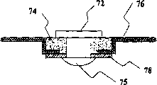
图1A,1B,1C,1D显示用于电解装置的连接件的传统结构;Fig. 1A, 1B, 1C, 1D show the conventional structure of the connector for electrolysis device;
图2是按本发明实施例使用垫片的电解装置的支承罩顶视图;Fig. 2 is the top view of the supporting cover of the electrolysis device using the gasket according to the embodiment of the present invention;
图3是图2沿线3-3处截取的支承罩的剖视图;Fig. 3 is a cross-sectional view of the support cover taken along line 3-3 in Fig. 2;
图4a是应用本发明锁紧螺母的剖视图;Fig. 4 a is the sectional view of applying lock nut of the present invention;
图4b是应用本发明绝缘垫片的剖视图;Fig. 4 b is the cross-sectional view of applying the insulating spacer of the present invention;
图5是按本发明另一实施例的支承罩的立体图;Figure 5 is a perspective view of a support cover according to another embodiment of the present invention;
图6是图5罩的部件分解图,它显示相对罩前所见的端部安装零件;Figure 6 is an exploded view of the cover of Figure 5 showing the end mounting parts seen in front of the cover;
图7是图5罩的部件分解图,它显示相对罩后面所见的端部安装零件;和Figure 7 is an exploded view of the cover of Figure 5 showing the end mounting parts seen relative to the rear of the cover; and
图8是安装在图5支承罩上的连接件剖视图。Fig. 8 is a sectional view of the connector installed on the support cover in Fig. 5 .
图1A到1D显示电池端子的传统安装方法。图1A显示,导电端子52通过非导电的粘接材料层54与金属容器壁56绝缘。层54用陶瓷融合、玻璃融合或环氧树脂粘接。由于这样一种构造,在非导电材料和端子之间没有持久的压缩力,漏电保护是依靠材料的粘接性能。此外,非导电材料的插入加工成本非常昂贵。在端子周围均匀地使用非导电材料而无气泡产生也很困难,而气泡的形成损害粘接性和气密密封。1A to 1D show a conventional installation method of battery terminals. FIG. 1A shows that the
显示在图1B的另一传统技术,是在导电端子62和金属容器壁68的接合处应用橡胶O型圈63。当锁紧螺母64安装在端子62时产生压缩力,压缩力作用在绝缘座圈65和67以及衬垫66和69上,以便压缩O型圈63,将电解液密封在电池容器内。Another conventional technique, shown in FIG. 1B , is to apply a rubber O-
图1C表明电池端子72通过铆钉头75连接在容器的金属罩76上。在这一实施例中,绝缘衬垫78和绝缘座圈74把端子72与罩76密封和电绝缘。FIG. 1C shows that the
上述两个技术的问题是压缩力仅在一个方向产生,即相对端轴线垂直或水平方向。如果压缩力不受控制,结果是结构的不稳定,更易于破裂、断裂和可能泄漏,或者端子对支承罩的连接可能松动,导致电解液泄漏。The problem with the above two techniques is that the compressive force is only generated in one direction, ie perpendicular or horizontal to the opposite end axis. If the compressive force is not controlled, the result is an unstable structure that is more prone to cracking, breaking and possible leakage, or the connection of the terminals to the support housing can become loose, causing electrolyte leakage.
图1D显示将导电端子82连接到金属容器84的另一传统方法。绝缘垫片86围绕端子82定位,以便端子82与容器84密封和电绝缘。当使容器84的外部金属壁88弯曲时产生压缩力,压缩橡胶垫片86靠紧导电端子82,以便将电解液密封在容器84内。但是,弯曲操作的控制是关键。过度的压缩可能引起对垫片的损害,而不足的压缩可能导致电解液的泄漏。压缩比根据装配机械的精度和弯曲模具/辊子设计,它需要一个复杂的制造过程。FIG. 1D shows another conventional method of connecting the
图2是按本发明一实施例安装的具有导电端子的蓄电池顶视图。电池具有设置孔22的支承罩10,以便容纳连接件18和配置在锁紧螺母16和罩10之间的绝缘件12。每个连接件18由锁紧螺母16连接到罩10。用于这个实施例的垫片12与表示在图4、6和7本发明实施例中应用的垫片12完全相同,并参照这些附图进一步描述。Figure 2 is a top view of a battery with conductive terminals installed in accordance with one embodiment of the present invention. The battery has a
图3是图2沿线3-3处截取的罩10的剖视图。罩10具有根据容器确定的外表面13和内表面14。连接件18包括柱19和底座17。底座17大于孔22具有结合面33。当连接件18安装在罩10上时,底座17靠在罩10的内表面14。柱19具有轴向外螺纹。FIG. 3 is a cross-sectional view of
正如图4a所见,锁紧螺母16具有法兰27和从法兰27垂直延伸的锥形套25。套25的内径确定的圆柱壁有轴向螺纹。套25的内螺纹尺寸适于配合地接纳柱19的外螺纹。只要锁紧螺母16沿连接件18的螺纹柱19向下扭转,柱19的纵轴线与锁紧螺母16的纵轴线就成一直线。As can be seen in FIG. 4 a , the
套25的外壁是向内的锥形,朝向导向边缘30。正如图4a也显示的,锁紧螺母16的套25具有高度“h”。The outer wall of the
在整个描述中,使用“向内的”和“向外的”措词是相对于各自零件的纵轴线。Throughout the description, the terms "inwardly" and "outwardly" are used with respect to the longitudinal axis of the respective parts.
图4b更详细地说明垫片12,它具有带中心孔的基部26和从基部26围绕孔22垂直延伸的圆柱形颈部28。圆柱形颈部28设计成搭扣配合在罩10的孔22中。垫片12的中心孔的尺寸使之紧贴地接纳连接件18的螺纹部分19。FIG. 4b illustrates the
正如图4b的显示,圆柱形颈部28的内壁终止于在离开基面26的一区域中向外的锥形环带34。向外的锥形环带34终止于圆形边界32。圆形边界32的直径表示为“D”。直径“D”稍大于锥形套25的前边缘30的直径“d”。垫片12也具有边缘31,它从基部26沿与圆柱形颈部28相反的方向以直角延伸。边缘31的尺寸使之紧密与底座17接合,从而连接件18不能转动。As shown in FIG. 4 b , the inner wall of the
现回过头来参照图3,它显示按本发明的端子组件如何安装在电解装置的罩10上。垫片12由通过孔22伸出的圆柱形颈部28定位在罩10上,基部26邻近罩10的内表面14。然后,连接件18的螺纹部分19插入进垫片12的圆柱形颈部28内部,同时头部17的表面33与垫片12的边缘31紧密接合。最后,各连接件18通过连接件18的螺纹柱19上转动锁紧螺母16固定在罩10上。Referring back now to Figure 3, it is shown how the terminal assembly according to the invention is mounted on the
当锁紧螺母16在连接件18的螺纹柱19上推进时,套25的导向边缘30首先与垫片向外的锥形环带34的圆形边界32接触。其后,锁紧螺母16沿着垫片12的圆柱形颈部28的中心孔和向内的锥形套25被引导,开始压缩可变形垫片12的圆柱形颈部28。逐渐地,颈部28变形并通过锥形套25弯曲在罩10的外表面13之上,并被迫使均匀地包盖在孔22周围。最后,垫片12的圆柱形颈部28被锁紧螺母16的法兰27压缩靠在罩10的表面13,从而垫片12成为插入在锁紧螺母16的锥形套25和连接件18的底座17之间,同时垫片12的基部26受挤压,既靠在罩10的内表面14,又靠在孔22周围。When the
当锁紧螺母16的前边缘30接触底座17时,锁紧螺母16完全定位在端子18上并因此不能再转动,而单件式可变形垫片12覆盖锁紧螺母16和罩10之间存留的所有自由空间。When the
高度“h”以及套25锥形壁的斜角设计成当预定的压力(F)产生在锁紧螺母16和罩10之间时,使锁紧螺母16停止围绕连接件18转动。高度“h”和套25锥形壁的斜角决定锁紧螺母16直至它完全拧紧,它沿连接件18的螺纹部分19能够推进多远,以及在变形状态下垫片12的厚度。因此,垫片12在垂直方向的过度压缩被阻止。同时,提供接触孔22的垫片12部分的足够径向压缩。The height "h" and the bevel angle of the conical wall of the
具有适宜回弹性和绝缘性能,以便制造垫片12的材料是热塑性注塑材料,它具有足够的延伸率和弹性,例如尼龙、聚砜等。The material with suitable resilience and insulating properties to manufacture the
如图3所示,产生在套25和孔22之间的压缩力(F)具有轴向分力(Fv)和径向分力(Fh)。轴向压缩力(Fv)作用在锁紧螺母16的法兰27和底座17的表面33之间,以便沿平行于纵轴线Z-Z’的方向压缩垫片12靠紧罩10的内、外两个表面13和14。径向压缩力(Fh)压缩垫片12靠紧孔22的壁。As shown in FIG. 3, the compressive force (F) generated between the
当连接件18首次安装在罩10上后,垫片12将保持与罩10的连接,使得当需要时连接件18能够容易替换,而无需替换垫片12。为防止腐蚀,在安装垫片12之前,一种反腐蚀涂层例如焦油沥青可以施加在罩10和垫片12上。After the
图5描绘另一实施例的罩10’,它具有凸台15和中心排气孔36。排气孔36释放多余的气体压力,该气体压力可能在电池内的化学反应其间增大。凸台15形成在具有矩形形状的罩10’的外表面13上。圆形孔道22形成在凸台15中心。Figure 5 depicts another embodiment of the cover 10' having a
在这个实施例中,如图6显示,端子18’具有三个部分:外螺纹部分20,头部29和底座部分24。连接件18’的头部29用于与电池内部的电路形成电连接,而且它可以具有适宜这一目的的任何形状和尺寸。在螺纹部分20上还形成一内螺纹孔,以便将外部载荷连接在电池上。In this embodiment, as shown in FIG. 6, the terminal 18' The
图8是图5、6和7的电池连接件18’安装在罩10’上的剖视图。垫片12的凸台15、基面26和连接件18’的底座部分24具有相同的几何形状和预选的尺寸,以便将电池端子固定到容器罩10上。Figure 8 is a cross-sectional view of the battery connector 18' of Figures 5, 6 and 7 installed on the cover 10'.
底座部分24大于孔22,并具有与垫片12的边缘3 1相同的形状。底座部分24的周边设计成被紧密容纳在边缘31内。因此,当连接件18’安装在罩10’上,垫片12就与凸台15中形成的孔22搭扣配合,且连接件18’的底座部分24由垫片12的边缘31围绕,使得连接件18’不能再在孔22内转动。凸台15内零件的设置便于形成紧密的夹紧定位,并防止连接件18’的任何位移,而这种位移可能由锁紧螺母16在连接件18’螺施引起。The
在图5-8描绘的实施例中,凸台15的形状是矩形,但应理解,任何容易的、可制造的形状应是适宜的。锁紧螺母16和垫片12与那些关于图2、3和4实施例的描述相类似。In the embodiment depicted in Figures 5-8, the
为安装端子,执行与图2、3和4实施例的有关描述相同的步骤。导向边缘30的直径“d”和套25的高度“h”的选择是当螺母16与连接件18的底座部分24接触并停止沿螺纹部分20的方向推进时,对绝缘垫片12产生预定的压缩力,正如上文关于对本发明第一实施例的讨论。To install the terminals, the same steps as described in relation to the embodiment of Figs. 2, 3 and 4 are performed. The diameter "d" of the leading
本发明使用带锥形套的锁紧螺母,以便在压缩作用之前,迫使单件式垫片围绕容器的孔并密封连接件。单件式垫片的应用与现有技术的方法相比,现有技术应用多个垫片或多个绝缘零件,而单件式垫片形成单一的结构。螺母16与垫片12和连接件18’结合的设计,使之克服施加过度或不足压缩力的反面效果,也不需要精密工具。The present invention uses a jam nut with a tapered sleeve to force a one-piece gasket around the bore of the container and seal the connection prior to compression. The application of a one-piece spacer is compared to prior art methods which employ multiple spacers or multiple insulating parts, whereas a one-piece spacer forms a single structure. The design of the
按本发明的密封导电端子在电化电池、蓄电池和其他电解装置直接使用的同时,它也能够用在任何需要上述性能的其他电子装置上。While the sealed conductive terminal according to the present invention is directly used in electrochemical cells, accumulators and other electrolytic devices, it can also be used in any other electronic devices requiring the above-mentioned properties.
应当理解,体现本发明的特有端子密封仅以举例的方式公开而不作为本发明的限制。这一发明的原理和特性可以应用在各种和许多的实施例中而不脱离本发明的范围。It should be understood that specific terminal seals embodying the invention are disclosed by way of example only and not as limitations of the invention. The principles and characteristics of this invention may be employed in various and numerous embodiments without departing from the scope of the invention.
Claims (18)
Applications Claiming Priority (2)
| Application Number | Priority Date | Filing Date | Title |
|---|---|---|---|
| CA2256987 | 1998-12-23 | ||
| CA002256987A CA2256987C (en) | 1998-12-23 | 1998-12-23 | Terminal seal for electrolytic devices |
Publications (2)
| Publication Number | Publication Date |
|---|---|
| CN1264183A true CN1264183A (en) | 2000-08-23 |
| CN1223027C CN1223027C (en) | 2005-10-12 |
Family
ID=4163121
Family Applications (1)
| Application Number | Title | Priority Date | Filing Date |
|---|---|---|---|
| CNB991269063A Expired - Fee Related CN1223027C (en) | 1998-12-23 | 1999-12-23 | Terminal sealing for electrolysis units |
Country Status (5)
| Country | Link |
|---|---|
| US (1) | US6183905B1 (en) |
| CN (1) | CN1223027C (en) |
| CA (1) | CA2256987C (en) |
| ES (1) | ES2190684B1 (en) |
| IT (1) | IT1314147B1 (en) |
Cited By (2)
| Publication number | Priority date | Publication date | Assignee | Title |
|---|---|---|---|---|
| CN115667682A (en) * | 2020-04-06 | 2023-01-31 | Avl李斯特有限公司 | Adapter Assemblies and Assemblies of Parts |
| CN116646656A (en) * | 2023-07-03 | 2023-08-25 | 路华置富电子(深圳)有限公司 | Easy-to-assemble cylindrical secondary battery |
Families Citing this family (17)
| Publication number | Priority date | Publication date | Assignee | Title |
|---|---|---|---|---|
| JP3756096B2 (en) * | 2001-10-02 | 2006-03-15 | Necトーキン栃木株式会社 | Sealed battery |
| US6701998B2 (en) | 2002-03-29 | 2004-03-09 | Water Gremlin Company | Multiple casting apparatus and method |
| US7348097B2 (en) * | 2003-06-17 | 2008-03-25 | Medtronic, Inc. | Insulative feed through assembly for electrochemical devices |
| US8701743B2 (en) | 2004-01-02 | 2014-04-22 | Water Gremlin Company | Battery parts and associated systems and methods |
| US7338539B2 (en) | 2004-01-02 | 2008-03-04 | Water Gremlin Company | Die cast battery terminal and a method of making |
| KR100782162B1 (en) * | 2006-06-13 | 2007-12-06 | (주)누리셀 | Reserve battery with all-solid-state thin film battery |
| US20110094892A1 (en) * | 2007-05-10 | 2011-04-28 | Zdenek Cerny | Electrolyser |
| PL2425478T3 (en) | 2009-04-30 | 2019-04-30 | Water Gremlin Co | Battery parts having retaining and sealing features and associated methods of manufacture and use |
| US8272085B2 (en) * | 2009-10-13 | 2012-09-25 | Justin Finch | Boat hammock installation system |
| US9748551B2 (en) | 2011-06-29 | 2017-08-29 | Water Gremlin Company | Battery parts having retaining and sealing features and associated methods of manufacture and use |
| JP5772769B2 (en) * | 2012-09-03 | 2015-09-02 | トヨタ自動車株式会社 | Manufacturing method of sealed battery |
| US9954214B2 (en) | 2013-03-15 | 2018-04-24 | Water Gremlin Company | Systems and methods for manufacturing battery parts |
| US9337451B2 (en) | 2013-07-30 | 2016-05-10 | Johnson Controls Technology Company | System and method for roller interconnection of battery cells |
| US9368908B2 (en) | 2014-04-03 | 2016-06-14 | Akron Brass Company | Electrical terminal assembly |
| WO2018003175A1 (en) * | 2016-06-28 | 2018-01-04 | 日東精工株式会社 | Method for non-penetration joining of members, and non-penetration joining structure |
| US11283141B2 (en) | 2018-12-07 | 2022-03-22 | Water Gremlin Company | Battery parts having solventless acid barriers and associated systems and methods |
| KR20220151467A (en) * | 2021-05-06 | 2022-11-15 | 삼성에스디아이 주식회사 | Secondary Battery |
Family Cites Families (10)
| Publication number | Priority date | Publication date | Assignee | Title |
|---|---|---|---|---|
| CA298379A (en) | 1930-03-18 | Swenson Stanley | Battery post | |
| US3964934A (en) | 1975-05-15 | 1976-06-22 | The Gates Rubber Company | High discharge capability sealed through connector |
| DE2701530C3 (en) * | 1977-01-15 | 1979-06-21 | Accumulatorenwerk Hoppecke Carl Zoellner & Sohn, 5000 Koeln | Device for connecting a connecting cable to the pole of an accumulator |
| US4317870A (en) * | 1980-11-24 | 1982-03-02 | Gould Inc. | Battery termination structure |
| GB8325949D0 (en) * | 1983-09-28 | 1983-11-02 | Tungstone Batteries Ltd | Electric batteries |
| DE3520851A1 (en) * | 1985-06-11 | 1986-12-11 | Deutsche Automobilgesellschaft Mbh, 3000 Hannover | DISASSEMBLABLE GAS AND LIQUID-TIGHT POLD COUPLING FOR A GALVANIC CELL OR BATTERY |
| DE3902632A1 (en) * | 1989-01-30 | 1990-08-16 | Deta Akkumulatoren | Battery |
| US5472802A (en) * | 1993-10-25 | 1995-12-05 | Ovonic Battery Company, Inc. | Sealed hydride batteries, including a new lid-terminal seal and electrode tab collecting comb |
| US5663015A (en) | 1995-10-18 | 1997-09-02 | Hawker Energy Products, Inc. | Sealant gasketing plastic nut battery terminal seal |
| IT1292972B1 (en) * | 1997-04-01 | 1999-02-11 | Olimpio Stocchiero | PERFECTED ELECTROLYTE SEALING GROUP FOR ELECTRIC ACCUMULATORS. |
-
1998
- 1998-12-23 CA CA002256987A patent/CA2256987C/en not_active Expired - Lifetime
-
1999
- 1999-02-12 US US09/250,367 patent/US6183905B1/en not_active Expired - Lifetime
- 1999-12-21 IT IT1999MI002659A patent/IT1314147B1/en active
- 1999-12-21 ES ES009902796A patent/ES2190684B1/en not_active Expired - Fee Related
- 1999-12-23 CN CNB991269063A patent/CN1223027C/en not_active Expired - Fee Related
Cited By (2)
| Publication number | Priority date | Publication date | Assignee | Title |
|---|---|---|---|---|
| CN115667682A (en) * | 2020-04-06 | 2023-01-31 | Avl李斯特有限公司 | Adapter Assemblies and Assemblies of Parts |
| CN116646656A (en) * | 2023-07-03 | 2023-08-25 | 路华置富电子(深圳)有限公司 | Easy-to-assemble cylindrical secondary battery |
Also Published As
| Publication number | Publication date |
|---|---|
| ITMI992659A1 (en) | 2001-06-21 |
| CA2256987C (en) | 2003-01-07 |
| CN1223027C (en) | 2005-10-12 |
| CA2256987A1 (en) | 2000-06-23 |
| IT1314147B1 (en) | 2002-12-04 |
| ES2190684A1 (en) | 2003-08-01 |
| ES2190684B1 (en) | 2004-08-16 |
| ITMI992659A0 (en) | 1999-12-21 |
| US6183905B1 (en) | 2001-02-06 |
Similar Documents
| Publication | Publication Date | Title |
|---|---|---|
| CN1264183A (en) | Terminal sealing for electrolysis units | |
| US4775604A (en) | Method and apparatus for sealing a battery terminal post | |
| CN103125032B (en) | Nonaqueous electrolytic solution secondary battery | |
| CA1297529C (en) | Post seal and method of manufacture for lead-acid batteries | |
| CN1171331C (en) | Cylindrical battery and manufacturing method thereof | |
| US20110212640A1 (en) | Electric, water vapor diffusion resistant pin-and-socket connector | |
| CN1046377C (en) | Connecting devices for terminal posts of battery packs | |
| US5380603A (en) | Battery terminal seal | |
| CN1268253A (en) | V-shaped gaskets for primary cells | |
| CA1283700C (en) | Method and apparatus for sealing a battery terminal post | |
| CN101056778A (en) | Plastic connector for fuel tank | |
| US20050238955A1 (en) | Battery and battery terminal structure and method of manufacture | |
| CN1189955C (en) | Manganese dry battery | |
| CN1343021A (en) | Sealed lead battery | |
| EP1258625A2 (en) | A fuel tank neck seal arrangement | |
| CN114039104B (en) | Leakage-proof valve-controlled lead-acid battery | |
| US5834134A (en) | Sealant gasketing plastic nut battery terminal seal | |
| KR100632247B1 (en) | Bushing for transformer | |
| US6773018B2 (en) | Sealable antenna housing | |
| CN116742243A (en) | battery module | |
| CN1176709A (en) | Tubular seals for battery electrodes | |
| CN214410914U (en) | Terminal assembly and transformer bushing | |
| CN1360321A (en) | Terminal equipment of electric appliance | |
| JP3381999B2 (en) | Epoxy resin mold bushing for gas switch airtight mounting | |
| CN219608135U (en) | Gas meter |
Legal Events
| Date | Code | Title | Description |
|---|---|---|---|
| C10 | Entry into substantive examination | ||
| SE01 | Entry into force of request for substantive examination | ||
| C06 | Publication | ||
| PB01 | Publication | ||
| C14 | Grant of patent or utility model | ||
| GR01 | Patent grant | ||
| CF01 | Termination of patent right due to non-payment of annual fee |
Granted publication date: 20051012 Termination date: 20181223 |
|
| CF01 | Termination of patent right due to non-payment of annual fee |