CN1266373C - Method and device for treating tail gas - Google Patents
Method and device for treating tail gas Download PDFInfo
- Publication number
- CN1266373C CN1266373C CNB021081433A CN02108143A CN1266373C CN 1266373 C CN1266373 C CN 1266373C CN B021081433 A CNB021081433 A CN B021081433A CN 02108143 A CN02108143 A CN 02108143A CN 1266373 C CN1266373 C CN 1266373C
- Authority
- CN
- China
- Prior art keywords
- catalyst
- combustion engine
- internal
- accordance
- engine
- Prior art date
- Legal status (The legal status is an assumption and is not a legal conclusion. Google has not performed a legal analysis and makes no representation as to the accuracy of the status listed.)
- Expired - Fee Related
Links
Images


Classifications
-
- B—PERFORMING OPERATIONS; TRANSPORTING
- B01—PHYSICAL OR CHEMICAL PROCESSES OR APPARATUS IN GENERAL
- B01D—SEPARATION
- B01D53/00—Separation of gases or vapours; Recovering vapours of volatile solvents from gases; Chemical or biological purification of waste gases, e.g. engine exhaust gases, smoke, fumes, flue gases, aerosols
- B01D53/34—Chemical or biological purification of waste gases
- B01D53/92—Chemical or biological purification of waste gases of engine exhaust gases
- B01D53/94—Chemical or biological purification of waste gases of engine exhaust gases by catalytic processes
- B01D53/9459—Removing one or more of nitrogen oxides, carbon monoxide, or hydrocarbons by multiple successive catalytic functions; systems with more than one different function, e.g. zone coated catalysts
-
- B—PERFORMING OPERATIONS; TRANSPORTING
- B01—PHYSICAL OR CHEMICAL PROCESSES OR APPARATUS IN GENERAL
- B01D—SEPARATION
- B01D53/00—Separation of gases or vapours; Recovering vapours of volatile solvents from gases; Chemical or biological purification of waste gases, e.g. engine exhaust gases, smoke, fumes, flue gases, aerosols
- B01D53/34—Chemical or biological purification of waste gases
- B01D53/92—Chemical or biological purification of waste gases of engine exhaust gases
- B01D53/94—Chemical or biological purification of waste gases of engine exhaust gases by catalytic processes
- B01D53/9495—Controlling the catalytic process
-
- F—MECHANICAL ENGINEERING; LIGHTING; HEATING; WEAPONS; BLASTING
- F01—MACHINES OR ENGINES IN GENERAL; ENGINE PLANTS IN GENERAL; STEAM ENGINES
- F01N—GAS-FLOW SILENCERS OR EXHAUST APPARATUS FOR MACHINES OR ENGINES IN GENERAL; GAS-FLOW SILENCERS OR EXHAUST APPARATUS FOR INTERNAL-COMBUSTION ENGINES
- F01N13/00—Exhaust or silencing apparatus characterised by constructional features
- F01N13/009—Exhaust or silencing apparatus characterised by constructional features having two or more separate purifying devices arranged in series
-
- F—MECHANICAL ENGINEERING; LIGHTING; HEATING; WEAPONS; BLASTING
- F01—MACHINES OR ENGINES IN GENERAL; ENGINE PLANTS IN GENERAL; STEAM ENGINES
- F01N—GAS-FLOW SILENCERS OR EXHAUST APPARATUS FOR MACHINES OR ENGINES IN GENERAL; GAS-FLOW SILENCERS OR EXHAUST APPARATUS FOR INTERNAL-COMBUSTION ENGINES
- F01N3/00—Exhaust or silencing apparatus having means for purifying, rendering innocuous, or otherwise treating exhaust
- F01N3/08—Exhaust or silencing apparatus having means for purifying, rendering innocuous, or otherwise treating exhaust for rendering innocuous
- F01N3/0807—Exhaust or silencing apparatus having means for purifying, rendering innocuous, or otherwise treating exhaust for rendering innocuous by using absorbents or adsorbents
- F01N3/0814—Exhaust or silencing apparatus having means for purifying, rendering innocuous, or otherwise treating exhaust for rendering innocuous by using absorbents or adsorbents combined with catalytic converters, e.g. NOx absorption/storage reduction catalysts
-
- F—MECHANICAL ENGINEERING; LIGHTING; HEATING; WEAPONS; BLASTING
- F01—MACHINES OR ENGINES IN GENERAL; ENGINE PLANTS IN GENERAL; STEAM ENGINES
- F01N—GAS-FLOW SILENCERS OR EXHAUST APPARATUS FOR MACHINES OR ENGINES IN GENERAL; GAS-FLOW SILENCERS OR EXHAUST APPARATUS FOR INTERNAL-COMBUSTION ENGINES
- F01N3/00—Exhaust or silencing apparatus having means for purifying, rendering innocuous, or otherwise treating exhaust
- F01N3/08—Exhaust or silencing apparatus having means for purifying, rendering innocuous, or otherwise treating exhaust for rendering innocuous
- F01N3/0807—Exhaust or silencing apparatus having means for purifying, rendering innocuous, or otherwise treating exhaust for rendering innocuous by using absorbents or adsorbents
- F01N3/0828—Exhaust or silencing apparatus having means for purifying, rendering innocuous, or otherwise treating exhaust for rendering innocuous by using absorbents or adsorbents characterised by the absorbed or adsorbed substances
- F01N3/0842—Nitrogen oxides
-
- F—MECHANICAL ENGINEERING; LIGHTING; HEATING; WEAPONS; BLASTING
- F01—MACHINES OR ENGINES IN GENERAL; ENGINE PLANTS IN GENERAL; STEAM ENGINES
- F01N—GAS-FLOW SILENCERS OR EXHAUST APPARATUS FOR MACHINES OR ENGINES IN GENERAL; GAS-FLOW SILENCERS OR EXHAUST APPARATUS FOR INTERNAL-COMBUSTION ENGINES
- F01N3/00—Exhaust or silencing apparatus having means for purifying, rendering innocuous, or otherwise treating exhaust
- F01N3/08—Exhaust or silencing apparatus having means for purifying, rendering innocuous, or otherwise treating exhaust for rendering innocuous
- F01N3/10—Exhaust or silencing apparatus having means for purifying, rendering innocuous, or otherwise treating exhaust for rendering innocuous by thermal or catalytic conversion of noxious components of exhaust
- F01N3/18—Exhaust or silencing apparatus having means for purifying, rendering innocuous, or otherwise treating exhaust for rendering innocuous by thermal or catalytic conversion of noxious components of exhaust characterised by methods of operation; Control
- F01N3/20—Exhaust or silencing apparatus having means for purifying, rendering innocuous, or otherwise treating exhaust for rendering innocuous by thermal or catalytic conversion of noxious components of exhaust characterised by methods of operation; Control specially adapted for catalytic conversion
- F01N3/2006—Periodically heating or cooling catalytic reactors, e.g. at cold starting or overheating
-
- F—MECHANICAL ENGINEERING; LIGHTING; HEATING; WEAPONS; BLASTING
- F02—COMBUSTION ENGINES; HOT-GAS OR COMBUSTION-PRODUCT ENGINE PLANTS
- F02D—CONTROLLING COMBUSTION ENGINES
- F02D41/00—Electrical control of supply of combustible mixture or its constituents
- F02D41/30—Controlling fuel injection
- F02D41/3011—Controlling fuel injection according to or using specific or several modes of combustion
- F02D41/3017—Controlling fuel injection according to or using specific or several modes of combustion characterised by the mode(s) being used
- F02D41/3023—Controlling fuel injection according to or using specific or several modes of combustion characterised by the mode(s) being used a mode being the stratified charge spark-ignited mode
-
- F—MECHANICAL ENGINEERING; LIGHTING; HEATING; WEAPONS; BLASTING
- F02—COMBUSTION ENGINES; HOT-GAS OR COMBUSTION-PRODUCT ENGINE PLANTS
- F02D—CONTROLLING COMBUSTION ENGINES
- F02D41/00—Electrical control of supply of combustible mixture or its constituents
- F02D41/30—Controlling fuel injection
- F02D41/38—Controlling fuel injection of the high pressure type
- F02D41/40—Controlling fuel injection of the high pressure type with means for controlling injection timing or duration
- F02D41/402—Multiple injections
-
- F—MECHANICAL ENGINEERING; LIGHTING; HEATING; WEAPONS; BLASTING
- F02—COMBUSTION ENGINES; HOT-GAS OR COMBUSTION-PRODUCT ENGINE PLANTS
- F02P—IGNITION, OTHER THAN COMPRESSION IGNITION, FOR INTERNAL-COMBUSTION ENGINES; TESTING OF IGNITION TIMING IN COMPRESSION-IGNITION ENGINES
- F02P5/00—Advancing or retarding ignition; Control therefor
- F02P5/04—Advancing or retarding ignition; Control therefor automatically, as a function of the working conditions of the engine or vehicle or of the atmospheric conditions
- F02P5/145—Advancing or retarding ignition; Control therefor automatically, as a function of the working conditions of the engine or vehicle or of the atmospheric conditions using electrical means
- F02P5/15—Digital data processing
- F02P5/1502—Digital data processing using one central computing unit
- F02P5/1506—Digital data processing using one central computing unit with particular means during starting
-
- F—MECHANICAL ENGINEERING; LIGHTING; HEATING; WEAPONS; BLASTING
- F01—MACHINES OR ENGINES IN GENERAL; ENGINE PLANTS IN GENERAL; STEAM ENGINES
- F01N—GAS-FLOW SILENCERS OR EXHAUST APPARATUS FOR MACHINES OR ENGINES IN GENERAL; GAS-FLOW SILENCERS OR EXHAUST APPARATUS FOR INTERNAL-COMBUSTION ENGINES
- F01N2430/00—Influencing exhaust purification, e.g. starting of catalytic reaction, filter regeneration, or the like, by controlling engine operating characteristics
- F01N2430/08—Influencing exhaust purification, e.g. starting of catalytic reaction, filter regeneration, or the like, by controlling engine operating characteristics by modifying ignition or injection timing
-
- F—MECHANICAL ENGINEERING; LIGHTING; HEATING; WEAPONS; BLASTING
- F02—COMBUSTION ENGINES; HOT-GAS OR COMBUSTION-PRODUCT ENGINE PLANTS
- F02D—CONTROLLING COMBUSTION ENGINES
- F02D41/00—Electrical control of supply of combustible mixture or its constituents
- F02D41/30—Controlling fuel injection
- F02D41/38—Controlling fuel injection of the high pressure type
- F02D2041/389—Controlling fuel injection of the high pressure type for injecting directly into the cylinder
-
- Y—GENERAL TAGGING OF NEW TECHNOLOGICAL DEVELOPMENTS; GENERAL TAGGING OF CROSS-SECTIONAL TECHNOLOGIES SPANNING OVER SEVERAL SECTIONS OF THE IPC; TECHNICAL SUBJECTS COVERED BY FORMER USPC CROSS-REFERENCE ART COLLECTIONS [XRACs] AND DIGESTS
- Y02—TECHNOLOGIES OR APPLICATIONS FOR MITIGATION OR ADAPTATION AGAINST CLIMATE CHANGE
- Y02T—CLIMATE CHANGE MITIGATION TECHNOLOGIES RELATED TO TRANSPORTATION
- Y02T10/00—Road transport of goods or passengers
- Y02T10/10—Internal combustion engine [ICE] based vehicles
- Y02T10/12—Improving ICE efficiencies
-
- Y—GENERAL TAGGING OF NEW TECHNOLOGICAL DEVELOPMENTS; GENERAL TAGGING OF CROSS-SECTIONAL TECHNOLOGIES SPANNING OVER SEVERAL SECTIONS OF THE IPC; TECHNICAL SUBJECTS COVERED BY FORMER USPC CROSS-REFERENCE ART COLLECTIONS [XRACs] AND DIGESTS
- Y02—TECHNOLOGIES OR APPLICATIONS FOR MITIGATION OR ADAPTATION AGAINST CLIMATE CHANGE
- Y02T—CLIMATE CHANGE MITIGATION TECHNOLOGIES RELATED TO TRANSPORTATION
- Y02T10/00—Road transport of goods or passengers
- Y02T10/10—Internal combustion engine [ICE] based vehicles
- Y02T10/40—Engine management systems
Landscapes
- Engineering & Computer Science (AREA)
- Chemical & Material Sciences (AREA)
- Combustion & Propulsion (AREA)
- Mechanical Engineering (AREA)
- General Engineering & Computer Science (AREA)
- Chemical Kinetics & Catalysis (AREA)
- Health & Medical Sciences (AREA)
- Biomedical Technology (AREA)
- Environmental & Geological Engineering (AREA)
- Analytical Chemistry (AREA)
- General Chemical & Material Sciences (AREA)
- Oil, Petroleum & Natural Gas (AREA)
- Signal Processing (AREA)
- Theoretical Computer Science (AREA)
- Toxicology (AREA)
- Exhaust Gas After Treatment (AREA)
- Electrical Control Of Air Or Fuel Supplied To Internal-Combustion Engine (AREA)
Abstract
本发明涉及一种对强制点火式内燃机(10)的尾气进行处理的方法和装置。根据本发明,尾气流过一后置于内燃机(10)的催化系统(16、18),所述催化系统至少由一内燃机附近的预催化剂(16)构成并且预催化剂(16)具有的与内燃机排量相关的惰性金属含量EMVH,最高为1.1g/升(31g/英尺3)内燃机(10)排量,并且在内燃机(10)冷起动后至少瞬时采取至少一种加热措施,从而在发动机起动后至迟25秒可达到至少150℃,其中超过最大发动机转速2500分钟-1的时间最多不超过一秒钟。
The invention relates to a method and a device for treating the exhaust gas of a positive ignition internal combustion engine (10). According to the invention, the exhaust gas flows through a catalytic system (16, 18) downstream of the internal combustion engine (10), said catalytic system consisting at least of a precatalyst (16) in the vicinity of the internal combustion engine and having a a displacement-related inert metal content EM VH up to 1.1 g/l (31 g/ ft3 ) of the internal combustion engine (10) displacement and at least one heating measure is taken at least momentarily after a cold start of the internal combustion engine (10) so that the engine At least 150 °C can be reached no later than 25 seconds after starting, of which the maximum engine speed of 2500 min -1 is exceeded for no more than one second.
Description
技术领域technical field
本发明涉及一种对强制点火式内燃机的尾气进行处理的方法和装置。The invention relates to a method and a device for treating exhaust gas of a forced ignition internal combustion engine.
背景技术Background technique
在内燃机的尾气通道内应用催化剂,以便将内燃机尾气内的有害物质转换成尽可能对环境不造成影响的成分。为保持催化剂处于工作状态,必须将催化剂至少加热到起始温度或熄灯温度。由于至少第一催化剂特别是在内燃机冷启动后通常在一定的时间段内尚不具有起始温度,所以尾气在该时间段内在很大程度上未加转换地被排放到大气中。已知有各种加快催化剂加热过程和减少在加热过程期间的有害物质排放的措施。Catalysts are used in the exhaust gas tract of internal combustion engines in order to convert harmful substances in the exhaust gas of internal combustion engines into components that are as environmentally friendly as possible. To keep the catalyst in working condition, the catalyst must be heated to at least the starting or lights-out temperature. Since at least the first catalyst usually does not yet have a starting temperature for a certain period of time, especially after a cold start of the internal combustion engine, the exhaust gas is emitted largely unconverted into the atmosphere during this period. Various measures are known to speed up the catalyst heating process and to reduce the emissions of pollutants during the heating process.
通常在加热过程中以具有最大效率的点火角为基准迟后调整在汽缸中空-燃-混合气点火的点火角度。通过对点火角的迟后调整将降低燃烧的工作效率并同时提高尾气温度。迟后点火就点火角而言将受到如下因素的制约,其中将会以不容许的方式增大内燃机不平稳的运转或不能保证可靠的点火。另外还已知这种催化剂加热措施不是在λ=1的化学计量的尾气组分的情况下,而是在λ>1的略稀的尾气的情况下实施的。该措施考虑到,由于在稀尾气中存在有剩余的氧,碳氢化合物和一氧化碳转化的起始温度大约低于化学计量的尾气情况时的50至100K。因而在供给稀混合气时将提前有效地开始对有害物质的转换。Usually during the heating process, the ignition angle with the maximum efficiency is used as the reference to adjust the ignition angle of the air-fuel-air mixture ignition in the cylinder later. By adjusting the ignition angle late, the efficiency of the combustion will be reduced and the temperature of the exhaust gas will be increased at the same time. A late ignition is subject to factors with respect to the ignition angle, in which the uneven running of the internal combustion engine is increased in an unacceptable manner or reliable ignition cannot be guaranteed. It is also known that such catalyst heating measures are carried out not with a stoichiometric exhaust gas composition with λ=1, but with a slightly lean exhaust gas with λ>1. This measure takes into account that, due to the presence of residual oxygen in the lean tail gas, the onset temperature of the conversion of hydrocarbons and carbon monoxide is approximately 50 to 100 K lower than in the case of a stoichiometric tail gas. Therefore, the conversion of harmful substances will be effectively started in advance when the lean mixture is supplied.
为减少在加热过程阶段的排放,另外可采用小容积的预催化剂,所述预催化剂设置在尾气设施靠近发动机的位置。由于预催化剂的加热质量小并且靠近发动机,因而可相对较快地达到起始温度,因而可以弥补在下游设置的大容积的主催化剂实现工作温度前的空白。通常作为氧化或三元催化剂设计的预催化剂在其催化覆层-所谓的(催化剂)夹层-中具有较高含量的惰性金属,尤其是铂族惰性金属。因而可以降低催化剂温度,在该温度下可以充分进行有害物质的转化并因此可以实现提前开始转化。其中根据法律规定的污染极限值选定惰性金属的含量。例如在采用目前的加热措施时,可靠的满足欧洲尾气排放标准EU-IV级所要求的专门的惰性金属含量至少为1.3g/升(内燃机排量)。由于惰性金属价格很高,所以满足严格的尾气排放标准势必始终伴随着很高的材料费用开销。In order to reduce emissions during the heating process phase, a small-volume pre-catalyst can additionally be used, said pre-catalyst being arranged in the position of the exhaust system close to the engine. Due to the small heating mass of the pre-catalyst and its proximity to the engine, the initial temperature can be reached relatively quickly, thereby filling the gap before the large-volume main catalyst located downstream reaches the operating temperature. Precatalysts, which are usually designed as oxidation or three-way catalysts, have a relatively high content of inert metals, especially platinum group inert metals, in their catalytic coating—the so-called (catalyst) interlayer. It is thus possible to lower the catalyst temperature at which the conversion of the harmful substances can take place sufficiently and thus an earlier start of the conversion can be achieved. Among them, the content of inert metals is selected according to the pollution limit values stipulated by law. For example, when the current heating measures are adopted, the specific inert metal content required to reliably meet the European exhaust emission standard EU-IV level is at least 1.3g/liter (internal combustion engine displacement). Due to the high price of inert metals, meeting stringent exhaust emission standards always entails high material costs.
发明说明Description of the invention
所以本发明的目的在于提出一种用于对尾气进行净化的方法和装置,所述方法和装置可以以较低的代价保持低排放的极限值。It is therefore the object of the present invention to provide a method and a device for cleaning exhaust gases which make it possible to maintain low emission limit values at low cost.
本发明的目的应用下述方法和装置得以实现:The object of the present invention uses following method and device to realize:
一种强制点火式内燃机的尾气的处理方法,其中A treatment method for exhaust gas of a forced ignition internal combustion engine, wherein
尾气流过后置于内燃机的催化系统,所述催化系统至少由一设置在内燃机附近的预催化剂构成,并且在内燃机起动后至少瞬间采取一种加热措施,预催化剂具有的与内燃机排量相关的惰性金属含量EMVH最高为1.1g/升(31g/英尺3)(内燃机排量),和After the exhaust gas flows through, it is placed in the catalytic system of the internal combustion engine. The catalytic system consists of at least one pre-catalyst arranged in the vicinity of the internal combustion engine and adopts a heating measure at least momentarily after the internal combustion engine is started. The pre-catalyst has an inertness related to the displacement of the internal combustion engine. Metal content EM VH up to 1.1g/l (31g/ ft3 ) (internal combustion engine displacement), and
预催化剂的催化剂温度TVK至少在内燃机起动后至迟25秒达到至少150℃,其中超过最高发动机转速2500分钟-1的时间最多不超过1秒钟。The catalyst temperature T VK of the precatalyst reaches at least 150° C. at the latest 25 seconds after starting the internal combustion engine, wherein the maximum engine speed of 2500 min −1 is exceeded for no more than 1 second.
本发明的方法在第一方面中包括对预催化剂的快速加热,其中在此的出发点是环境和汽车温度为+20℃,相对湿度为30%至70%的标准条件下起动发动机。其中催化剂温度系指在气体入口面的下游侧20mm处的预催化剂的催化覆层(中间层)的温度,其中在此处至少50%的催化剂截面面积具有该温度。根据本方法的特别有益的设计,在发动机起动后至迟20秒钟,尤其在发动机起动后至迟15秒钟,优选在发动机起动后至迟12秒钟可以达到至少为170℃的催化剂温度,优选可以达到至少为200℃的催化剂温度。其中超过特别是1800分钟-1的发动机最大转速,优选最高1200分钟-1的发动机转速的时间最多不超过1秒钟,其中优选对内燃机未加载。The method according to the invention comprises, in a first aspect, rapid heating of the precatalyst, wherein the starting point here is to start the engine under standard conditions of ambient and vehicle temperature of +20° C. and relative humidity of 30% to 70%. The catalyst temperature here refers to the temperature of the catalytic coating (middle layer) of the pre-catalyst at 20 mm downstream of the gas inlet face, wherein at least 50% of the cross-sectional area of the catalyst has this temperature. According to a particularly advantageous configuration of the method, a catalyst temperature of at least 170° C. can be reached no later than 20 seconds after the engine start, especially no later than 15 seconds after the engine start, preferably no later than 12 seconds after the engine start, Catalyst temperatures of at least 200° C. are preferably achievable. In this case, a maximum engine speed of in particular 1800 min −1 , preferably an engine speed of at most 1200 min −1 , is exceeded for at most 1 second, wherein the internal combustion engine is preferably unloaded.
这种快速加热的过程要求采取加热措施,但应用通常的加热方法是不能达到其加热能力的。尤其是设有一点火角迟后调整装置,其中将点火角控制在至少在点火上死点ZOT后的10°。特别优选的是在直接喷射和分层供气的内燃机的情况下采用多次喷射的方法作为另一种加热措施。其中在一汽缸的工作周期中输入的燃料总量以至少两个喷射过程输入到汽缸的燃烧室内。在汽缸的吸入冲程中进行第一次最初的喷射(均匀喷射),从而使在下一个点火时间点前喷入的燃料在燃烧室内具有充分均匀的分布。第二次在后的喷射(分层喷射)与此相反是在接着的压缩冲程中,尤其是在压缩冲程中的后半部分进行的并因而导致所谓的分层供油,其中被喷入的燃料以层状油雾的形式基本集中在汽缸的火花塞的范围内。因而在内燃机的多次喷射工作时形成分层供油和均匀供油的混合工作。优选选定的多次喷射的的燃油分量应使采用均匀喷射形成的是非常稀的,不能单独点火的空-燃-混合气,所述空-燃-混合气只有利用分层供油才能燃烧。与纯均匀工作相比,多次喷射工作由于其特殊的燃烧过程将会导致尾气温度的提高。此外,多次喷射的另一个优点是将降低氮氧化物NOx和未燃烧的碳氢化合物HC的原排放,并将随之减少在加热过程中有害物质的裂解。This rapid heating process requires heating measures, but the application of common heating methods cannot achieve its heating capacity. In particular, an ignition angle retardation device is provided, wherein the ignition angle is controlled to at least 10° behind the ignition top dead center ZOT. It is particularly preferred to use the method of multiple injection as a further heating measure in the case of internal combustion engines with direct injection and stratified gas supply. In this case, the total amount of fuel supplied during a cylinder's working cycle is supplied into the combustion chamber of the cylinder in at least two injection operations. The first initial injection (homogeneous injection) takes place during the intake stroke of the cylinder, so that the injected fuel before the next ignition point in time has a sufficiently uniform distribution in the combustion chamber. The second, subsequent injection (stratified injection) takes place in the subsequent compression stroke, especially in the second half of the compression stroke, and thus leads to a so-called stratified charge, in which the injected The fuel is basically concentrated in the range of the spark plug of the cylinder in the form of layered oil mist. A mixed operation of stratified fuel supply and homogeneous fuel supply is thus formed during the multiple injection operation of the internal combustion engine. Preferably, the fuel fraction selected for the multiple injections is such that the homogeneous injection results in a very lean air-fuel-mixture which cannot be ignited individually and which can only be combusted by means of a stratified fuel supply . Compared with pure homogeneous work, multiple injection work will lead to an increase in exhaust gas temperature due to its special combustion process. In addition, another advantage of multiple injection is that the original emissions of nitrogen oxides NOx and unburned hydrocarbons HC will be reduced, and the cracking of harmful substances in the heating process will be reduced accordingly.
与纯均匀工作方式相比,特别在分层喷射的喷射角度迟后的情况下多次喷射将可以实现特别迟后的点火角度和随之的极限尾气温度。此迟后的分层喷射的一端至少瞬时被控制在其喷射角度在ZOT前的80°至10°,尤其在ZOT前的60°至25°,优选在ZOT前的50°至35°。其中将点火角度尤其控制在ZOT后的至少20°,优选控制在ZOT后的至少35°,其中在此考虑到将导致运转不平稳的增大,因而不得超过ZOT后的最大点火角45°。替代多次喷射和对点火角的迟后调整或上述两措施的结合,也可以采用其它的对催化剂加热的方法。例如可以联想到通过电加热装置和/或利用燃烧器对催化剂直接加热。另外作为加热措施还可以包括燃烧前、燃烧时和/或燃烧后对汽缸的再喷射和/或对尾气的再燃烧,其中在催化剂上游的燃油和新鲜空气被馈送到尾气设施中并被另一火花塞点火。在第一种情况下虽然不会或不会明显地提高燃烧最终温度,但通过对汽缸中未燃烧的燃油在催化剂上的再燃烧将利用放热的燃烧反应释放出的热用于对催化剂进行加热。Compared with a purely homogeneous mode of operation, especially in the case of a delayed injection angle of the stratified injection, the multiple injection makes it possible to achieve a particularly late ignition angle and the consequent limit exhaust gas temperature. One end of the later stratified injection is at least instantaneously controlled at an injection angle of 80° to 10° before ZOT, especially 60° to 25° before ZOT, preferably 50° to 35° before ZOT. In particular, the ignition angle is controlled to at least 20° after ZOT, preferably at least 35° after ZOT, wherein the maximum ignition angle of 45° after ZOT is taken into account because of increased running instability. Instead of multiple injections and a late adjustment of the ignition angle or a combination of the above two measures, other methods of heating the catalyst can also be used. For example, direct heating of the catalyst by means of electric heaters and/or with burners is conceivable. Further heating measures may include reinjection of the cylinders and/or reburning of the exhaust gas before, during and/or after combustion, wherein fuel and fresh air upstream of the catalyst are fed into the exhaust gas system and fed by another The spark plug fires. In the first case, although the final combustion temperature will not or will not be significantly increased, the heat released by the exothermic combustion reaction will be used to heat the catalyst by reburning the unburned fuel in the cylinder on the catalyst. heating.
本发明的第二个主要方面对预催化剂的加热可以带来如下好处,与已知的催化系统相比可以明显地减少预催化剂的惰性金属-总质量。然而将以较低的最大可实现的转化率和较高的预催化剂的起始或熄灯温度为代价。但该缺点将通过非常快速的加热得以补偿或甚至被过补偿。由于节省了非常昂贵的惰性金属,诸如铂、钯和/或铑等铂族金属,因而可以明显地减少预催化剂的材料费用,而不必以增大有害物质排放为代价。The heating of the precatalyst according to the second main aspect of the invention has the advantage that the total mass of inert metals of the precatalyst can be significantly reduced compared to known catalytic systems. However, this will be at the expense of a lower maximum achievable conversion and a higher onset or light-off temperature of the precatalyst. But this disadvantage will be compensated or even overcompensated by very rapid heating. Due to the saving of very expensive inert metals, such as platinum group metals such as platinum, palladium and/or rhodium, the material cost of the precatalyst can be significantly reduced without having to be at the expense of increased pollutant emissions.
尤其优选的是对预催化剂的惰性金属含量进行调整,以便保证法律要求的排放极限值。因此根据本发明方法的一优选设计,根据新的欧洲标准,在怠速工作除外的行驶冲程中,在至少300秒长的λ≥1.15稀混合气分层供气工作或均匀-稀混合气工作的情况下,未燃烧的碳氢化合物的排放不得超过0.06g/m3,一氧化碳排放不得超过0.2g/m3和氮氧化物排放不得超过0.02g/m3,在上述条件下预催化剂具有的惰性金属含量EMVH最高为1.0g/升(28g/英尺3)(内燃机排量),尤其是最高为0.95g/升(27g/英尺3)(内燃机排量),特别是最高为0.85g/升(24g/英尺3)(内燃机排量)。其中预催化剂的该设计可以可靠地满足严格的IV级欧盟-极限值的要求。与此相反,在相同的标准行驶冲程中,碳氢化合物(HC)的排放不得超过0.07g/m3,一氧化碳(CO)排放不得超过0.4g/m3和氮氧化物(NOx)排放不得超过0.04g/m3,在上述条件下预催化剂具有的惰性金属含量最高为0.85g/升(24g/英尺3)(内燃机排量),尤其最高为0.75g/升(21g/英尺3)(内燃机排量),特别是最高为0.65g/升(18g/英尺3)(内燃机排量)。It is especially preferred to adjust the inert metal content of the precatalyst in order to guarantee the legally required emission limit values. Therefore, according to a preferred embodiment of the method according to the invention, according to the new European standards, in the driving stroke except idling operation, at least 300 seconds long λ ≥ 1.15 lean stratified gas operation or homogeneous-lean operation Under the circumstances, the emission of unburned hydrocarbons shall not exceed 0.06g/m 3 , the emission of carbon monoxide shall not exceed 0.2g/m 3 and the emission of nitrogen oxides shall not exceed 0.02g/m 3 , and the precatalyst has inertness under the above conditions Metal content EM VH up to 1.0 g/l (28 g/ ft3 ) (internal combustion engine capacity), especially up to 0.95 g/l (27 g/ ft3 ) (internal combustion engine capacity), especially up to 0.85 g/l (24g/ ft3 ) (internal combustion engine displacement). The design of the precatalyst therein can reliably meet the strict requirements of the EU-limit values of class IV. In contrast, in the same standard driving stroke, the emissions of hydrocarbons (HC) must not exceed 0.07g/m 3 , carbon monoxide (CO) emissions must not exceed 0.4g/m 3 and nitrogen oxides (NOx) emissions must not exceed 0.04g/m 3 , under the above conditions the precatalyst has an inert metal content of up to 0.85g/liter (24g/ft 3 ) (internal combustion engine displacement), especially up to 0.75g/liter (21g/ft 3 ) (internal combustion engine Displacement), especially up to 0.65g/liter (18g/ ft3 ) (internal combustion engine displacement).
为了减少所述的与内燃机排量相关的惰性金属的含量,可以与目前的方案相比,减少与催化剂容积相关的惰性金属含量和/或预催化剂的容积。其中可以根据下述公式实现与冲程容积相关的惰性金属含量EMVH和与催化剂容积相关的惰性金属含量EMVVK的换算:In order to reduce the aforementioned inert metal content in relation to the displacement of the internal combustion engine, it is possible to reduce the inert metal content in relation to the catalyst volume and/or the volume of the precatalyst in comparison with the current solution. The conversion of the inert metal content EM VH related to the stroke volume and the inert metal content EM VVK related to the catalyst volume can be realized according to the following formula:
其中EMVH和EMVVK分别表示与排量相关的或与催化剂容积相关的惰性金属含量,单位为克/升和VVK表示预催化剂容积,单位为升和VH表示内燃机排量。根据第一种方案优选将预催化剂的与催化剂容积相关的惰性金属含量调整到3.5g/升(100g/英尺3),特别是调整到最高2.8g/升(80g/英尺3),优选调整到最高2.1g/升(60g/英尺3)(催化剂容积)。根据第二种方案预催化剂的容积与内燃机的排量的比小于0.45,特别是小于0.35,优选小于0.25被证明是特别有益的。Among them, EM VH and EM VVK represent the inert metal content related to the displacement or related to the catalyst volume, respectively, in grams/liter and V VK represents the pre-catalyst volume in liters, and V H represents the displacement of the internal combustion engine. According to a first variant, the catalyst volume-related inert metal content of the precatalyst is preferably adjusted to 3.5 g/liter (100 g/ft 3 ), in particular to a maximum of 2.8 g/liter (80 g/ft 3 ), preferably to Up to 2.1 g/liter (60 g/ ft3 ) (catalyst volume). According to a second variant, it has proven to be particularly advantageous for the ratio of the volume of the precatalyst to the displacement of the internal combustion engine to be less than 0.45, in particular less than 0.35, preferably less than 0.25.
本发明的装置包括一种后置于内燃机的催化系统,该催化系统由至少一个在发动机附近的具有惰性金属含量最高为1.1g/升内燃机排量的预催化剂和部件构成,利用所述部件在内燃机冷起动后至迟25秒使催化剂被加热到至少150℃,其中超过最大发动机转速2500分钟-1的时间最多不超过一秒钟。其中所述部件优选包括一个控制单元,在该控制单元中以数字形式存储有一个用于实施该方法的算法。优选也可以将控制单元安装在发动机控制器中。内燃机优选以将燃油直接喷射入汽缸内的方式工作并且另外借助空气-和/或壁式输送的方法分层供油,从而可以采取作为加热措施的多次喷射。The device according to the invention comprises a catalytic system downstream of the internal combustion engine, consisting of at least one precatalyst with an inert metal content of up to 1.1 g/liter of internal combustion engine displacement in the vicinity of the engine and components, with which the components are used in the The catalyst is heated to at least 150° C. at the latest 25 seconds after a cold start of the internal combustion engine, wherein the maximum engine speed of 2500 min −1 is exceeded for no more than one second. The components here preferably include a control unit in which an algorithm for carrying out the method is stored in digital form. Preferably, the control unit can also be installed in the engine control unit. The internal combustion engine is preferably operated with direct fuel injection into the cylinders and additionally stratified fuel supply by means of air and/or wall delivery, so that multiple injections can be used as a heating measure.
附图说明Description of drawings
下面将对照实施例并结合附图对本发明做进一步的说明。图中示出:The present invention will be further described below with reference to the embodiments and in conjunction with the accompanying drawings. The figure shows:
图1为后置有催化系统的内燃机示意图;Fig. 1 is a schematic diagram of an internal combustion engine with a catalytic system in the rear;
图2为在发动机冷启动后采取提高尾气温度的不同的措施的预催化剂温度的随时间的变化曲线,和Fig. 2 is the change curve of the pre-catalyst temperature with time of taking different measures to increase the exhaust gas temperature after the cold start of the engine, and
图3为惯用的方法和本发明的方法的预催化剂温度和标称转换率的随时间变化的曲线。Figure 3 is a graph of precatalyst temperature and nominal conversion over time for the conventional process and the process of the present invention.
具体实施方式Detailed ways
图1示出一例如四缸12的强制点火式的以稀混合气方式工作的内燃机10。内燃机10具有一个图中未示出的直接喷射系统,通过该系统燃油被直接喷入汽缸12内。另外内燃机10优选是可以以分层供油的,其中在分层供油工作方式时喷入燃烧室内的燃油以层状油雾形式基本集中在图中未示出的火花塞的范围内。采取此方式尤其可以构成稀空-燃-混合气。其中可以通过活塞头的相宜的设计以及通过燃烧室的专门的气流状况促使形成层状油雾。由内燃机10生成的尾气将流过尾气通道14和在尾气通道内设置的催化系统16、18。催化系统包括一个设置在发动机附近的容积较小的预催化剂16和一个主催化剂18,所述主催化剂例如是通常设置在底盘位置上的NOx-存储催化剂。预催化剂16可以是氧化-或三元-催化剂并包含一具有催化活性的覆层(夹层),该覆层最好包括铂、钯和铑等铂族金属。其中根据本发明这些惰性金属的含量最高为1.1g/m3内燃机10排量,即汽缸12的冲程容积的总和。FIG. 1 shows a lean-operated
通过利用λ探头20对尾气的氧浓度的测量实现对输送给内燃机10的空-燃-比的调整。一在本例中设置在尾气通道14中预催化剂16下游侧的温度传感器22实现对尾气温度的检测并随之实现对预催化剂16和/或主催化剂18的温度的判定。另外也可以根据通用的模型通过计算求出尾气-和/或催化剂温度。由传感器20、22产生的信号以及内燃机10的各种工作参数被传递给一发动机控制器24,在所述控制器内根据存储的算法和特性曲线组对这些信号进行分析和处理。根据这些信号,发动机控制器24对内燃机10,尤其是输送的空-燃-比、喷射模式以及点火进行控制。The adjustment of the air-fuel ratio supplied to
当发动机控制器24尤其在发动机冷启动后求出预催化剂16的温度低于充分进行有害物质转换所需的起动温度或熄灯温度时,则内燃机10被切换到包含有用于提高尾气温度的各种措施的工作模式。其中优选内燃机10由一在发动机起动时首先应用的均匀的单喷射工作方式转换成多次喷射工作方式。为此分两步馈送有待输送给汽缸12的总燃料量。在汽缸12的吸入冲程中,尤其在吸入冲程的上半部中进行第一次最初的喷射。与此相反,在接着的压缩冲程的下半压缩冲程中喷射第二燃料分量。由于混合处理时间很短和所述的空气和/或壁式输送的措施促使燃烧室内并不会实现迟后喷入的燃油在燃烧室内的均匀分布。确切地说,燃油在点火时间点上以层状油雾方式存在,所述层状油雾主要集中在火花塞范围内。为了实现特别高的尾气温度,所以在非常迟后的曲轴转角时进行第二迟后喷射以及点火。优选将迟后喷射的喷射的一端控制在点火上死点ZOT前的60°至35°并将点火角控制在ZOT后的20°至35°之间。When the
在图2中对不同的加快催化剂加热过程的措施的结果进行了比较。图中示出设置在直接喷射的排量为2升内燃机10下游约30mm处的预催化剂16在新型欧洲标准行驶冲程(NEFZ)的发动机起动后的催化剂温度TVK的变化曲线,其中未超过1200分钟-1发动机转速。利用一个大约在预催化剂16中心位置流入面下游大约20mm处的温度测量点检测出催化剂温度TVK。在通常的单喷射EE和纯均匀工作以及点火角αz在ZOT后的10°的情况下,预催化剂16的催化剂温度TVK在发动机起动12秒后达到约50℃(虚线)。采取已知的多次喷射方法,根据此方法层状喷射αEE喷射端在ZOT前70°并且点火角αZ在ZOT后10°(细实线),在预催化剂温度TVK为65°时,在发动机起动后12秒钟,至少在最初的几秒钟与单喷射工作相比温度仅略有提高。与此相反,在采用本发明优选多次喷射方法时迟后喷射αEE的喷射端在ZOT前40°和点火角αZ在ZOT后30°,12秒钟后将达到催化剂温度TKAT200℃(粗实线)。此点明显地表明尤其具有迟后喷射角和迟后点火的多次喷射的组合将促使对催化剂更为快速的加热和随之较少的有害物质排放。In Fig. 2 the results of different measures to speed up the catalyst heating process are compared. The figure shows the profile of the catalyst temperature T VK of the pre-catalyst 16 arranged about 30 mm downstream of the
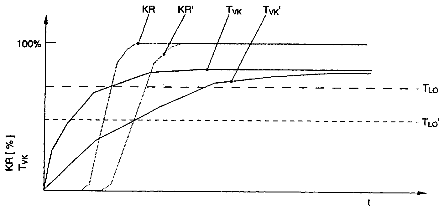
根据本发明利用了对预催化剂16的更为快速的加热过程,以便降低预催化剂的惰性金属含量。在图3中示出了基本原理。图中粗实线表示根据本发明的预催化剂温度TVK的变化曲线和细实线表示根据通常的对催化剂加热方法的预催化剂温度TVK’的变化曲线。由于根据本发明将降低预催化剂16的惰性金属含量,因而将使具有50%的碳氢化合物转换率KR的预催化剂的起始温度TLO明显地高于通常的具有高惰性金属含量的催化剂的起始温度TLO’(参见短划线)。其中转化率KR表明在催化剂上被转换的排放的分量与流入催化剂中的排放的比。本发明的具有高惰性金属含量的催化剂和具有低惰性金属含量的催化剂的相互重叠的标称的百分比转化率KR和KR’用点线示出。其中要注意的是,在绝对的非百分比表示中,由于惰性金属含量低,因而本发明的预催化剂16的最大转化率明显地低于通常的预催化剂的最大转化率。尽管本发明的系统的起始温度TLO较高,但该温度由于本发明系统的快速的加热率可以明显地早于在通常的系统中的情况得以实现。采用此方式在减少材料成本的同时可以保持相同的或甚至低于已有技术的有害物质排放。According to the invention, a more rapid heating process of the
附图标记对照表 Reference Signs Comparison Table
10 内燃机10 internal combustion engine
12 汽缸12 cylinders
14 尾气通道14 Exhaust channel
16 预催化剂16 Pre-catalyst
18 主催化剂/NOx-存储催化剂18 main catalyst/NOx-storage catalyst
20 λ探头20 lambda probe
22 度传感器22 degree sensor
24 发动机控制器24 engine controller
αZ 点火角α Z ignition angle
αEE 控制的层状喷射α EE -controlled laminar ejection
EE 单喷射EE Single Injection
EMVH 与内燃机排量有关的惰性金属含量EM VH Inert metal content in relation to internal combustion engine displacement
EMVVK 与催化剂容积有关的惰性金属含量EM VVK inert metal content in relation to catalyst volume
KR 转化率KR conversion rate
KR’ 根据已有技术的转化率KR' conversion rate based on existing technology
ME 多次喷射ME Multiple Injection
TLO 起始温度T LO onset temperature
TLO’ 根据已有技术的起始温度T LO' onset temperature according to prior art
TVK 预催化剂温度T VK pre-catalyst temperature
TVK’ 根据已有技术的预催化剂温度T VK' pre-catalyst temperature according to prior art
VH 内燃机排量V H internal combustion engine displacement
VVK 预催化剂容积V VK pre-catalyst volume
ZOT 点火上死点ZOT Ignition top dead center
Claims (38)
Applications Claiming Priority (2)
| Application Number | Priority Date | Filing Date | Title |
|---|---|---|---|
| DE10115967.6 | 2001-03-27 | ||
| DE10115967.6A DE10115967B4 (en) | 2001-03-27 | 2001-03-27 | Method and device for the aftertreatment of an exhaust gas |
Publications (2)
| Publication Number | Publication Date |
|---|---|
| CN1378037A CN1378037A (en) | 2002-11-06 |
| CN1266373C true CN1266373C (en) | 2006-07-26 |
Family
ID=7679802
Family Applications (1)
| Application Number | Title | Priority Date | Filing Date |
|---|---|---|---|
| CNB021081433A Expired - Fee Related CN1266373C (en) | 2001-03-27 | 2002-03-27 | Method and device for treating tail gas |
Country Status (2)
| Country | Link |
|---|---|
| CN (1) | CN1266373C (en) |
| DE (1) | DE10115967B4 (en) |
Families Citing this family (13)
| Publication number | Priority date | Publication date | Assignee | Title |
|---|---|---|---|---|
| JP2005214041A (en) | 2004-01-28 | 2005-08-11 | Nissan Motor Co Ltd | Control device for direct-injection spark-ignition internal combustion engine |
| WO2010129872A1 (en) | 2009-05-07 | 2010-11-11 | Scuderi Group, Llc | Air supply for components of a split-cycle engine |
| WO2011159756A1 (en) | 2010-06-18 | 2011-12-22 | Scuderi Group, Llc | Split-cycle engine with crossover passage combustion |
| US8833315B2 (en) | 2010-09-29 | 2014-09-16 | Scuderi Group, Inc. | Crossover passage sizing for split-cycle engine |
| RU2013117686A (en) | 2010-10-01 | 2014-11-20 | Скадери Груп, Инк. | V-SHAPED MOTOR CYLINDER (OPTIONS) |
| EP2668375A2 (en) | 2011-01-27 | 2013-12-04 | Scuderi Group, Inc. | Lost-motion variable valve actuation system with cam phaser |
| JP2014503752A (en) | 2011-01-27 | 2014-02-13 | スクデリ グループ インコーポレイテッド | Lost motion variable valve actuation system with valve deactivation |
| US9109468B2 (en) | 2012-01-06 | 2015-08-18 | Scuderi Group, Llc | Lost-motion variable valve actuation system |
| US9297295B2 (en) | 2013-03-15 | 2016-03-29 | Scuderi Group, Inc. | Split-cycle engines with direct injection |
| KR101786233B1 (en) * | 2015-12-07 | 2017-10-17 | 현대자동차주식회사 | Force regeneration method of GPF |
| DE102016215386A1 (en) * | 2016-08-17 | 2018-02-22 | Robert Bosch Gmbh | Method for optimizing NOx emissions in a combined exhaust aftertreatment system |
| JP6835217B2 (en) * | 2017-05-24 | 2021-02-24 | 日産自動車株式会社 | Internal combustion engine control method and control device |
| CN109372613B (en) * | 2018-12-30 | 2020-09-25 | 北京工业大学 | Pure hydrogen engine starting control method |
Family Cites Families (5)
| Publication number | Priority date | Publication date | Assignee | Title |
|---|---|---|---|---|
| DE3322439A1 (en) * | 1983-06-22 | 1985-01-03 | Bedia Maschinenfabrik Verwaltungs GmbH, 5300 Bonn | Device for reducing the pollutant contents in the exhaust gases from an internal combustion engine |
| DE3736500A1 (en) * | 1987-10-28 | 1989-05-11 | Kst Motorenversuch Gmbh Co | CATALYST SYSTEM FOR OTTO ENGINES, ESPECIALLY BOAT ENGINES, AND METHOD FOR CATALYTIC EXHAUST GAS PURIFICATION |
| DE19640161A1 (en) * | 1996-09-28 | 1998-04-02 | Volkswagen Ag | NOx emission control process |
| JP3370957B2 (en) * | 1998-09-18 | 2003-01-27 | トヨタ自動車株式会社 | Exhaust gas purification device for internal combustion engine |
| DE19918756A1 (en) * | 1999-04-24 | 2000-10-26 | Volkswagen Ag | Exhaust catalyst system includes three-way catalyst removing reductants carbon monoxide and hydrocarbons, followed by two nitrogen oxide storage catalysts optimized for operation at different temperatures |
-
2001
- 2001-03-27 DE DE10115967.6A patent/DE10115967B4/en not_active Expired - Fee Related
-
2002
- 2002-03-27 CN CNB021081433A patent/CN1266373C/en not_active Expired - Fee Related
Also Published As
| Publication number | Publication date |
|---|---|
| DE10115967A1 (en) | 2002-10-10 |
| DE10115967B4 (en) | 2014-01-09 |
| CN1378037A (en) | 2002-11-06 |
Similar Documents
| Publication | Publication Date | Title |
|---|---|---|
| CN1292157C (en) | Method for increasing exhaust gas temperature of spark-ignition, direct-injection internal combustion engine | |
| EP0974747B1 (en) | A control system for an internal combustion engine | |
| CN1298982C (en) | Detoxer unit for I.C. engine and its method | |
| US6289672B1 (en) | Exhaust gas purification device for an internal combustion engine | |
| CN1266373C (en) | Method and device for treating tail gas | |
| JP2001507103A (en) | Exhaust aftertreatment method for direct fuel injection type piston internal combustion engine | |
| CN102165171A (en) | Fuel injection control device for internal-combustion engine | |
| JP4568991B2 (en) | Engine exhaust purification device and fuel injection timing setting method | |
| JP3755494B2 (en) | Engine exhaust purification system | |
| US6370869B1 (en) | Exhaust purification device of an engine | |
| JP2004060443A (en) | Exhaust emission control device for engine | |
| CN1311151C (en) | Method and device for heating catalytic converter of gasoline direct injection internal combustion engine | |
| CN101046176A (en) | Dual combustion mode engine | |
| EP2591222B1 (en) | Fuel injection control of an internal combustion engine | |
| CN1408050A (en) | Direct Injection Internal Combustion Engines Reducing NOx Emissions | |
| JP3460503B2 (en) | Exhaust gas purification device for in-cylinder injection internal combustion engine | |
| US7114324B2 (en) | Method for operating a lean burn engine with an aftertreatment system including nonthermal plasma discharge device | |
| JP4306034B2 (en) | Engine exhaust purification system | |
| JP3536739B2 (en) | Exhaust gas purification device for internal combustion engine | |
| JP4211147B2 (en) | Fuel injection control device for diesel engine | |
| RU2434672C2 (en) | Waste gas after-treatment at reduced content of rhodium | |
| CN110030062B (en) | Method for reducing particulate emissions during cold start of an internal combustion engine | |
| JPH11294152A (en) | Compression ignition type internal combustion engine | |
| JP2000097075A (en) | Internal combustion engine | |
| JPH1047042A (en) | Exhaust gas purification system |
Legal Events
| Date | Code | Title | Description |
|---|---|---|---|
| C06 | Publication | ||
| PB01 | Publication | ||
| C10 | Entry into substantive examination | ||
| SE01 | Entry into force of request for substantive examination | ||
| C14 | Grant of patent or utility model | ||
| GR01 | Patent grant | ||
| CF01 | Termination of patent right due to non-payment of annual fee | ||
| CF01 | Termination of patent right due to non-payment of annual fee |
Granted publication date: 20060726 Termination date: 20170327 |