CN1268024C - Compressor-expander system of fuel battery - Google Patents
Compressor-expander system of fuel battery Download PDFInfo
- Publication number
- CN1268024C CN1268024C CNB2004100262034A CN200410026203A CN1268024C CN 1268024 C CN1268024 C CN 1268024C CN B2004100262034 A CNB2004100262034 A CN B2004100262034A CN 200410026203 A CN200410026203 A CN 200410026203A CN 1268024 C CN1268024 C CN 1268024C
- Authority
- CN
- China
- Prior art keywords
- fuel cell
- compressor
- expander
- decompressor
- motor
- Prior art date
- Legal status (The legal status is an assumption and is not a legal conclusion. Google has not performed a legal analysis and makes no representation as to the accuracy of the status listed.)
- Expired - Fee Related
Links
Images

Classifications
-
- Y—GENERAL TAGGING OF NEW TECHNOLOGICAL DEVELOPMENTS; GENERAL TAGGING OF CROSS-SECTIONAL TECHNOLOGIES SPANNING OVER SEVERAL SECTIONS OF THE IPC; TECHNICAL SUBJECTS COVERED BY FORMER USPC CROSS-REFERENCE ART COLLECTIONS [XRACs] AND DIGESTS
- Y02—TECHNOLOGIES OR APPLICATIONS FOR MITIGATION OR ADAPTATION AGAINST CLIMATE CHANGE
- Y02E—REDUCTION OF GREENHOUSE GAS [GHG] EMISSIONS, RELATED TO ENERGY GENERATION, TRANSMISSION OR DISTRIBUTION
- Y02E60/00—Enabling technologies; Technologies with a potential or indirect contribution to GHG emissions mitigation
- Y02E60/30—Hydrogen technology
- Y02E60/50—Fuel cells
Landscapes
- Fuel Cell (AREA)
Abstract
一种燃料电池用压缩机——膨胀机系统,该系统同时适用于低压燃料电池系统和高压燃料电池系统,它包括:用于压缩空气的一级压缩机和二级压缩机,一个向系统提供动力的电机,一个回收能量的膨胀机,它们之间通过管道、电磁阀及电磁离合器连接。通过电磁阀和电磁离合器的作用,对于低压燃料电池系统,电机驱动一级压缩机,压缩的空气直接供给燃料电池堆,从燃料电池堆排出的空气直接排入大气;对于高压燃料电池系统,空气经过一级压缩机的压缩后继续进入二级压缩机进行压缩,然后再供给燃料电池堆,从燃料电池堆排出的空气进入膨胀机膨胀做功,然后再排入大气。
A compressor-expander system for fuel cells, which is applicable to both low-pressure fuel cell systems and high-pressure fuel cell systems, and includes: a primary compressor and a secondary compressor for compressing air, one of which supplies the system with A power motor and an energy recovery expander are connected through pipelines, solenoid valves and electromagnetic clutches. Through the action of electromagnetic valve and electromagnetic clutch, for low-voltage fuel cell systems, the motor drives the primary compressor, the compressed air is directly supplied to the fuel cell stack, and the air discharged from the fuel cell stack is directly discharged into the atmosphere; for high-voltage fuel cell systems, the air After being compressed by the primary compressor, it continues to enter the secondary compressor for compression, and then it is supplied to the fuel cell stack. The air discharged from the fuel cell stack enters the expander to expand and perform work, and then is discharged into the atmosphere.
Description
技术领域technical field
本发明属于压缩机技术领域,特别涉及一种用压缩空气作为氧化剂的燃料电池用压缩机—膨胀机系统。The invention belongs to the technical field of compressors, in particular to a fuel cell compressor-expander system using compressed air as an oxidant.
背景技术Background technique
燃料电池是一个利用燃料(例如:氢)和氧化剂(例如:氧)的作用不断产生电能的电化学装置。因其效率高、对环境无污染,已经成为能源替代的关键技术。质子交换膜(PEM)燃料电池就是一种典型的氢——氧燃料电池,可应用于移动式电源,备用电源,以及电动汽车等。质子交换膜燃料电池有运行于低压和运行于高压的两种系统。低压及高压系统各有其优点。A fuel cell is an electrochemical device that uses the action of a fuel (eg hydrogen) and an oxidant (eg oxygen) to continuously generate electrical energy. Because of its high efficiency and no pollution to the environment, it has become a key technology for energy substitution. Proton exchange membrane (PEM) fuel cell is a typical hydrogen-oxygen fuel cell, which can be applied to mobile power, backup power, and electric vehicles. Proton exchange membrane fuel cells have two types of systems operating at low pressure and operating at high pressure. Both low pressure and high pressure systems have their advantages.
在燃料电池系统中,除了燃料电池本身,还需要其他辅助的装置以确保燃料电池系统的可靠连续运行,其中一个重要的辅件就是向燃料电池提供压缩空气的压缩机—膨胀机系统。对于低压燃料电池系统,由于从燃料电池排出的空气的压力较低,仅用压缩机就可以完成;而对于高压燃料电池系统,由于燃料电池排出的空气具有相当高的压力,为了提高燃料电池的系统效率,系统中往往采用膨胀机来回收能量。燃料电池系统的压力是随工况发生变化的,而膨胀机的膨胀比是不变的,当膨胀机的进口压力低于设计压力时,在膨胀机中就会产生过膨胀,造成额外功耗。In the fuel cell system, in addition to the fuel cell itself, other auxiliary devices are needed to ensure the reliable and continuous operation of the fuel cell system. One of the important auxiliary parts is the compressor-expander system that provides compressed air to the fuel cell. For low-pressure fuel cell systems, due to the low pressure of the air discharged from the fuel cell, only a compressor can be used; while for a high-pressure fuel cell system, since the air discharged from the fuel cell has a relatively high pressure, in order to improve the fuel cell System efficiency, expanders are often used in the system to recover energy. The pressure of the fuel cell system changes with the working conditions, but the expansion ratio of the expander is constant. When the inlet pressure of the expander is lower than the design pressure, overexpansion will occur in the expander, resulting in additional power consumption .
发明内容Contents of the invention
本发明的目的在于提供一种结构简单,且膨胀机可根据不同情况选择的既适用于低压又适用于高压燃料电池系统的压缩机—膨胀机系统。The purpose of the present invention is to provide a compressor-expander system suitable for both low-pressure and high-pressure fuel cell systems, which has a simple structure, and the expander can be selected according to different situations.
为达到上述目的,本发明采用的技术方案是:包括电机以及与电机的输出轴相连接的一级压缩机,一级压缩机的出口通过管道与燃料电池堆的入口相连通,其特点是,燃料电池堆的出口管道上还并联有电磁阀和膨胀机电磁阀,膨胀机通过管道和膨胀机电磁阀与燃料电池堆相连通,一级压缩机与燃料电池堆相连接的管道上还设置有电磁阀,一级压缩机的出口还可通过二级压缩机电磁阀与二级压缩机的入口相连通,二级压缩机的出口通过单向阀与燃料电池堆的入口相连通,二级压缩机又通过二级压缩机电磁离合器和传动装置与电机的输出轴相连,电机的另一输出轴通过膨胀机离合器与膨胀机相连。In order to achieve the above object, the technical solution adopted by the present invention is: comprising a motor and a first-stage compressor connected to the output shaft of the motor, the outlet of the first-stage compressor communicates with the inlet of the fuel cell stack through a pipeline, and its characteristics are: The outlet pipeline of the fuel cell stack is also connected in parallel with a solenoid valve and an expander solenoid valve. The expander communicates with the fuel cell stack through the pipeline and the expander solenoid valve. The pipeline connecting the primary compressor and the fuel cell stack is also provided with a Solenoid valve, the outlet of the primary compressor can also be connected with the inlet of the secondary compressor through the solenoid valve of the secondary compressor, the outlet of the secondary compressor is connected with the inlet of the fuel cell stack through the check valve, and the secondary compressor The machine is connected with the output shaft of the motor through the electromagnetic clutch and transmission device of the secondary compressor, and the other output shaft of the motor is connected with the expander through the expander clutch.
本发明的另一特点是:电机还可通过二级压缩机电磁离合器直接与二级压缩机相连接,电机的另一输出轴通过传动装置与一级压缩机和膨胀机相连接,在膨胀机与传动装置7之间设置有膨胀机电磁离合器;膨胀机包括由动涡盘和静涡盘组成的膨胀腔,在静涡盘上开设有与膨胀腔相连通的轴向气体通道和与膨胀机的进气口相连通的径向气体通道,静涡盘的背面径向气体通道上还套装有弹簧和活塞,活塞上还开设有可与轴向气体通道相连通的气体通道。Another feature of the present invention is: the motor can also be directly connected with the second-stage compressor through the electromagnetic clutch of the second-stage compressor, and the other output shaft of the motor is connected with the first-stage compressor and the expander through a transmission device. An expander electromagnetic clutch is arranged between the transmission device 7; the expander includes an expansion chamber composed of a movable scroll and a fixed scroll, and an axial gas passage communicated with the expansion chamber is opened on the fixed scroll and connected with the expander. The radial gas channel connected to the air inlet of the fixed scroll is also equipped with a spring and a piston on the radial gas channel on the back of the static scroll, and a gas channel that can communicate with the axial gas channel is opened on the piston.
由于本发明的电机通过电磁离合器与二级压缩机和膨胀机相连接,同时又通过管道上的电磁阀可选择的将一级压缩机与二级压缩机及膨胀机相连通,即适用于低压又适用于高压燃料电池系统,对于低压燃料电池系统,电机驱动一级压缩机,经一级压缩机压缩的空气进入燃料电池堆,然后排入大气;对于高压燃料电池系统,空气经过一级压缩机的压缩后继续进入二级压缩机进行压缩,然后再供给燃料电池堆,从燃料电池堆排出的空气进入膨胀机膨胀做功,然后再排入大气。Because the motor of the present invention is connected with the secondary compressor and the expander through the electromagnetic clutch, and at the same time, the electromagnetic valve on the pipeline can selectively connect the primary compressor with the secondary compressor and the expander, that is, it is suitable for low-pressure It is also suitable for high-voltage fuel cell systems. For low-voltage fuel cell systems, the motor drives a first-stage compressor, and the air compressed by the first-stage compressor enters the fuel cell stack and then is discharged into the atmosphere; for high-voltage fuel cell systems, the air is compressed by the first stage. After being compressed by the compressor, it continues to enter the secondary compressor for compression, and then it is supplied to the fuel cell stack. The air discharged from the fuel cell stack enters the expander to expand and perform work, and then is discharged into the atmosphere.
附图说明Description of drawings
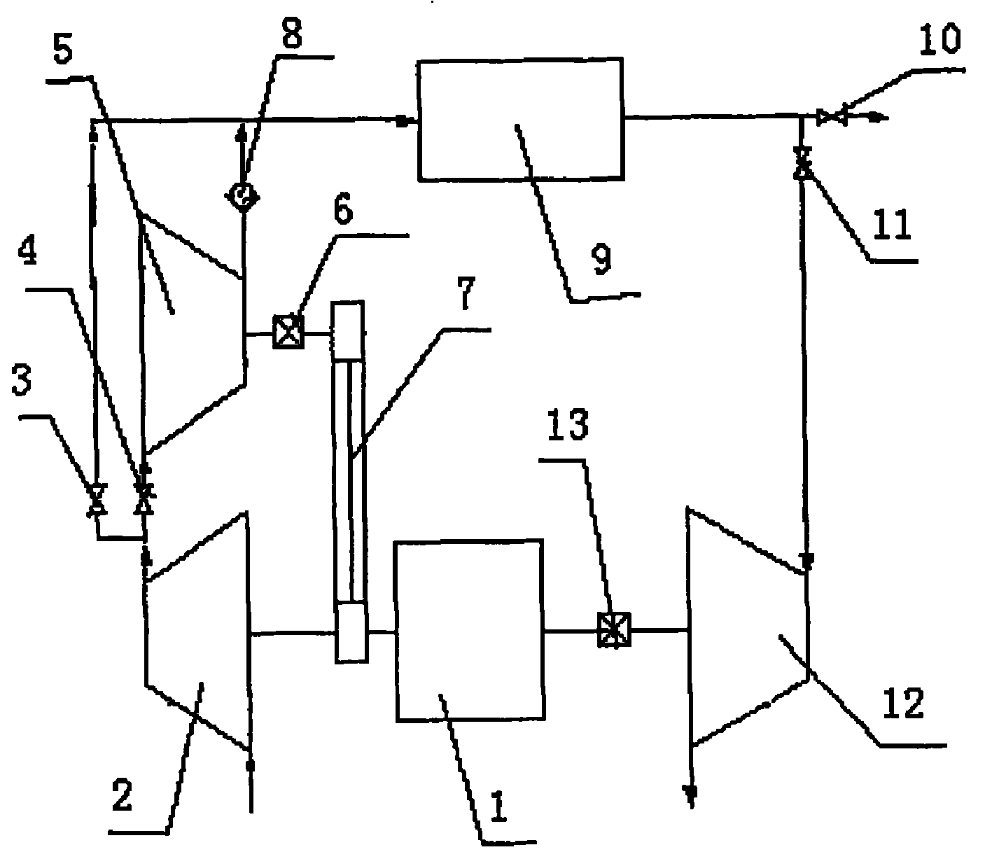
图1是本发明的整体结构示意图,其中图1(a)是本发明实施例1的结构示意图,图1(b)是本发明实施例2的结构示意图;Fig. 1 is the overall structural representation of the present invention, wherein Fig. 1 (a) is the structural representation of embodiment 1 of the present invention, Fig. 1 (b) is the structural representation of embodiment 2 of the present invention;
图2是本发明膨胀机12的结构示意图。Fig. 2 is a schematic structural view of the expander 12 of the present invention.
具体实施方式Detailed ways
下面结合附图对本发明的结构原理和工作原理作进一步详细说明。The structural principle and working principle of the present invention will be further described in detail below in conjunction with the accompanying drawings.
实施例1,参见图1(a),图2,本发明包括电机1以及与电机1的输出轴相连接的一级压缩机2,电机1的输出轴还通过二级压缩机电磁离合器6和传动装置7与二级压缩机5相连,电机1的另一输出轴通过膨胀机离合器13与膨胀机12相连,膨胀机12包括由动涡盘15和静涡盘16组成的膨胀腔14,在静涡盘16上开设有与膨胀腔14相连通的轴向气体通道22和与膨胀机12的进气口21相连通的径向气体通道20,静涡盘16的背面还套装有弹簧17和活塞18,活塞18与径向气体通道20相连通,同时活塞18上还开设有可与轴向气体通道22相连通的气体通道19,一级压缩机2的出口分别通过并联有电磁阀3、二级压缩机电磁阀4与燃料电池9及二级压缩机5的入口相连通,二级压缩机5的出口通过单向阀8与燃料电池堆9的入口相连通,燃料电池堆9的出口管道上还并联有电磁阀10和膨胀机电磁阀11,膨胀机12通过管道和膨胀机电磁阀11与燃料电池堆9相连通。在低压燃料电池系统中,本发明的工作过程为:电机1驱动一级压缩机2,二级压缩机电磁离合器6及膨胀机电磁离合器13断开,即二级压缩机5及膨胀机12不工作。二级压缩机电磁阀4断开,电磁阀3接通,空气经一级压缩机2的压缩后经电磁阀3后直接进入低压燃料电池堆9。此时电磁阀10接通,膨胀机电磁阀11断开,所以从燃料电池堆9排出的空气经电磁阀10后排入大气。在高压燃料电池系统中,本发明的工作过程为:电机1直接驱动一级压缩机2,通过传动装置7驱动二级压缩机5。二级压缩机电磁离合器6和膨胀机电磁离合器13接通,电磁阀3和电磁阀10断开,二级压缩机电磁阀4和膨胀机电磁阀11接通,空气经一级压缩机2压缩后经二级压缩机电磁阀4进入二级压缩机5,然后经单向阀8后进入高压燃料电池堆9,从燃料电池堆9排出的空气经膨胀机电磁阀11后进入膨胀机12膨胀作功,然后排入大气。膨胀产生的功传递给一级压缩机,达到回收功的目的。膨胀机12内的活塞18受进气压力和弹簧17力的双向作用,当膨胀机12进气孔21的实际进气压力大于或者等于膨胀机12的设计进气压力时,由于气体压力大于弹簧17的压力,此气体压力通过径向气体通道20推动活塞18,使活塞18上的气体通道19不能与静涡盘16上的轴向通道22联通,气体在膨胀机12中的膨胀过程一直持续到设计的排气过程,当膨胀机12的实际进气压力小于其设计进气压力时,作用在活塞18上的气体力减小,活塞则在弹簧17的作用下向下移动,此时静涡盘16上的轴向通道22与活塞18上的径向气体通道20联通,使膨胀机12排气过程提前,从而避免了过膨胀所带来的额外功耗。Embodiment 1, referring to Fig. 1 (a), Fig. 2, the present invention comprises motor 1 and the primary compressor 2 that is connected with the output shaft of motor 1, the output shaft of motor 1 also passes through secondary compressor electromagnetic clutch 6 and The transmission device 7 is connected with the secondary compressor 5, and the other output shaft of the motor 1 is connected with the expander 12 through the expander clutch 13. The expander 12 includes an
实施例2:参见图1(b),图2,本发明的电机1通过二级压缩机电磁离合器6直接与二级压缩机5相连接,电机1的另一输出轴通过传动装置7与一级压缩机2和膨胀机12相连接,在膨胀机12与传动装置7之间设置有膨胀机电磁离合器13,其它连接关系及工作原理同实施例1。Embodiment 2: referring to Fig. 1 (b), Fig. 2, motor 1 of the present invention is directly connected with secondary compressor 5 by secondary compressor electromagnetic clutch 6, and another output shaft of motor 1 is connected with a transmission device 7 The first-stage compressor 2 is connected to the expander 12, and an expander electromagnetic clutch 13 is arranged between the expander 12 and the transmission device 7. The other connections and working principles are the same as those in Embodiment 1.
本发明通过系统中电磁阀及电磁离合器的作用,对于低压燃料电池系统,电机驱动一级压缩机,经一级压缩机压缩的空气进入燃料电池堆,然后排入大气;对于高压燃料电池系统,空气经过一级压缩机的压缩后继续进入二级压缩机进行压缩,然后再供给燃料电池堆,从燃料电池堆排出的空气进入膨胀机膨胀做功,然后再排入大气,即适用于低压又适用于高压燃料电池系统。In the present invention, through the action of the electromagnetic valve and the electromagnetic clutch in the system, for the low-voltage fuel cell system, the motor drives the first-stage compressor, and the air compressed by the first-stage compressor enters the fuel cell stack, and then is discharged into the atmosphere; for the high-voltage fuel cell system, After being compressed by the primary compressor, the air continues to enter the secondary compressor for compression, and then is supplied to the fuel cell stack. The air discharged from the fuel cell stack enters the expander to expand and perform work, and then is discharged into the atmosphere, which is suitable for both low pressure and in high-voltage fuel cell systems.
Claims (2)
Priority Applications (1)
| Application Number | Priority Date | Filing Date | Title |
|---|---|---|---|
| CNB2004100262034A CN1268024C (en) | 2004-06-03 | 2004-06-03 | Compressor-expander system of fuel battery |
Applications Claiming Priority (1)
| Application Number | Priority Date | Filing Date | Title |
|---|---|---|---|
| CNB2004100262034A CN1268024C (en) | 2004-06-03 | 2004-06-03 | Compressor-expander system of fuel battery |
Publications (2)
| Publication Number | Publication Date |
|---|---|
| CN1585177A CN1585177A (en) | 2005-02-23 |
| CN1268024C true CN1268024C (en) | 2006-08-02 |
Family
ID=34601247
Family Applications (1)
| Application Number | Title | Priority Date | Filing Date |
|---|---|---|---|
| CNB2004100262034A Expired - Fee Related CN1268024C (en) | 2004-06-03 | 2004-06-03 | Compressor-expander system of fuel battery |
Country Status (1)
| Country | Link |
|---|---|
| CN (1) | CN1268024C (en) |
Families Citing this family (10)
| Publication number | Priority date | Publication date | Assignee | Title |
|---|---|---|---|---|
| US8795907B2 (en) * | 2010-02-19 | 2014-08-05 | GM Global Technology Operations LLC | Compressor system with a freewheeling expander |
| CN102996181A (en) * | 2011-09-08 | 2013-03-27 | 上海汉钟精机股份有限公司 | Open-type double screw decompressor |
| KR101985023B1 (en) * | 2012-12-26 | 2019-05-31 | 현대모비스 주식회사 | Air supply device using compressed stored hydrogen and air supply system including the same |
| CN109167087B (en) * | 2018-09-17 | 2022-05-13 | 新乡市特美特热控技术股份有限公司 | A fuel cell air management system |
| CN110649287B (en) * | 2019-09-30 | 2021-03-16 | 潍柴动力股份有限公司 | Fuel cell engine system, gas supply system thereof and control method |
| CN111911254B (en) * | 2020-06-28 | 2022-03-18 | 东风汽车集团有限公司 | Energy recovery device of fuel cell system |
| CN111952635B (en) * | 2020-08-18 | 2022-05-13 | 东风汽车集团有限公司 | Adjustable air supply device for fuel cell system |
| CN111963464A (en) * | 2020-08-27 | 2020-11-20 | 中船重工(重庆)西南装备研究院有限公司 | Self-adaptive air compressor for hydrogen fuel cell |
| CN114122454A (en) * | 2021-11-25 | 2022-03-01 | 上海捷氢科技股份有限公司 | Fuel cell and air supply system thereof |
| CN115559922A (en) * | 2022-10-14 | 2023-01-03 | 势加透博(成都)科技有限公司 | Compressor |
-
2004
- 2004-06-03 CN CNB2004100262034A patent/CN1268024C/en not_active Expired - Fee Related
Also Published As
| Publication number | Publication date |
|---|---|
| CN1585177A (en) | 2005-02-23 |
Similar Documents
| Publication | Publication Date | Title |
|---|---|---|
| US6365290B1 (en) | High-efficiency fuel cell system | |
| CN106907239B (en) | A kind of power circulation system of hydrogen gas turbine and hydrogen fuel cell combination | |
| CN1268024C (en) | Compressor-expander system of fuel battery | |
| CN107780989B (en) | A compressed air power storage system | |
| CN215644595U (en) | Compressed air system for hydrogen fuel cell | |
| US20190363381A1 (en) | Device For The Air Supply Of A Fuel Cell, Preferentially Of A Fuel Cell Operated With Hydrogen | |
| CN107514294B (en) | A combined compressed air energy storage system and its control method | |
| CN107634245A (en) | A kind of hydrogen cell automobile pressure energy drives hydrogen gas circulating pump device | |
| CN112382779A (en) | Fuel cell device with energy recovery system | |
| CN115117394A (en) | Air compressor arrangement and fuel cell arrangement comprising an air compressor arrangement | |
| US7615304B2 (en) | SOFC systems to power a liquid or gas fuel pumping station | |
| CN114792826A (en) | An air pressurization system and method utilizing high pressure hydrogen | |
| CN117662416B (en) | Multistage compressed air energy storage system and power station | |
| CN1841829B (en) | Fuel battery apparatus possessing recirculated work fuel | |
| CN207526536U (en) | A kind of combined compressed air energy-storage system | |
| CN217440320U (en) | Cooling device of fuel cell air compressor | |
| CN117553018A (en) | Multi-stage series energy recovery air compressor unit | |
| CN115539156B (en) | A natural gas station integrated energy system with constant pressure compressed air energy storage | |
| CN216922237U (en) | Air medium's heat pump electric storage system | |
| CN117889094A (en) | Compressor unit of small-flow compressed carbon dioxide energy storage system and operation method | |
| CN214705992U (en) | Air compressor unit for hydrogen fuel cell | |
| CN216110878U (en) | Fuel cell and compressed air energy storage coupled power generation system | |
| CN116190712A (en) | A high-pressure air delivery system for fuel cells in a low-pressure environment | |
| CN214997831U (en) | Natural air pressure difference power generation and cold energy utilization system | |
| WO2024033042A3 (en) | Fuel cell system and vehicle, in particular utility vehicle |
Legal Events
| Date | Code | Title | Description |
|---|---|---|---|
| C06 | Publication | ||
| PB01 | Publication | ||
| C10 | Entry into substantive examination | ||
| SE01 | Entry into force of request for substantive examination | ||
| C14 | Grant of patent or utility model | ||
| GR01 | Patent grant | ||
| C17 | Cessation of patent right | ||
| CF01 | Termination of patent right due to non-payment of annual fee |
Granted publication date: 20060802 Termination date: 20100603 |