CN1274103C - Optical ring net for burst data communication - Google Patents
Optical ring net for burst data communication Download PDFInfo
- Publication number
- CN1274103C CN1274103C CNB031450806A CN03145080A CN1274103C CN 1274103 C CN1274103 C CN 1274103C CN B031450806 A CNB031450806 A CN B031450806A CN 03145080 A CN03145080 A CN 03145080A CN 1274103 C CN1274103 C CN 1274103C
- Authority
- CN
- China
- Prior art keywords
- channel
- burst
- data
- optical
- channels
- Prior art date
- Legal status (The legal status is an assumption and is not a legal conclusion. Google has not performed a legal analysis and makes no representation as to the accuracy of the status listed.)
- Expired - Fee Related
Links
Images


Classifications
-
- H—ELECTRICITY
- H04—ELECTRIC COMMUNICATION TECHNIQUE
- H04L—TRANSMISSION OF DIGITAL INFORMATION, e.g. TELEGRAPHIC COMMUNICATION
- H04L12/00—Data switching networks
- H04L12/28—Data switching networks characterised by path configuration, e.g. LAN [Local Area Networks] or WAN [Wide Area Networks]
- H04L12/42—Loop networks
-
- H—ELECTRICITY
- H04—ELECTRIC COMMUNICATION TECHNIQUE
- H04Q—SELECTING
- H04Q11/00—Selecting arrangements for multiplex systems
- H04Q11/0001—Selecting arrangements for multiplex systems using optical switching
- H04Q11/0062—Network aspects
- H04Q11/0066—Provisions for optical burst or packet networks
-
- H—ELECTRICITY
- H04—ELECTRIC COMMUNICATION TECHNIQUE
- H04Q—SELECTING
- H04Q11/00—Selecting arrangements for multiplex systems
- H04Q11/0001—Selecting arrangements for multiplex systems using optical switching
- H04Q11/0062—Network aspects
- H04Q2011/009—Topology aspects
- H04Q2011/0092—Ring
Landscapes
- Engineering & Computer Science (AREA)
- Computer Networks & Wireless Communication (AREA)
- Signal Processing (AREA)
- Optical Communication System (AREA)
- Small-Scale Networks (AREA)
- Data Exchanges In Wide-Area Networks (AREA)
- Use Of Switch Circuits For Exchanges And Methods Of Control Of Multiplex Exchanges (AREA)
Abstract
提出了用于突发数据通信的光环形网,该光环形网具有通过光纤链路相互连接的多个核心节点。每一个核心节点包括:解复用器,用于根据波长将接收到的光信号解复用为多个信道;分插部分,用于根据控制信号从多个信道中分出选择的信道;复用器,用于复用和输出从分插部分接收到的多个信道;设置在解复用器和分插部分之间的分路部分,用于从每一个信道中分路信道部分;以及控制器,用于识别使用每一个信道调制的帧的目的地,并且向分插部分输出用于分出选择的信道的控制信号。

An optical ring network with multiple core nodes interconnected by fiber optic links is proposed for bursty data communication. Each core node includes: a demultiplexer, which is used to demultiplex the received optical signal into multiple channels according to the wavelength; an add-drop part, which is used to separate the selected channel from multiple channels according to the control signal; A multiplexer for multiplexing and outputting a plurality of channels received from the add/drop section; a branching section provided between the demultiplexer and the add/drop section for branching a channel portion from each channel; and A controller for identifying a destination of the frame modulated using each channel, and outputting a control signal for dropping the selected channel to the add/drop section.
Description
技术领域technical field
本发明涉及一种光环形网,并且特别涉及一种使用波分复用技术的光环形网。The present invention relates to an optical ring network, and particularly relates to an optical ring network using wavelength division multiplexing technology.
背景技术Background technique
最近,已经意识到必需配置所有的光网络以便处理数据流量的巨大增长。出于这个目的,已经提出了用于配置光网络的各种解决方案。此外,由于在开发光传输系统和光路由设备上的相当大的努力,因此在市场上可以得到各种产品。基于波分复用(WDM)的光环形网是一种吸引了相当大的注意力的网络技术。这是由于它的易于配置、交换恢复、初始成本的降低等。世界上的多个国家已经采用了这样的光环形网。Recently, it has been realized that all optical networks must be configured in order to handle the huge increase in data traffic. For this purpose, various solutions for configuring optical networks have been proposed. Furthermore, due to considerable efforts in developing optical transmission systems and optical routing equipment, various products are available in the market. Optical ring network based on wavelength division multiplexing (WDM) is a network technology that has attracted considerable attention. This is due to its ease of configuration, exchange recovery, reduction in initial cost, etc. Many countries in the world have adopted such an optical ring network.
配置这样的光环形网以便使用多个信道执行节点之间的通信。更具体地说,将节点之间的通信连接所需要的一个或者多个信道分配给一对节点,并且通过信道来执行双向通信。然而,这样的网络在它的灵活性特别是处理数据流量突发上存在严重的缺陷。此外,它们在网络的总的带宽性能上存在显著的降低。这些缺陷是由于配置的光环形网通过信道来路由通信,并且因为预先设置了这些信道。Such an optical ring network is configured so as to perform communication between nodes using a plurality of channels. More specifically, one or more channels required for communication connection between nodes are assigned to a pair of nodes, and bidirectional communication is performed through the channels. However, such a network has serious drawbacks in its flexibility, especially in handling bursts of data traffic. Furthermore, they present a significant decrease in the overall bandwidth performance of the network. These deficiencies are due to the optical ring being configured to route traffic through channels, and because these channels are pre-set.
为了克服这些缺点,工程师们已经在研究和开发基于光分组交换(OPS)和光突发交换(OBS)的光路由器上,取得了显著的进展。然而,在实现OPS和OBS技术时还存在许多问题。由于OPS或者OBS执行分组或者突发交换,分组或者突发不仅应该在网络中的每个节点免于碰撞,而且应该能够以非常快的速度交换。为了解决后一个问题(即由诸如光缓冲器的光器件导致的问题),首先应该解决高速光交换等。由于这个原因,正在寻求使用突发延迟线,波长转换器等的可选择的解决方案,所有这些方案基于光纤。然而,这样的方案还没有产生满意的效果,而且,这些方案还没有满足经济上的考虑,而经济上的考虑通常会花费相当长的时间。In order to overcome these shortcomings, engineers have made remarkable progress in the research and development of optical routers based on Optical Packet Switching (OPS) and Optical Burst Switching (OBS). However, there are still many problems in implementing OPS and OBS technologies. Since OPS or OBS performs packet or burst switching, packets or bursts should not only be free from collisions at every node in the network, but should also be able to be switched at a very fast speed. In order to solve the latter problem (ie, the problem caused by optical devices such as optical buffers), high-speed optical switching and the like should be solved first. For this reason, alternative solutions using burst delay lines, wavelength converters, etc., all based on optical fiber, are being sought. However, such solutions have not produced satisfactory results, and moreover, they have not satisfied economical considerations, which usually take a considerable time.
简而言之,采用WDM并且在其中使用信道来设置光路径的传统的光环形网适合于大容量静态数据的产生,而不适合于突发数据的传输。而且,传统的网络不能有效地、没有浪费地使用大容量的带宽。此外,在基于OPS和OBS的提出的光路由器网络中,为了弥补前述的缺陷,绝对需要诸如光缓冲器、波长转换器的器件来降低数据间的碰撞。然而,传统的技术在实现这些器件时,特别是从经济的观点上,还会遇到许多问题和困难。In short, the traditional optical ring network that adopts WDM and uses channels to set up optical paths in it is suitable for the generation of large-capacity static data, but not for the transmission of burst data. Moreover, conventional networks cannot efficiently use large amounts of bandwidth without wasting it. In addition, in the proposed optical router network based on OPS and OBS, in order to compensate for the aforementioned defects, devices such as optical buffers and wavelength converters are absolutely required to reduce collisions between data. However, conventional techniques still encounter many problems and difficulties in realizing these devices, especially from an economical point of view.
发明内容Contents of the invention
本发明通过提供适合于传输大容量的突发数据、并且从技术和经济的观点来看具有相当好的实现能力的光环形网,减少或者克服许多的上述限制。The present invention reduces or overcomes many of the above-mentioned limitations by providing an optical ring network suitable for transmitting large-capacity burst data and having relatively good implementation capabilities from a technical and economical point of view.
本发明还提供一种能够改进网络的带宽性能的光环形网。The invention also provides an optical ring network capable of improving the bandwidth performance of the network.
依据本发明的原则的说明性的实施例,提供了一种用于突发数据通信的光环形网,该光环形网包括:通过光纤链路相互连接的多个核心节点,其中每个核心节点包括:解复用器,用于将接收到的光信号解复用为多个信道;分插部分,用于从多个信道中分出选择的信道,输出所分出的信道来进行光电转换,并且使其他的未选择信道通过以使其去往复用器;复用器,用于复用通过分插部分输入的未选择信道,并将其输出到其他核心节点;分路部分,用于从来自解复用器的多个信道的各个信道中分路信道部分;以及控制器,用于使用分路的信道部分识别在每个信道上调制的帧的目的地,并且将用于分出选择的信道的控制信号输出到分插部分。所述光环形网还包括提供给每一个核心节点的入口节点,该入口节点包括:与多个服务设备连接的接口部分,用于识别从服务设备接收到的分组数据的目的地;具有依据目的地细分的多个缓冲器的突发组装器,用于以预定长度绑定在每个缓冲器中存储的分组数据以便创建突发数据;第一电交换机,用于依据目的地,将从接口部分接收到的分组数据输出到突发组装器的对应的缓冲器;头添加部分,用于绑定接收到的突发数据和表示目的地的头数据以便创建帧;第二电交换机,用于依据控制器的控制信号,输出在突发组装器的对应的缓冲器中存储的突发数据;以及光发射部分,用于允许将从头添加部分接收到的,由帧调制的信道输出到每一个核心节点的分插部分。所述光环形网还包括提供给每一个核心节点的出口节点,该出口节点包括:光接收部分,用于对从每一个核心节点的分插部分接收到的信道中的帧进行光电转换并输出其;突发拆分器,用于从每一个帧中移出头数据以便将突发数据拆分为分组数据;IP分组转发部分,用于识别从突发拆分器中接收到的分组数据的IP地址;与多个服务设备连接的多个接口卡;以及电交换机,用于允许依据IP地址,将从IP分组转发部分接收到的分组数据输出到对应的接口卡。According to an illustrative embodiment of the principle of the present invention, an optical ring network for burst data communication is provided, the optical ring network includes: a plurality of core nodes interconnected by optical fiber links, wherein each core node Including: a demultiplexer, which is used to demultiplex the received optical signal into multiple channels; an add/drop part, which is used to separate selected channels from multiple channels, and output the separated channels for photoelectric conversion , and pass other unselected channels to make it go to the multiplexer; the multiplexer is used to multiplex the unselected channels input through the add/drop part and output them to other core nodes; the splitter part is used for Splitting channel portions from each of the plurality of channels from the demultiplexer; and a controller for identifying, using the split channel portions, the destination of frames modulated on each channel and to be used for dropping The control signal of the selected channel is output to the add/drop section. The optical ring network also includes an ingress node provided to each core node, the ingress node includes: an interface part connected with a plurality of service devices, used to identify a destination of packet data received from the service devices; A burst assembler of a plurality of subdivided buffers for binding packet data stored in each buffer with a predetermined length so as to create burst data; a first electrical switch for, depending on the destination, from The packet data received by the interface part is output to the corresponding buffer of the burst assembler; the header adding part is used to bind the received burst data and the header data representing the destination so as to create a frame; the second electric switch uses Outputting the burst data stored in the corresponding buffer of the burst assembler according to the control signal of the controller; Add-drop part of a core node. The optical ring network also includes an egress node provided to each core node, and the egress node includes: an optical receiving part for photoelectrically converting and outputting a frame in a channel received from the add/drop part of each core node It; a burst splitter, used to remove the header data from each frame so that the burst data is split into packet data; the IP packet forwarding part is used to identify the part of the packet data received from the burst splitter IP addresses; a plurality of interface cards connected to a plurality of service devices; and an electrical switch for allowing packet data received from the IP packet forwarding section to be output to corresponding interface cards according to the IP addresses.
附图说明Description of drawings
从结合附图采用的以下详细描述中,本发明将更加明显,The present invention will become more apparent from the following detailed description taken in conjunction with the accompanying drawings,
图1显示依据本发明的优选实施例的用于突发数据通信的光环形网的示意配置;FIG. 1 shows a schematic configuration of an optical ring network for burst data communication according to a preferred embodiment of the present invention;
图2显示图1所示的任一个核心节点的示意配置;Figure 2 shows a schematic configuration of any one of the core nodes shown in Figure 1;
图3显示图2所示的入口节点的示意配置;Figure 3 shows a schematic configuration of the entry node shown in Figure 2;
图4显示图2所示的出口节点的示意配置;Figure 4 shows a schematic configuration of the egress node shown in Figure 2;
图5是显示图1所示的一个核心节点A的信道的插入或者分出过程;Fig. 5 shows the process of adding or dropping a channel of a core node A shown in Fig. 1;
图6显示与图1所示的一个核心节点A相关的时隙。FIG. 6 shows the time slots associated with one core node A shown in FIG. 1 .
具体实施方式Detailed ways
在本发明的以下描述中,出于解释而非限定性的目的,阐明了诸如特定结构、接口、技术等具体细节,以便提供本发明的完全理解。然而,对本领域的技术人员将显而易见的是,可以在不按照这些具体细节的其他实施例中实施本发明。而且,将会意识到出于解释的目的,简化了图形的某些方面,以及用于本发明的整个系统环境将包括所有那些不需要显示于此的许多已知的功能和配置。在图形中,即使在不同的图形中表示它们,也要使用相同的参考数字来表示相同或者相似的元件。In the following description of the present invention, for purposes of explanation and not limitation, specific details are set forth, such as specific structures, interfaces, techniques, etc., in order to provide a thorough understanding of the present invention. It will be apparent, however, to one skilled in the art that the present invention may be practiced in other embodiments that do not follow these specific details. Also, it will be appreciated that certain aspects of the drawings have been simplified for explanatory purposes, and that the overall system environment for the present invention will include all of the many known functions and configurations that need not be shown here. In the drawings, the same reference numerals are used to designate the same or similar elements even if they are represented in different drawings.
图1显示依据本发明的优选实施例的用于突发数据通信的光环形网的示意配置。在图1中,环形网包括使用前向和后向光纤链路500和600,或者工作和保护光纤链路连接的多个核心节点100。核心节点100还与多个边缘节点300连接,其中,它们一对一地对应连接。至少一个由多个信道组成的光信号在核心节点100之间传输,并且该光信号经过了波分复用(WDM)。同时,至少一个独立的信道在核心节点中的任何一个和边缘节点中的对应的一个之间传输。环形网使用突发数据单元执行通信,其中,依据目的地来分类从多个服务设备中收集到的分组数据。按照预定的数据长度来绑定已分类的数据,并且传输已绑定的数据。也就是说,在每个信道上传输的帧包括:由具有相同目的地和服务质量(QoS)的分组数据组成的突发数据;指示帧的目的地的头(header)数据。在每一个核心节点100中,从接收到的每一个信道上调制的帧中识别头数据,并且在此基础上,执行交换。更具体地说,当每一个核心节点100与识别的头数据指示的目的地匹配时,会导致调制的帧被分出。然而,当不匹配时,会使调制的帧被传送到下一个核心节点100。Fig. 1 shows a schematic configuration of an optical ring network for burst data communication according to a preferred embodiment of the present invention. In FIG. 1, the ring network includes a plurality of
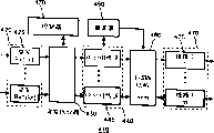
图2显示图1所示的任一个核心节点的示意配置。在图2中,核心节点100包括各种器件,将这些器件分类为前向光纤链路550的器件110和后向光纤链路600的器件200。在正常状态下,前向和后向光纤链路550和600都要被使用。然而,在不正常或者链路故障的状态,与前向光纤链路550相比,更多地使用后向光纤链路600。出于方便而非限定的目的,以下将对后向光纤链路600的器件200进行描述。FIG. 2 shows a schematic configuration of any one of the core nodes shown in FIG. 1 . In FIG. 2 , the
核心节点100包括:解复用器120、分插部分130、复用器140、分路部分150、光接收器160、以及控制器170。The
解复用器120按照信道(或者按照波长)执行解复用,并且输出从另一相邻核心节点输入的光信号。解复用器120使用:例如具有一个输入接线端和N个输出接线端的1×N阵列波导光栅。The
分插部分130包括与解复用器120的输出接线端一一对应连接的多个(N)2×2光开关135。光开关135依据控制器170的控制信号,执行交换操作。同时,光开关135用于:或者将从解复用器120接收到的信道分出到为对应的边缘节点300配置的出口节点410,或者将它们传送到复用器140。此外,光开关135用于插入从为对应的边缘节点300配置的入口节点310输入的信道,并且将插入的信道输出到复用器140。The add/
复用器140使从分插部分输入的多个信道被复用以及被输出。The
复用器140可以使用:例如,具有N个输出接线端和一个输出接线端的N×1阵列波导光栅。像一般的光学设备一样,阵列波导光栅具有可逆的能力,以致于可以使用它作为复用器或者解复用器。The
分路部分150包括N个1×2抽头耦合器155,这些耦合器与解复用器120的输出接线端一一对应地连接。将分路部分150定位在解复用器120和分插部分130之间,该分路部分从每个信道分路信道部分。举例来说,对于输入抽头耦合器155的每一个信道,分路部分150将具有每个信道的整个能量的10%的已分路的信道部分提供给光接收器160,并且将具有每个信道的整个能量的90%的其他已分路的信道部分提供给光开关135。The branching
光接收器160包括多个(N)光电二极管,这些光电二极管与N个光耦合器一一对应地连接。光接收器160执行已分路信道的光电转换,并且输出这些结果。The
控制器170解调经过了光电转换的信道上的帧,提取每个帧的头数据,并且识别对应于头数据的目的地。此外,控制器检测其目的地与分插部分130匹配的帧,并且向分插部分130输出用于有选择地分出检测到的帧的控制信号。因此,控制器将控制信号输出到光开关135,其中,具有在检测到的帧之中已调制的帧的信道输入到该光开关。光开关135执行开关过程,以便相对于出口节点410分出相关的信道。此外,控制器170通过识别从入口节点310创建的帧的目的地、QOS等,确定用于传输已调制的帧的信道,以及用于传输这些信道的时刻。The
每个边缘节点300包括入口节点310和出口节点410。Each
图3显示图2所示的入口节点的示意配置。在图3中,入口节点310包括:接口部分320、查询表330、第一电交换机(switch)340、突发组装器350、第二电交换机360、头添加部分370、以及光发射部分380。FIG. 3 shows a schematic configuration of the entry node shown in FIG. 2 . In FIG. 3 , the
接口部分320包括多个(M)接口卡325,接口卡中的每一个与每一个服务设备连接。该服务设备可以是IP路由器、以太网交换机、SONET设备等。接口部分320向不同的服务形式提供接口。它还识别目的地、QOS等,从而按照这样的方式,提取每次从几个位置接收到的分组数据的控制信号,例如IP数据的分组头。The
查询表330具有依据目的地和QOS存储的突发组装器350的缓冲器数量。The look-up table 330 has the buffer numbers of the
第一电交换机340不仅参考在接口部分320识别的目的地和QOS,而且参考查询表330,向相关的缓冲器355输出从每一个接口卡325输入的数据。The first
突发组装器350包括依据目的地和QOS细分的多个(N)缓冲器355。突发组装器350使在各个缓冲器355中存储的分组数据按照预定的长度被绑定,从而创建突发数据。The
头添加部分370包括多个(N)头添加器375,该头添加器375与缓冲器一一对应地连接。当将表示期望的目的地的头数据添加到从第二电交换机360输入的突发数据的前端时,获得了已完成的帧。The
第二电交换机360依据控制器170的控制信号,可以将分配给突发组装器350的缓冲器355的每一个突发数据输出到相关的头添加器375。也就是说,第二电交换机用于依据选择的信道,将每一个突发数据输出到相关的头添加器375,以便将分配给缓冲器355的突发数据传输到核心节点100。The second
光发射部分380包括多个(N)光发射器385,该发射器输出波长彼此不同的信道。光发射器385与头添加器375一一对应地连接,并且输出从相关头添加器375输入的具有已调制的帧的信道。举例来说,光发射器385可以使用激光二极管、光发射二极管等。The
图4显示图2所示的入口节点的示意配置。在图4中,每一个出口节点410包括光接收部分420、突发拆分器430、查询表450、IP分组转发部分440、电交换机460和接口部分470。FIG. 4 shows a schematic configuration of the entry node shown in FIG. 2 . In FIG. 4 , each
光接收部分420包括多个(N)光接收器425,该接收器接收波长彼此不同的信道,并且与核心节点100的光开关135一一对应连接。光接收器425执行输入信道的光电转换,并且输出结果。举例来说,光接收器425可以使用光电二极管。The
突发拆分器430从由每个光接收器425输入的每一个帧中移去头数据,并且将突发数据拆分为分组数据。The burst splitter 430 removes header data from each frame input by each
IP分组转发部分440包括多个(M)IP分组转发器445,并且识别最终的目的地,即从突发拆分器430输入的分组数据的IP地址。The IP
查询表450具有依据每一个IP地址存储的相关的多个接口卡475。The lookup table 450 has an associated number of
电交换机460参考在IP分组转发部分440识别的IP地址以及查询表,将从每一个IP分组转发器445输入的分组数据输出到接口部分470的相关的接口卡475。The
接口部分470包括多个(M)接口卡475,接口卡中每一个与每一个服务设备物理连接。举例来说,服务设备可以是IP路由器、因特网交换机、SONET设备等。接口部分470向各种服务形式提供接口。The
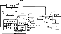
图5是说明如图1所示的核心节点A的信道的分插过程的示意图。出于清楚的目的,图5没有显示用于配置核心节点A和边缘节点300的所有器件,而显示了与信道的分插过程相关的某些器件,以及在信道上调制的多个帧。添加到每一个帧上的字符表示将核心节点100确定为帧的目的地。由于方便而非限定的缘故,在以下描述中,将帧A定义为其目的地是核心节点A的帧。FIG. 5 is a schematic diagram illustrating the process of adding and dropping channels of the core node A shown in FIG. 1 . For the purpose of clarity, Fig. 5 does not show all the devices used to configure the core node A and the
首先,将对于核心节点的信道的分出过程进行描述,然后对于核心节点A的信道插入过程进行描述。Firstly, the channel dropping process of the core node will be described, and then the channel insertion process of the core node A will be described.
控制器170通过由抽头耦合器155分路的信道部分,识别每一个帧的对应的目的地,并且检测目标为对应的目的地的帧。此外,控制器170向对应的光开关135输出用于分出检测到的帧的控制信号。将帧C、A和B按顺序输入到光开关135。然后,控制器170识别到帧A的目的地是核心节点A 100,则向对应的光开关135输出控制信号。光开关135执行开关操作,并且将第三信道λ3输入到去往边缘节点A’300的出口节点410。The
以下将参考图6,按照时间顺序来描述分出过程。在The drop process will be described below in chronological order with reference to FIG. 6 . exist
在Tn-1,输入帧C。由于帧C将核心节点C作为它的目的地,它通过光开关135。At T n-1 , frame C is input. Since frame C has core node C as its destination, it passes through
在Tn,输入帧A,控制器170向光开关135输出控制信号。当光开关135执行开关操作时,将帧A输出到去往边缘节点A’300的出口节点410。At T n , frame A is input, and the
在Tn+1,输入帧B,控制器170向光开关135输出控制信号。当光开关135执行开关操作时,将帧B输出到复用器140。更具体地说,因为帧B的目的地是核心节点B,帧B通过光开关135。At T n+1 , frame B is input, and the
现在,将描述核心节点A 100的信道的插入过程。Now, the insertion process of the channel of the
控制器170确定用于使在入口节点310创建的帧D被传送的光纤链路、信道和时刻。将帧D的突发数据存储于突发组装器350的缓冲器355中。入口节点310的第二电交换机360保持突发数据的存储,直到从控制器170输入控制信号。控制器170通过分路部分150识别在网络中所有信道的情况。对于在突发组装器350中存储的所有突发数据,控制器确定应该在考虑QOS、通信协议等的情况下应该按顺序传输的突发数据,并且对于空的时隙检查所有的信道。然后。在控制器170中,当选择最优化信道和空时隙时,将控制信号输出到入口节点310中的第二电交换机360。将处于等待状态的突发数据和头数据都绑定为帧,并且将由帧调制的信道输出到光开关135。然后,信道通过光开关135,并且被输入到复用器140。The
以下将参考图形特别是图6来描述信道的插入过程。此时,假定控制器170在Tn选择第三信道λ3的时隙。The channel insertion process will be described below with reference to figures, particularly FIG. 6 . At this time, it is assumed that the
在控制器170中,用于传输的突发数据持续在等待状态直到Tn。在Tn,将控制信号输出到第二电交换机360。第二电交换机360导致在其上存储有突发数据的缓冲器355与对应的头添加器375连接。头添加器375通过使用对应的头数据绑定突发数据来创建帧。接下来,对应的光发射器385将由帧调制的信道输出到光开关135。然后,将信道通过光开关135输出到复用器140。In the
很重要的是,依据本发明的光环形网能够依据由突发数据和头数据组成的帧执行通信,以致于适合于大容量的突发数据的传输。此外,当执行信道插入或者分出过程时,光环形网具有使用抽头耦合器、光开关等的简单配置。因此,从技术和经济的观点来看,它具有极好的实现能力。而且,通过在边缘节点中使用电缓冲器,光环形网具有在网络中的改进的带宽性能。It is very important that the optical ring network according to the present invention can perform communication according to the frame composed of burst data and header data, so that it is suitable for the transmission of large-capacity burst data. Furthermore, the optical ring network has a simple configuration using a tap coupler, an optical switch, etc. when performing a channel add or drop process. Therefore, it has excellent realizability from a technical and economical point of view. Also, by using electrical buffers in the edge nodes, the optical ring network has improved bandwidth performance in the network.
虽然出于说明的目的已经描述了本发明的优选实施例,本领域的技术人员将会意识到在不偏离在所附权利要求提出的本发明的范围和精神的情况下,可以进行各种修改、添加和替换。While the preferred embodiment of the invention has been described for purposes of illustration, those skilled in the art will recognize that various modifications can be made without departing from the scope and spirit of the invention as set forth in the appended claims , Add and Replace.
Claims (4)
Applications Claiming Priority (2)
| Application Number | Priority Date | Filing Date | Title |
|---|---|---|---|
| KR62248/2002 | 2002-10-12 | ||
| KR10-2002-0062248A KR100474694B1 (en) | 2002-10-12 | 2002-10-12 | Optical ring network for burst data communication |
Publications (2)
| Publication Number | Publication Date |
|---|---|
| CN1489322A CN1489322A (en) | 2004-04-14 |
| CN1274103C true CN1274103C (en) | 2006-09-06 |
Family
ID=32026146
Family Applications (1)
| Application Number | Title | Priority Date | Filing Date |
|---|---|---|---|
| CNB031450806A Expired - Fee Related CN1274103C (en) | 2002-10-12 | 2003-06-27 | Optical ring net for burst data communication |
Country Status (5)
| Country | Link |
|---|---|
| US (1) | US7272311B2 (en) |
| EP (1) | EP1408714B1 (en) |
| JP (1) | JP2004135352A (en) |
| KR (1) | KR100474694B1 (en) |
| CN (1) | CN1274103C (en) |
Families Citing this family (11)
| Publication number | Priority date | Publication date | Assignee | Title |
|---|---|---|---|---|
| KR100472951B1 (en) * | 2002-10-30 | 2005-03-10 | 한국전자통신연구원 | An Optical Burst Assemble Simulating Apparatus for Optical Burst Switching Network |
| US7359396B1 (en) * | 2003-10-09 | 2008-04-15 | Nortel Networks Limited | Optical-core network with selective signal queueing |
| KR100661348B1 (en) | 2004-11-03 | 2006-12-27 | 삼성전자주식회사 | Apparatus and Method for Label Transmission in Optical Packet Data Switching Network |
| EP1657952B1 (en) * | 2004-11-12 | 2008-07-02 | Nokia Siemens Networks Gmbh & Co. Kg | A ring network for a burst switching network with distributed management |
| JP4593267B2 (en) * | 2004-12-28 | 2010-12-08 | 富士通株式会社 | Optical node and optical add / drop multiplexer |
| US7676154B2 (en) * | 2006-06-29 | 2010-03-09 | Nortel Networks Limited | Method and system for configuring a connection-oriented packet network over a wavelength division multiplexed optical network |
| CN101557339B (en) * | 2008-04-09 | 2012-04-04 | 华为技术有限公司 | Data transmission method, data processing node and data transmission system |
| US9130691B2 (en) * | 2013-02-25 | 2015-09-08 | Verizon Patent And Licensing Inc. | Optical burst switched network nodes |
| CN104301027B (en) * | 2013-07-16 | 2018-10-26 | 南京中兴新软件有限责任公司 | Method, system and the node of automatic protection switching are realized in optical outburst switching loop network |
| CN104348551B (en) * | 2013-07-23 | 2018-12-28 | 中兴通讯股份有限公司 | A kind of the dynamic bandwidth dispatching method and device of smooth burst mode transmission looped network |
| CN105744385B (en) * | 2014-12-10 | 2020-06-16 | 中兴通讯股份有限公司 | A kind of transmission method and system of optical burst transmission network |
Family Cites Families (17)
| Publication number | Priority date | Publication date | Assignee | Title |
|---|---|---|---|---|
| KR960004720B1 (en) * | 1993-12-10 | 1996-04-12 | 재단법인한국전자통신연구소 | A fault-tolerant optical ring network |
| CA2164356A1 (en) * | 1994-12-07 | 1996-06-08 | Tyco Submarine Systems Ltd. | Wavelength division multiplexed hybrid ring suitable for use in regional area networks |
| KR100256683B1 (en) * | 1997-11-26 | 2000-05-15 | 이계철 | Branch and combined control device using control signal |
| KR20010034424A (en) * | 1998-02-04 | 2001-04-25 | 크로마티스 네트워크스, 인크. | Virtual star network |
| US6233074B1 (en) * | 1998-05-18 | 2001-05-15 | 3Com Corporation | Ring networks utilizing wave division multiplexing |
| US6111673A (en) * | 1998-07-17 | 2000-08-29 | Telcordia Technologies, Inc. | High-throughput, low-latency next generation internet networks using optical tag switching |
| JP3593921B2 (en) | 1999-06-01 | 2004-11-24 | 日本電気株式会社 | Packet transfer method and apparatus |
| JP3761362B2 (en) * | 1999-07-28 | 2006-03-29 | 沖電気工業株式会社 | Node control device, node device, optical network system, and optical path setting method |
| US6810211B1 (en) * | 1999-09-08 | 2004-10-26 | Alcatel | Preferred WDM packet-switched router architecture and method for generating same |
| JP3367499B2 (en) | 2000-02-25 | 2003-01-14 | 日本電気株式会社 | Ultra-high-speed network construction method |
| JP2002026982A (en) | 2000-07-07 | 2002-01-25 | Nippon Telegr & Teleph Corp <Ntt> | Packet switch |
| US6665495B1 (en) * | 2000-10-27 | 2003-12-16 | Yotta Networks, Inc. | Non-blocking, scalable optical router architecture and method for routing optical traffic |
| US6850515B2 (en) * | 2001-01-30 | 2005-02-01 | The Regents Of The University Of California | Optical layer multicasting using a single sub-carrier header and a multicast switch with active header insertion via light circulation |
| KR100411734B1 (en) * | 2001-02-12 | 2003-12-18 | 한국과학기술원 | Bidirectional wavelength division multiplexed add/drop self-healing Metro-ring network |
| US6956868B2 (en) * | 2001-02-15 | 2005-10-18 | Chunming Qiao | Labeled optical burst switching for IP-over-WDM integration |
| KR100467321B1 (en) * | 2002-06-17 | 2005-01-24 | 한국전자통신연구원 | Scheduling method in optical burst switching network, and header packet data structure therein |
| KR100487201B1 (en) * | 2003-02-04 | 2005-05-04 | 삼성전자주식회사 | High capacity router employing electrical buffer memory |
-
2002
- 2002-10-12 KR KR10-2002-0062248A patent/KR100474694B1/en not_active Expired - Fee Related
-
2003
- 2003-06-06 US US10/456,166 patent/US7272311B2/en not_active Expired - Fee Related
- 2003-06-27 CN CNB031450806A patent/CN1274103C/en not_active Expired - Fee Related
- 2003-10-10 EP EP03023121.1A patent/EP1408714B1/en not_active Expired - Lifetime
- 2003-10-14 JP JP2003353105A patent/JP2004135352A/en active Pending
Also Published As
| Publication number | Publication date |
|---|---|
| US7272311B2 (en) | 2007-09-18 |
| EP1408714A2 (en) | 2004-04-14 |
| KR100474694B1 (en) | 2005-03-10 |
| EP1408714B1 (en) | 2014-02-26 |
| US20040213572A1 (en) | 2004-10-28 |
| JP2004135352A (en) | 2004-04-30 |
| CN1489322A (en) | 2004-04-14 |
| KR20040035901A (en) | 2004-04-30 |
| EP1408714A3 (en) | 2011-09-07 |
Similar Documents
| Publication | Publication Date | Title |
|---|---|---|
| CN1183720C (en) | Optical communications network | |
| CN100499435C (en) | Optical multiring net for burst data communication | |
| CN100420309C (en) | Large Capacity Optical Router Using Electrical Buffer | |
| KR100493096B1 (en) | Apparatus and Method of Fast Optical Routing | |
| US7181140B2 (en) | Method and apparatus for implementing and networking a semiconductor-based optical burst switching module within optical networks | |
| CN1332546A (en) | Light IP exchange route structure | |
| CN1309852A (en) | High-throughput, low-latency next-generation Internet using optical label switching | |
| US20100061726A1 (en) | Dynamically Reconfiguring An Optical Network Using An Ethernet Switch | |
| CN1274103C (en) | Optical ring net for burst data communication | |
| US7885546B2 (en) | Method and apparatus for transparent Ethernet multiplexing and demultiplexing | |
| CN1178432C (en) | Communication system and method of operating a node in the communication system | |
| US8155521B2 (en) | Multi-degree cross-connector system, operating method and optical communication network using the same | |
| CN1559113A (en) | Ring Network Constructed by Dual Optical Data Bus | |
| CN101093264A (en) | Method for solving link configuration and wavelength allocation competed in OBS by using parallel light fiber | |
| CN1625091A (en) | Device, system and method for raising availability of photo-communication wavelength | |
| CN1372400A (en) | Integrated intelligent photoelectric mixed router | |
| KR100565943B1 (en) | Wavelength Path Path Based Optical Packet Label Switching Device | |
| JP2000324162A (en) | Data transfer method, data transfer device, and optical communication network | |
| CN1224195C (en) | Large city remote optical communication network comprising ring core | |
| JP2004266451A (en) | Wavelength path switching traffic pattern changing apparatus and wavelength path switching traffic pattern changing method |
Legal Events
| Date | Code | Title | Description |
|---|---|---|---|
| C06 | Publication | ||
| PB01 | Publication | ||
| C10 | Entry into substantive examination | ||
| SE01 | Entry into force of request for substantive examination | ||
| C14 | Grant of patent or utility model | ||
| GR01 | Patent grant | ||
| CF01 | Termination of patent right due to non-payment of annual fee | ||
| CF01 | Termination of patent right due to non-payment of annual fee |
Granted publication date: 20060906 Termination date: 20170627 |