CN1274253A - Head clips for direction reversible fixed earphone - Google Patents

Head clips for direction reversible fixed earphone Download PDF

Info

Publication number
CN1274253A
CN1274253A CN00107616A CN00107616A CN1274253A CN 1274253 A CN1274253 A CN 1274253A CN 00107616 A CN00107616 A CN 00107616A CN 00107616 A CN00107616 A CN 00107616A CN 1274253 A CN1274253 A CN 1274253A
Authority
CN
China
Prior art keywords
head
earphone
clamp
wearer
counterpart
Prior art date
Legal status (The legal status is an assumption and is not a legal conclusion. Google has not performed a legal analysis and makes no representation as to the accuracy of the status listed.)
Granted
Application number
CN00107616A
Other languages
Chinese (zh)
Other versions
CN1148103C (en
Inventor
詹姆斯T·麦克唐纳
斯蒂芬R·莱曼
小约翰·德皮亚诺
罗伊·海因茨
Current Assignee (The listed assignees may be inaccurate. Google has not performed a legal analysis and makes no representation or warranty as to the accuracy of the list.)
GN Audio AS
Original Assignee
GN Netcom AS
Priority date (The priority date is an assumption and is not a legal conclusion. Google has not performed a legal analysis and makes no representation as to the accuracy of the date listed.)
Filing date
Publication date
Application filed by GN Netcom AS filed Critical GN Netcom AS
Publication of CN1274253A publication Critical patent/CN1274253A/en
Application granted granted Critical
Publication of CN1148103C publication Critical patent/CN1148103C/en
Anticipated expiration legal-status Critical
Expired - Fee Related legal-status Critical Current

Links

Images

Classifications

    • H—ELECTRICITY
    • H04—ELECTRIC COMMUNICATION TECHNIQUE
    • H04R—LOUDSPEAKERS, MICROPHONES, GRAMOPHONE PICK-UPS OR LIKE ACOUSTIC ELECTROMECHANICAL TRANSDUCERS; ELECTRIC HEARING AIDS; PUBLIC ADDRESS SYSTEMS
    • H04R1/00—Details of transducers, loudspeakers or microphones
    • H04R1/10—Earpieces; Attachments therefor ; Earphones; Monophonic headphones
    • H—ELECTRICITY
    • H04—ELECTRIC COMMUNICATION TECHNIQUE
    • H04R—LOUDSPEAKERS, MICROPHONES, GRAMOPHONE PICK-UPS OR LIKE ACOUSTIC ELECTROMECHANICAL TRANSDUCERS; ELECTRIC HEARING AIDS; PUBLIC ADDRESS SYSTEMS
    • H04R1/00—Details of transducers, loudspeakers or microphones
    • H04R1/08—Mouthpieces; Microphones; Attachments therefor
    • H04R1/083—Special constructions of mouthpieces
    • H—ELECTRICITY
    • H04—ELECTRIC COMMUNICATION TECHNIQUE
    • H04M—TELEPHONIC COMMUNICATION
    • H04M1/00—Substation equipment, e.g. for use by subscribers
    • H04M1/02—Constructional features of telephone sets
    • H04M1/04—Supports for telephone transmitters or receivers
    • H04M1/05—Supports for telephone transmitters or receivers specially adapted for use on head, throat or breast
    • H—ELECTRICITY
    • H04—ELECTRIC COMMUNICATION TECHNIQUE
    • H04R—LOUDSPEAKERS, MICROPHONES, GRAMOPHONE PICK-UPS OR LIKE ACOUSTIC ELECTROMECHANICAL TRANSDUCERS; ELECTRIC HEARING AIDS; PUBLIC ADDRESS SYSTEMS
    • H04R2201/00—Details of transducers, loudspeakers or microphones covered by H04R1/00 but not provided for in any of its subgroups
    • H04R2201/10—Details of earpieces, attachments therefor, earphones or monophonic headphones covered by H04R1/10 but not provided for in any of its subgroups
    • H04R2201/107—Monophonic and stereophonic headphones with microphone for two-way hands free communication

Landscapes

  • Engineering & Computer Science (AREA)
  • Signal Processing (AREA)
  • Physics & Mathematics (AREA)
  • Acoustics & Sound (AREA)
  • Health & Medical Sciences (AREA)
  • Otolaryngology (AREA)
  • Headphones And Earphones (AREA)
  • Telephone Set Structure (AREA)

Abstract

一种用于可换向地固定耳机的头夹,其中耳机可用于佩带者头部的任意一侧。头夹可包括两个可调整的连接部分以适应佩带者的头部。在头夹的一侧带有耳机用的配合件。该配合件可包括围绕圆形空腔的多个突起。可以通过将耳机的至少一部分装配在空腔内使耳机固定在头夹上,其中耳机由突起保持在适当的位置。可以设置突起的间隔以使耳机能从突起之间伸出,并可以由佩带者随意调整耳机。

Figure 00107616

A head clip for reversibly securing earphones, wherein the earphones can be used on either side of the wearer's head. The headgear may include two adjustable attachment portions to fit the wearer's head. On one side of the head clip there is a fitting for earphones. The fit may include a plurality of protrusions surrounding the circular cavity. The earphone may be secured to the head clip by fitting at least a portion of the earphone within the cavity, wherein the earphone is held in place by the protrusion. The distance between the protrusions can be set so that the earphone can protrude from between the protrusions, and the earphone can be adjusted by the wearer at will.

Figure 00107616

Description

Be used for the head-clamp of fixed earphone reversibly
The present invention relates to earphone, be specifically related to be used for the head-clamp of fixed earphone reversibly.
So-called earphone is used in the situation of various voice communications, for example, and the voice communication between individual and the communication network.In typical situation, the earphone that the caller wears comprises microphone and transducer (transducer), and earphone links to each other with telephone network by them.The caller can get phone and reply incoming call, and need not hand conventional receiver.The caller can vacate both hands and take notes, and knocks computer keyboard etc.
Conventional earphone is basically by a head-clamp that is fixed on the wearer crown, and at least one is formed near transducer and a microphone of wearer ear.Microphone is suspended on the part that has transducer from earphone usually, perhaps from the end of the extended suspension rod of head-clamp.
The latest development in earphone field has brought the earphone of a kind, and they are suspended on wearer's ear, and does not comprise the head-clamp on the crown that is positioned at the wearer.The some of them earphone has sprung parts, and certain part of the curved shape of sprung parts and wearer's ear is identical substantially.This sprung parts is the part of main earphone unit or is connected on the main earphone unit.Main earphone unit generally includes transducer and microphone and circuit etc.Another part of earphone (normally sounding transducer) can reach the good sound perception near wearer's ear when using earphone with box lunch.Used the form fit parts in other example of earphone, it conforms to the shape at ear canal aperture place substantially, thereby earphone is fixed on correct service position.
Yet there is shortcoming in the above-mentioned earphone that does not have head-clamp.Than the earphone that has head-clamp, they more are difficult to be fixedly secured the head the wearer.Its consequence is that the wearer can drop earphone because of carelessness, and this situation for example occurs in when head rocks, and when earphone bumps against fixed object, or when earphone cord takes place to twine.Usually, earphone will fall down, and this will be very bothersome experience undoubtedly, particularly when it occurs in the wearer and is just having conversation by earphone.In addition, drop on the floor from wearer's head, danger impaired or that damage is then arranged if having the earphone of sensitive electrical devices.Thereby, still need head-clamp as can be seen in the earphone, by earphone is fixed on the head-clamp, can increase fail safe and accuracy in the operation.
Another shortcoming of some existing earphone is that they only are suitable for being used in wearer's head one side.For example, earphone can be designed to only be worn on wearer's the auris dextra, the microphone of earphone is stretched out to wearer's right cheek or right jaw.Because earphone is in the extension of head one side and can not change opposite side, this long-time nonadjustable orientation will make the wearer feel worried, impatient and unhappy.And in some cases, wearer's service position has determined earphone must be worn over the particular side of head.For example, at client service location, the wearer of earphone may need directly to exchange with the client, and carries out electronic communication by earphone.Thereby the wearer wish with earphone be worn over away from its directly in the face of client's head side, thereby, so that make face-to-face exchange be unlikely to be subjected to the influence of earphone.
Therefore, need a kind of earphone that is designed to not take the lead to press from both sides use, and it can use also if desired with head-clamp.As can be seen, need a kind of head-clamp of fixed earphone reversibly, thereby make earphone can be worn over any side of wearer's head.
The present invention relates generally to earphone, and be specifically related to earphone reversibly to be fixed on the head-clamp of any side of head.
The head-clamp that a kind of earphone is used comprises the parts that can be positioned wearer's head.These parts have the counterpart that is used for earphone, and this counterpart comprises a plurality of strutting pieces.These a plurality of strutting pieces surround and have formed cavity to hold the part of earphone, and wherein by strutting piece, earphone is fixed on the counterpart releasedly, so that can wear head-clamp under earphone is positioned at the situation of any side of wearer's head.Described strutting piece can have radially the projection towards cavity in its end.
The position of a strutting piece is relative with the joint of head-clamp with described counterpart.Have between two adjacent strutting pieces at interval, so that earphone is from wherein stretching out.Have between described two adjacent strutting pieces at interval, so that can adjust the position of earphone betwixt.
The head-clamp that a kind of earphone is used comprises first and second parts that can be positioned wearer's head at least.In order to adjust the relative position of head-clamp and wearer's head, described two parts connect mutually adjustably.Head-clamp comprises that also the earphone that is positioned in the first is with counterpart be positioned at head support thing on the second portion.Described counterpart is fixed in the first by swivel joint.The head support thing comprises the extension component on the transverse direction that rotatably is fixed on second portion.Described counterpart comprises that opening is roughly circular housing, and three projections are centered around around the housing.Projection is covering shell partly, and wherein earphone is fixed on enclosure interior adjustably, and keeps in position by projection.Therefore a projection is relative with swivel joint, and earphone is fixed in the described counterpart, can wear head-clamp under earphone is positioned at the situation of any side of wearer's head.
A kind of earphone carrier that comprises head-clamp, head-clamp are used to support the earphone near wearer's head.The earphone carrier also comprises the device that earphone reversibly can be fixed on the head-clamp, and wherein the earphone carrier can be used to any side of wearer's head.
Describe these and other novel advantage and characteristics as feature of the present invention in these claims in detail, they have constituted a part of the present invention.Yet, in order to understand the present invention and advantage thereof better, and use other purpose that is obtained by it, should be with reference to the accompanying drawing that constitutes a part of the present invention, and subsidiary illustrative words, diagram has therein also been described the preferred embodiments of the present invention.
The present invention is described below with reference to accompanying drawings, the wherein identical corresponding or identical parts of reference symbol representative, wherein:
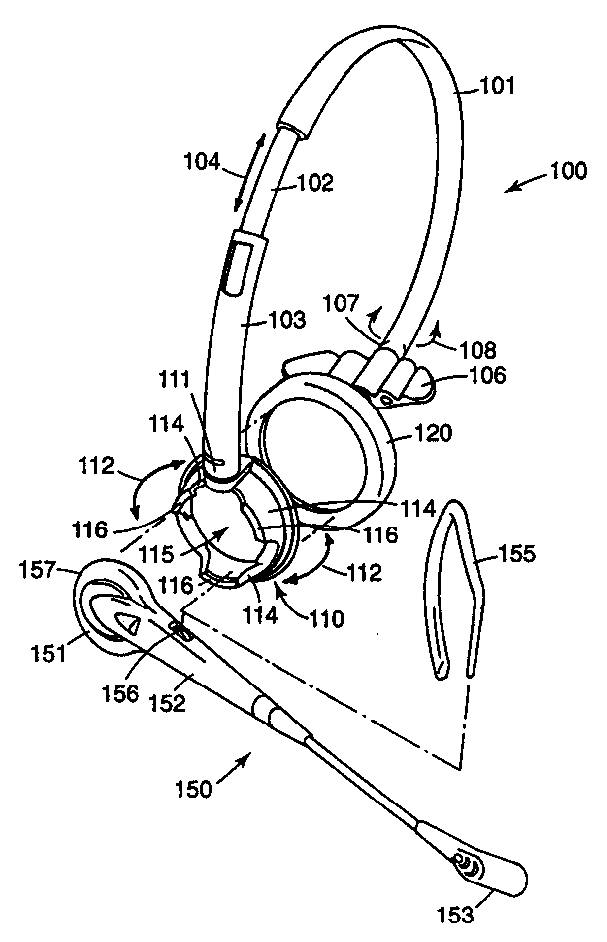
Fig. 1 is the three-dimensional exploded view of one embodiment of the invention; With
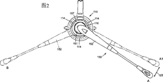
Fig. 2 is for showing the fixed partial view of the capable of reversing and adjustable solidating of earphone.
Fig. 1 has showed an embodiment according to head-clamp 100 of the present invention.Head-clamp 100 can be worn over wearer's head, makes the wearer can use earphone.Head-clamp 100 comprises first 101.This part 101 has crooked shape, with the shape of engagement head, and comprises the sheet shape piece 102 that stretches out from the one end.Sheet shape piece 102 is connected adjustably with the second portion 103 of head-clamp 100.Shown in arrow 104, the connection adjusted between two parts can be adjusted the size of head-clamp 100.
Head-clamp 100 also comprises the headrest 106 that links to each other with first 101.Headrest 106 is used to make head-clamp 100 more comfortable and be securely fixed in wearer's head.Shown in arrow 108, headrest 106 rotatably is fixed in the first 101.For example, it is 106 fixing to adopt swivel joint 107 to rest the head on.
Head-clamp 100 also comprises the counterpart 110 that links to each other with second portion 103.Counterpart 110 is used for earphone 150 is fixed on head-clamp 100, allows the wearer that earphone 150 is used with head-clamp 100.Shown in arrow 112, counterpart 110 rotatably is connected on the second portion 103.For example, counterpart 110 can pass through swivel joint, and for example swivel (swivel) 111 connects.
Counterpart 110 comprises three strutting pieces 114.In an illustrated embodiment, three strutting piece 114 common housings that constitute circular.In other embodiments, strutting piece 114 can have different structures.When earphone 150 was installed on the head-clamp 100, strutting piece 114 was used for fixing earphone 150.In a kind of special applications, the shape of three strutting pieces 114 and/or structure can closely center on them and are engaged on the part of earphone 150.
In the embodiment shown in fig. 1, strutting piece 114 is slight curving, thereby can closely be fitted on the circular portion 157 of transducer end 151 of earphone 150.As mentioned below, closely cooperating between strutting piece 114 and the circular portion 157 to fixedly securing of earphone 150 provides condition, and earphone 150 is fixed in the counterpart 110 adjustably.
As can be seen from Figure 1, when putting on head-clamp 100, counterpart 110 has roughly symmetrical structure with respect to the longitudinal axis.Form cavity 115 between three strutting pieces 114, one of them strutting piece 114 is positioned at the position roughly relative with swivel 111.
Counterpart 110 has earphone pad 120.In illustrated embodiment,, can guarantee that earphone 150 transmits sound well to wearer's ear when cavity 115 during by whole counterpart 110.In order to make head-clamp 100 more comfortable, earphone pad 120 covers the opening of counterpart and cavity 115.
Illustrated earphone 150 only is one of example of numerous earphones that can use with head-clamp 100.Earphone 150 comprises transducer end 151 and microphone end 153.Transducer end 151 links to each other by main body 152 with microphone end 153.Illustrated earphone 150 also comprises tack 155, and tack 155 is fixed in the shaft coupling 156 in the main body 152 adjustably.By tack 155 being fixed on wearer's the ear, illustrated earphone 150 can not use with head-clamp 100.151 at transducer end abuts on the outer auricle, and the position of earphone 150 can be adjusted by shaft coupling 156.Yet, as described in the background section, wish that above-mentioned earphone 150 uses with head-clamp 100.Can easily earphone 150 be fixed on the head-clamp 100 by counterpart 110.
In the embodiment shown in fig. 1, have projection 116 in the end of strutting piece 114.Projection 116 is radially inwardly towards cavity 115, thereby earphone 150 can be kept in position.Can consider the size and/or the structure of the incompatible selection projection 116 of applied field of head-clamp 100.Especially, can make projection 116 cooperate the special shape of the transducer end 151 of employed earphone 150.Under some application scenario, strutting piece 114 relies on their elastic force and/or skin-friction force stationary transducer end 151.
Fig. 2 has showed that earphone 150 is fixed on the partial view of the embodiment in the counterpart 110.Transducer end 151 is arranged in cavity 115, makes main body 152 stretch out between two strutting pieces 114.Earphone can be adjusted between position A shown in the arrow 125 and position A1 (virtual image) gradually.The circular portion 157 of transducer end 151 remains in the cavity 115 slidably.
Main body 152 is stretched out by the passage between two strutting pieces 114.In illustrated embodiment, the width of main body 152 is less than 114 width of channel of strutting piece, thereby can adjust earphone 150.In other embodiments, main body 152 can and the passage of 114 of strutting pieces have roughly the same width so that it can not be adjusted betwixt.
Shown in the B of virtual image position, earphone 150 can be fixed on the counterpart 110 from another direction.In the illustrated embodiment, counterpart 110 is symmetrically distributed with respect to the longitudinal axis, and main body 152 can be fixed between two strutting pieces 114, its structure and position A symmetry.Thereby, can make head-clamp 100 and earphone 150 be worn over any side of wearer's head.Main body 152 is stretched out between two strutting pieces 114 among the virtual image B, is similar to position A and A1, by the position of two strutting pieces 114 is set, can adjust earphone 150 gradually between the two.
Thereby head-clamp 100 provides convenience for fixed earphone (for example earphone 150).Earphone is supported adjustably and can be fixed from different directions by head-clamp, therefore can wear head-clamp under earphone is positioned at the situation of any side of head.
Although the present invention is described, should be understood that content of the present invention is not limited to this embodiment by an embodiment.All conversion of making under the spirit and scope of the present invention that are defined by the following claims improve and replacement of equal value is all answered in the present invention involved.

Claims (12)

1. head-clamp that earphone is used comprises:
Can be positioned at the parts on the wearer crown, these parts have the counterpart that is used for earphone;
Wherein this counterpart comprises a plurality of strutting pieces, a plurality of strutting pieces surround and form cavity to hold the part of earphone, wherein by strutting piece, earphone is fixed on the counterpart releasedly, reversibly wears head-clamp so that be at earphone under the situation of any side of wearer's head.
2. according to the head-clamp of claim 1, it is characterized in that described counterpart is fixed on the head-clamp by swivel.
3. according to the head-clamp of claim 1, it is characterized in that the end of each strutting piece has projection, projection is radially towards cavity.
4. according to the head-clamp of claim 1, it is characterized in that cavity is roughly circle.
5. according to the head-clamp of claim 1, it is characterized in that when head-clamp was positioned at wearer's head, described counterpart was with respect to longitudinal axis symmetry.
6. according to the head-clamp of claim 1, it is characterized in that the position of a strutting piece is relative with the joint of head-clamp with described counterpart.
7. according to the head-clamp of claim 1, it is characterized in that having between two adjacent strutting pieces at interval, so that earphone is from wherein stretching out.
8. according to the head-clamp of claim 7, it is characterized in that having between two adjacent strutting pieces at interval, so that can adjust the position of earphone betwixt.
9. according to the head-clamp of claim 1, it is characterized in that having at interval between the first and second adjacent strutting pieces so that earphone is from wherein stretching out, and second and third phase neighbour's strutting piece between have at interval so that earphone is from wherein stretching out.
10. according to the head-clamp of claim 1, it is characterized in that described counterpart comprises opening, when putting on head-clamp, opening is between earphone and wearer's ear.
11. the head-clamp that earphone is used comprises:
Can be positioned at least the first and second parts of wearer's head, in order to adjust the relative position of head-clamp and wearer's head, described two parts connect mutually adjustably;
Be positioned at earphone in the first with counterpart be positioned at head support thing on the second portion, described counterpart is fixed in the first by swivel joint, and the head support thing comprises the extension component on the transverse direction that rotatably is fixed on second portion;
Wherein said counterpart comprises that opening is roughly circular housing, three projections are centered around around the housing and covering shell partly, wherein earphone is fixed on enclosure interior adjustably, and it is fixing in position by projection, and one of them projection is relative with swivel joint, therefore earphone is fixed in the described counterpart, can under earphone is in the situation of any side of wearer's head, wears head-clamp.
12. an earphone carrier comprises:
Be used to support head-clamp near the earphone of wearer's head; With
Be used for earphone reversibly is fixed on device on the head-clamp, wherein the earphone carrier can be used to any side of wearer's head.
CNB001076167A 1999-05-14 2000-05-15 Head clips for direction reversible fixed earphone Expired - Fee Related CN1148103C (en)

Applications Claiming Priority (2)

Application Number Priority Date Filing Date Title
US09/312,443 1999-05-14
US09/312,443 US6356635B1 (en) 1999-05-14 1999-05-14 Headband for reversible mounting of headsets

Publications (2)

Publication Number Publication Date
CN1274253A true CN1274253A (en) 2000-11-22
CN1148103C CN1148103C (en) 2004-04-28

Family

ID=23211463

Family Applications (1)

Application Number Title Priority Date Filing Date
CNB001076167A Expired - Fee Related CN1148103C (en) 1999-05-14 2000-05-15 Head clips for direction reversible fixed earphone

Country Status (10)

Country Link
US (1) US6356635B1 (en)
EP (1) EP1052829B1 (en)
JP (1) JP2000354288A (en)
KR (1) KR100668033B1 (en)
CN (1) CN1148103C (en)
AT (1) ATE372641T1 (en)
AU (1) AU775510B2 (en)
CA (1) CA2308364A1 (en)
DE (1) DE60036246T2 (en)
MX (1) MXPA00004615A (en)

Cited By (5)

* Cited by examiner, † Cited by third party
Publication number Priority date Publication date Assignee Title
CN100377621C (en) * 2003-02-07 2008-03-26 三星电子株式会社 3-Axis Rotating Wireless Headphones
CN101883302A (en) * 2009-05-06 2010-11-10 罗杰泰克欧洲股份有限公司 Personal audio set with adjustable force mechanisms
CN1929693B (en) * 2005-09-05 2012-06-13 索尼株式会社 Headphones and headphones placement device
CN101843113B (en) * 2007-10-31 2014-06-18 Gn奈康有限公司 Communication device with combined electrical socket and microphone port
CN105635879A (en) * 2016-02-04 2016-06-01 维朔控股有限公司 An ergonomic headset

Families Citing this family (44)

* Cited by examiner, † Cited by third party
Publication number Priority date Publication date Assignee Title
US20020111197A1 (en) * 2001-01-04 2002-08-15 Fitzgerald Robert M. Cordless telephone headset system
US7181037B2 (en) 2001-03-16 2007-02-20 Gn Netcom A/S Headset with adjustable microphone boom
US6910911B2 (en) 2002-06-27 2005-06-28 Vocollect, Inc. Break-away electrical connector
US20100022281A1 (en) * 2005-01-05 2010-01-28 Cohen Arthur L Wireless phone headset
ES1059932Y (en) * 2005-03-30 2005-10-01 Southwing S L MULTIFUNCTIONAL ARM FOR WIRELESS TELEPHONE HEADPHONE.
USD530702S1 (en) * 2005-10-04 2006-10-24 Motorola, Inc. Headset
USD549694S1 (en) 2005-11-15 2007-08-28 Vocollect, Inc. Headset
USD552595S1 (en) 2005-11-16 2007-10-09 Vocollect, Inc. Control panel for a headset
US8417185B2 (en) 2005-12-16 2013-04-09 Vocollect, Inc. Wireless headset and method for robust voice data communication
US7773767B2 (en) 2006-02-06 2010-08-10 Vocollect, Inc. Headset terminal with rear stability strap
US7885419B2 (en) * 2006-02-06 2011-02-08 Vocollect, Inc. Headset terminal with speech functionality
JP2009033504A (en) * 2007-07-27 2009-02-12 Nec Tokin Corp Bone conduction type receiver
USD626949S1 (en) 2008-02-20 2010-11-09 Vocollect Healthcare Systems, Inc. Body-worn mobile device
USD605629S1 (en) 2008-09-29 2009-12-08 Vocollect, Inc. Headset
US8386261B2 (en) 2008-11-14 2013-02-26 Vocollect Healthcare Systems, Inc. Training/coaching system for a voice-enabled work environment
US8160287B2 (en) 2009-05-22 2012-04-17 Vocollect, Inc. Headset with adjustable headband
US8438659B2 (en) 2009-11-05 2013-05-07 Vocollect, Inc. Portable computing device and headset interface
USD639776S1 (en) * 2010-03-03 2011-06-14 Victor Company Of Japan, Limited Portion of headphone
US8659397B2 (en) 2010-07-22 2014-02-25 Vocollect, Inc. Method and system for correctly identifying specific RFID tags
USD643400S1 (en) 2010-08-19 2011-08-16 Vocollect Healthcare Systems, Inc. Body-worn mobile device
USD643013S1 (en) 2010-08-20 2011-08-09 Vocollect Healthcare Systems, Inc. Body-worn mobile device
US8994610B2 (en) * 2010-11-08 2015-03-31 Symbol Technologies, Inc. User configurable headset
WO2013019950A1 (en) * 2011-08-02 2013-02-07 Tankersley Amy Ear warmer
KR101188298B1 (en) 2011-11-04 2012-10-08 삼성탈레스 주식회사 Headset having the plural connecting member
WO2016112000A1 (en) 2015-01-05 2016-07-14 Gecawicz Raymond Modular headset with pivotable boom and speaker module
USD760689S1 (en) * 2015-10-08 2016-07-05 Raymond Gecawicz Headset
USD760690S1 (en) * 2015-10-09 2016-07-05 Raymond Gecawicz Headset
CN105554603B (en) * 2015-12-04 2019-11-15 魅族科技(中国)有限公司 Earphone and link assembly
USD832232S1 (en) * 2016-08-31 2018-10-30 Harman International Industries, Incorporated Headphone
USD786826S1 (en) * 2016-10-10 2017-05-16 Premier Accessory Group LLC Headset
USD847782S1 (en) * 2017-02-08 2019-05-07 Sennheiser Communications A/S Snap on-off headset
USD847783S1 (en) * 2017-02-09 2019-05-07 Sennheiser Communications A/S Headset including an earhook
USD851628S1 (en) * 2017-02-09 2019-06-18 Sennheiser Communications A/S Headset including a headband
USD847784S1 (en) * 2017-02-20 2019-05-07 Sennheiser Communications A/S Headset including a neckband
USD822638S1 (en) * 2017-03-10 2018-07-10 Sky Wing Communication Electronics Co., Ltd. Headset
KR102147428B1 (en) * 2020-04-01 2020-08-24 김종성 Multifunctional face massager
USD968367S1 (en) * 2020-05-01 2022-11-01 Rtx A/S Headset
JP1693866S (en) * 2021-04-14 2021-08-30
JP1693865S (en) * 2021-04-14 2021-08-30
TWD223257S (en) 2021-10-22 2023-01-21 大陸商深圳市韶音科技有限公司 earphone
USD1080580S1 (en) 2021-10-22 2025-06-24 Shenzhen Shokz Co., Ltd. Speaker covers of headphones
TWD223256S (en) 2021-10-22 2023-01-21 大陸商深圳市韶音科技有限公司 earphone
USD1010612S1 (en) 2021-12-20 2024-01-09 Raymond Gecawicz Headset
USD1005260S1 (en) * 2023-08-15 2023-11-21 Yuliang Wu Headphone

Family Cites Families (57)

* Cited by examiner, † Cited by third party
Publication number Priority date Publication date Assignee Title
US1587643A (en) 1925-06-02 1926-06-08 Dictograph Products Corp Ear-loop attachment for deaf phones
US2485405A (en) 1944-04-21 1949-10-18 Stromberg Carlson Co Dipole microphone
US2506490A (en) 1946-08-30 1950-05-02 William R Coley Earpiece with plural sound passages
US2513746A (en) 1947-02-10 1950-07-04 Carl P Rohr Hearing aid support
US2481387A (en) 1947-04-07 1949-09-06 Archie O Bonecutter Telephone holder
US2474135A (en) 1947-06-05 1949-06-21 Gray Mfg Co Adjustable earpiece support
US2586644A (en) 1949-02-10 1952-02-19 Telex Inc Headset
US2606255A (en) 1949-11-29 1952-08-05 Lester P Burrow Telephone receiver holder
US2939923A (en) 1955-08-03 1960-06-07 John D Henderson Hearing aid plastic ear pieces
US3440365A (en) 1965-11-04 1969-04-22 Bell Telephone Labor Inc Telephone headset with adjustable speech tube
AT297111B (en) 1970-04-08 1972-03-10 Akg Akustische Kino Geraete Headband for headphones
GB1377237A (en) 1972-09-13 1974-12-11 Standard Telephones Cables Ltd Telephone headset
US3862378A (en) 1973-12-06 1975-01-21 J Ray Norris Ear set
US3971900A (en) * 1975-03-05 1976-07-27 Roanwell Corporation Communications headset with rotatable and tiltable electrical connector
US3993879A (en) 1975-03-24 1976-11-23 Wallace Keith Larkin Acoustical communications headset
US4118606A (en) 1975-03-24 1978-10-03 Wallace Keith Larkin Acoustical voice transmitting headset
USD242724S (en) 1975-11-19 1976-12-14 Brodie S Dan Headset
US4020297A (en) 1976-01-15 1977-04-26 Brodie S Dan Adjustable headset
US4048453A (en) 1976-02-11 1977-09-13 Gustave Seidel Telephone handset support device
GB2036505B (en) 1978-11-16 1983-04-13 Zichy T Ear-supported microphone
USD272904S (en) 1981-02-17 1984-03-06 Sony Corporation Earphone
NL8400925A (en) 1984-03-23 1985-10-16 Philips Nv HEARING AID, IN PARTICULAR BEHIND-THE-EAR HEARING AID.
USD293107S (en) 1985-04-26 1987-12-08 AS Electronics AG Radio
US4754484A (en) * 1986-08-21 1988-06-28 Acs Communications, Inc. Convertible handset/headset for telephone
US4864610A (en) 1987-02-27 1989-09-05 Acs Communications, Inc. Earpiece for a telephone headset
DK157282C (en) 1987-09-30 1990-05-07 Gn Netcom As THE HEADPHONE PHONE WITH ANGLE HOOK AND EQUIPPED TO BE BEARED ON THE OUTER OVER
USD311521S (en) 1987-09-30 1990-10-23 Gn Netcom A/S Combined earphone and microphone
US4972468A (en) 1987-10-14 1990-11-20 Sanshin Kogyo Kabushiki Kaisha Transceiver for hanging on an ear
US4875237A (en) * 1988-05-31 1989-10-24 Stephen Cohen Jacket for displaying information
GB8904912D0 (en) * 1989-03-03 1989-04-12 Carlyle Investments Limited Telephone support device
US5058155A (en) 1989-12-01 1991-10-15 Gn Netcom A/S Multipurpose headset amplifier
USD326653S (en) 1989-12-12 1992-06-02 Sony Corporation Radio receiver
US5035005A (en) * 1990-07-27 1991-07-30 Hung Huang C Inflight headset for civil aircraft
US5210792A (en) 1990-08-13 1993-05-11 Matsushita Electric Industrial Co., Ltd. Ear-hang type headset
US5191602A (en) 1991-01-09 1993-03-02 Plantronics, Inc. Cellular telephone headset
USD339355S (en) 1991-02-26 1993-09-14 Acs Communications Telephone headset
US5702829A (en) * 1991-10-14 1997-12-30 Commissariat A L'energie Atomique Multilayer material, anti-erosion and anti-abrasion coating incorporating said multilayer material
US5412736A (en) 1992-03-23 1995-05-02 Keliiliki; Shawn P. Personal audio system and earphone for same
US5469505A (en) * 1992-07-08 1995-11-21 Acs Wireless, Inc. Communications headset having a ball joint-mounted receiver assembly
US5446788A (en) 1992-09-29 1995-08-29 Unex Corporation Adjustable telephone headset
US5715321A (en) 1992-10-29 1998-02-03 Andrea Electronics Coporation Noise cancellation headset for use with stand or worn on ear
DE9302862U1 (en) * 1993-02-26 1993-05-27 Anton Steinecker Entwicklungs GmbH & Co, 8050 Freising Aeration nozzle for aerating liquids containing organic substances
US5450496A (en) 1993-07-30 1995-09-12 Acs Communications, Inc. Communications headset having a detachable receiver capsule and cable pivot
USD357479S (en) 1993-12-16 1995-04-18 U.S. Philips Corporation Earphone
US5655026A (en) 1993-12-23 1997-08-05 Otto Engineering, Inc. Ear receiver
US5796821A (en) 1994-01-05 1998-08-18 Crouch; Shirley Aline Hearing aid telephone interconnect system
USD366486S (en) 1994-10-11 1996-01-23 Telex Communications, Inc. Headset
USD363487S (en) 1994-10-17 1995-10-24 Telex Communications, Inc. Headset ear piece
USD384958S (en) 1995-05-09 1997-10-14 Sony Corporation Earphone with microphone
US5625171A (en) 1995-05-09 1997-04-29 Marshall; Christina M. Interchangeable earpiece for stereo listening
DK0749263T3 (en) 1995-06-13 2000-01-31 Gn Netcom As Headphone with adjustable ear hook
USD375313S (en) 1995-06-13 1996-11-05 Gn Netcom A/S Headset with adjustable earhook
USD385272S (en) 1996-06-21 1997-10-21 Acs Wireless, Inc. Communication headset
CA2194641C (en) 1996-12-28 2005-05-03 Bill Yang In-ear type earphone having an ear hanger
USD403327S (en) 1997-09-23 1998-12-29 Plantronics, Inc. Convertible earhook headset
USD409621S (en) 1997-09-30 1999-05-11 Andrea Electronics Corporation Headset
USD407089S (en) 1998-05-07 1999-03-23 Joakim Norin Telephone headset

Cited By (5)

* Cited by examiner, † Cited by third party
Publication number Priority date Publication date Assignee Title
CN100377621C (en) * 2003-02-07 2008-03-26 三星电子株式会社 3-Axis Rotating Wireless Headphones
CN1929693B (en) * 2005-09-05 2012-06-13 索尼株式会社 Headphones and headphones placement device
CN101843113B (en) * 2007-10-31 2014-06-18 Gn奈康有限公司 Communication device with combined electrical socket and microphone port
CN101883302A (en) * 2009-05-06 2010-11-10 罗杰泰克欧洲股份有限公司 Personal audio set with adjustable force mechanisms
CN105635879A (en) * 2016-02-04 2016-06-01 维朔控股有限公司 An ergonomic headset

Also Published As

Publication number Publication date
US6356635B1 (en) 2002-03-12
DE60036246T2 (en) 2008-05-29
KR100668033B1 (en) 2007-01-15
KR20010049350A (en) 2001-06-15
EP1052829B1 (en) 2007-09-05
EP1052829A2 (en) 2000-11-15
ATE372641T1 (en) 2007-09-15
JP2000354288A (en) 2000-12-19
CN1148103C (en) 2004-04-28
DE60036246D1 (en) 2007-10-18
CA2308364A1 (en) 2000-11-14
EP1052829A3 (en) 2003-11-12
AU775510B2 (en) 2004-08-05
MXPA00004615A (en) 2002-06-04
AU3532500A (en) 2000-11-16

Similar Documents

Publication Publication Date Title
CN1148103C (en) Head clips for direction reversible fixed earphone
US7580541B2 (en) Personal audio-set with adjustable sliding ear clip mount
JP4118934B2 (en) Glasses type communication device
US10231048B2 (en) Ergonomic earpiece with attachment mount
US4993065A (en) Accessory communication device for telephone sets
RU2611215C1 (en) In-ear headphones (versions) and method of wearing them
EP1995988A1 (en) Structure for installing bone conduction device on eyeglasses
WO2024045045A1 (en) Earphone
CN1980487B (en) Bone-conduction head set type ear receiver
CN110199526A (en) Audio output device
US11252493B2 (en) Hearing device and earphone
KR200271600Y1 (en) An ear hanger type earphone-mike
JP6601689B2 (en) Bone conduction headset
WO2024045046A1 (en) Earpiece
KR20200021270A (en) Bone conduction earphone and package comprising the same
WO2005067654A2 (en) Personal audio-set with adjustable sliding ear clip mount
CN224164878U (en) A type of call center headset
CN215379201U (en) Novel bone conduction earphone
CN2410835Y (en) Hanger device for hanging earphones and microphones
WO2025261476A1 (en) Earphone
CN118509759A (en) Earphone
CN117676408A (en) a kind of earphone
WO2003075607A1 (en) Personal audio-set with pivoting ear clip mount
JPH04177997A (en) Ear mount type handset
JP2002305576A (en) Wireless communication terminal

Legal Events

Date Code Title Description
C06 Publication
PB01 Publication
C10 Entry into substantive examination
SE01 Entry into force of request for substantive examination
C14 Grant of patent or utility model
GR01 Patent grant
C17 Cessation of patent right
CF01 Termination of patent right due to non-payment of annual fee

Granted publication date: 20040428