CN1274376C - Self-Contained Sports Ball Inflator - Google Patents
Self-Contained Sports Ball Inflator Download PDFInfo
- Publication number
- CN1274376C CN1274376C CNB018141471A CN01814147A CN1274376C CN 1274376 C CN1274376 C CN 1274376C CN B018141471 A CNB018141471 A CN B018141471A CN 01814147 A CN01814147 A CN 01814147A CN 1274376 C CN1274376 C CN 1274376C
- Authority
- CN
- China
- Prior art keywords
- ball
- sport ball
- inflatable
- sport
- layer
- Prior art date
- Legal status (The legal status is an assumption and is not a legal conclusion. Google has not performed a legal analysis and makes no representation as to the accuracy of the status listed.)
- Expired - Fee Related
Links
Images



Classifications
-
- F—MECHANICAL ENGINEERING; LIGHTING; HEATING; WEAPONS; BLASTING
- F04—POSITIVE - DISPLACEMENT MACHINES FOR LIQUIDS; PUMPS FOR LIQUIDS OR ELASTIC FLUIDS
- F04B—POSITIVE-DISPLACEMENT MACHINES FOR LIQUIDS; PUMPS
- F04B33/00—Pumps actuated by muscle power, e.g. for inflating
-
- A—HUMAN NECESSITIES
- A63—SPORTS; GAMES; AMUSEMENTS
- A63B—APPARATUS FOR PHYSICAL TRAINING, GYMNASTICS, SWIMMING, CLIMBING, OR FENCING; BALL GAMES; TRAINING EQUIPMENT
- A63B41/00—Hollow inflatable balls
-
- A—HUMAN NECESSITIES
- A63—SPORTS; GAMES; AMUSEMENTS
- A63B—APPARATUS FOR PHYSICAL TRAINING, GYMNASTICS, SWIMMING, CLIMBING, OR FENCING; BALL GAMES; TRAINING EQUIPMENT
- A63B41/00—Hollow inflatable balls
- A63B41/12—Tools or devices for blowing up or closing balls
-
- F—MECHANICAL ENGINEERING; LIGHTING; HEATING; WEAPONS; BLASTING
- F16—ENGINEERING ELEMENTS AND UNITS; GENERAL MEASURES FOR PRODUCING AND MAINTAINING EFFECTIVE FUNCTIONING OF MACHINES OR INSTALLATIONS; THERMAL INSULATION IN GENERAL
- F16K—VALVES; TAPS; COCKS; ACTUATING-FLOATS; DEVICES FOR VENTING OR AERATING
- F16K15/00—Check valves
- F16K15/14—Check valves with flexible valve members
- F16K15/144—Check valves with flexible valve members the closure elements being fixed along all or a part of their periphery
- F16K15/147—Check valves with flexible valve members the closure elements being fixed along all or a part of their periphery the closure elements having specially formed slits or being of an elongated easily collapsible form
-
- F—MECHANICAL ENGINEERING; LIGHTING; HEATING; WEAPONS; BLASTING
- F16—ENGINEERING ELEMENTS AND UNITS; GENERAL MEASURES FOR PRODUCING AND MAINTAINING EFFECTIVE FUNCTIONING OF MACHINES OR INSTALLATIONS; THERMAL INSULATION IN GENERAL
- F16K—VALVES; TAPS; COCKS; ACTUATING-FLOATS; DEVICES FOR VENTING OR AERATING
- F16K15/00—Check valves
- F16K15/20—Check valves specially designed for inflatable bodies, e.g. tyres
- F16K15/202—Check valves specially designed for inflatable bodies, e.g. tyres and with flexible valve member
-
- A—HUMAN NECESSITIES
- A63—SPORTS; GAMES; AMUSEMENTS
- A63B—APPARATUS FOR PHYSICAL TRAINING, GYMNASTICS, SWIMMING, CLIMBING, OR FENCING; BALL GAMES; TRAINING EQUIPMENT
- A63B41/00—Hollow inflatable balls
- A63B2041/005—Hollow inflatable balls with counterweight for adjusting the centre of gravity
-
- A—HUMAN NECESSITIES
- A63—SPORTS; GAMES; AMUSEMENTS
- A63B—APPARATUS FOR PHYSICAL TRAINING, GYMNASTICS, SWIMMING, CLIMBING, OR FENCING; BALL GAMES; TRAINING EQUIPMENT
- A63B2243/00—Specific ball sports not provided for in A63B2102/00 - A63B2102/38
- A63B2243/0025—Football
-
- A—HUMAN NECESSITIES
- A63—SPORTS; GAMES; AMUSEMENTS
- A63B—APPARATUS FOR PHYSICAL TRAINING, GYMNASTICS, SWIMMING, CLIMBING, OR FENCING; BALL GAMES; TRAINING EQUIPMENT
- A63B43/00—Balls with special arrangements
Landscapes
- Engineering & Computer Science (AREA)
- General Engineering & Computer Science (AREA)
- Mechanical Engineering (AREA)
- Health & Medical Sciences (AREA)
- General Health & Medical Sciences (AREA)
- Physical Education & Sports Medicine (AREA)
- Check Valves (AREA)
- Professional, Industrial, Or Sporting Protective Garments (AREA)
- Tires In General (AREA)
Abstract
An inflatable sport ball (10), such as a basketball, a soccer ball, a football, a volleyball or an inflatable rubber-colored ball, is provided with a self-contained inflation mechanism for inflating or more likely pressurizing the ball. The mechanism is a self-contained, manually operable pumping chamber located within the ball and operable from outside the ball to compress the pumping chamber and thereby pump ambient air into the ball.
Description
The application requires to enjoy the priority of No. 60/159311 U.S. Provisional Patent Application of submitting on October 14th, 1999.
Technical field
The present invention relates to a kind of sport ball, it accommodates the mechanism that is used for this inflating sports ball or pressurization.
Background technology
The existing inflatable sport ball of basketball, football, rugby, vollyball or playground ball (playground ball) etc. is to utilize a traditional charge valve to inflate, this charge valve use one is Aerating needle independently, and it is inserted through a self-packing charging valve.This Aerating needle is connected with an independent air pump, and uses this air pump that ball is inflated, this air pump for example is conventional bicycle air pump.Then this Aerating needle is extracted from charging valve, thereby charging valve is self-packing can keep-uping pressure.Such system can work well, but sport ball need inflate maybe to increase under the situation that pressure, Aerating needle and/or air pump be inconvenient to obtain just undesirable.
WO93/11826 has described the inflatable Throwing toy that a kind of form is a ball, and it includes a pump 14.From this document Fig. 3 as can be seen, pump 14 is to be made by single type rubber, includes a duckbill valve 30, and air enters in the ball by this valve.
US-602,294 show a kind of football, and this football is provided with a dividing plate made from the ball same material the most handy.Two valves are located at the relative both sides of the chamber that is formed by this dividing plate.When this chamber because of carrying out pump with finger and inhale or play football when being compressed, air just is pressed in the ball.
US-3,119,617 have described a kind of device of inflating for ball in the ball of being located at.A chamber is located in the ball, and includes a piston head, and this piston head has a nut to drive by one.In order to inflate to ball, the user catches the two ends of device to carry out the pump suction.Finally finish the inflation of ball by making bound.
Summary of the invention
The invention provides a kind of sport ball, it has one from the inflation mechanism that holds formula.The objective of the invention is need not independent charger and just can inflate or pressurize a sport ball, charger wherein for example be other Aerating needle and air pump.Particularly, the present invention relates to an inflatable sport ball.
According to the present invention, a kind of inflatable sports ball is provided, comprise that a carcass and one can manually operated aerating devices, it is characterized in that described can comprising by manually operated aerating device: the la m that a. one is connected with described carcass; B. an outside layer, this outside layer is articulated on the described carcass along an one edge, and can shift near or away from described la m around described hinged edge; C. corrugated tank, this corrugated tank is connected between described la m and the described outside layer, forms a plenum chamber; D. be arranged in the check valve apparatus of described outside layer, be used for when described la m is left in described outside layer motion, allowing air to enter into described plenum chamber from atmospheric environment; And e. is arranged in the check valve apparatus of described la m, is used for allowing air to enter described sport ball from described plenum chamber at described outside layer during towards described la m motion.
Description of drawings
Fig. 1 shows and has one from a part of holding a sport ball of formula pumping chamber, and it comprises the corrugated tank structure that can operate from the ball outside, is used to increase the air pressure of ball;
Fig. 2 is the cutaway view of pumping chamber shown in Figure 1;
Fig. 3 is a partial sectional view, has represented a kind of alternative of pumping chamber's design;
Fig. 4 is a partial sectional view, shows the another kind of alternative of pumping chamber's design;
Fig. 5 is the axonometric drawing that each single upright parts of pumping chamber shown in Figure 4 are done;
Fig. 6 is the cutaway view that the part of a sport ball is done, and has represented another kind of alternative pumping chamber;
Situation when Fig. 7 shows sport ball when type shown in Figure 6 just at pump gas;
Fig. 8 shows the pumping chamber of the another kind of form of implementation of the present invention;
Fig. 9 shows the embodiment of another pumping chamber; And
Figure 10 is the cutaway view that can regulate, regulate and control pressure-relief valve certainly.
The specific embodiment
At first, represented the part of a sport ball 10 among the figure, had the embodiment of an inflator pump air chamber of the present invention in this sport ball referring to Fig. 1 and 2 of accompanying drawing.Shown ball is a common basketball construction, it comprises a carcass 12, and the implication of " carcass " this term used herein comprises all various layer structures on this spheroid: layer 16 and one outer rubber layer 18 that the rubber bladder 14, that for example is used to keep air is made of a plurality of winding layers of the nylon of the bladders of reeling or polyester line.For a stack motion ball, carcass also comprises additional outer layer 20 leather or dermatine system, and it comprises the polylith veneer, they are by on bonding the applying, or by cold molded the setting.Coiling is a random orientation, and have two or three bed thickness, these several wire winding layers have constituted a layer, it can not produce any degree and extend significantly, thereby, if when ball is inflated to above its normal match pressure, can prevents that ball from any degree taking place expand significantly, and then prevent its overgage.This layer that is used for football, vollyball and rugby is called as lining, and normally is made of cotton that is soaked with the flexible adhesives resin or mylar, and adhesive resin wherein for example is vinyl rubber or latex rubber.
In the present invention, in this sport ball constructions, be provided with a chamber of some type, wherein, be filled with air in this chamber, manually these air are expressed to the inside of ball then from this chamber.The embodiment of the invention shown in Fig. 1 and 2 has a part of carcass 12, form a pumping chamber 22 with this a part of carcass, pumping chamber comprises an inside 24 and an outside 26, and inner 24 is parts of bladders 14 and layer 16, and outside 26 is parts of rubber layer 18 and outside layer 20.Outside 26 are attached on the ball along an edge 28, thereby outside 26 can be lifted, and outwards rotate around attached edge 28 and leave carcass.Three free edges of outside 26 are connected on inner 24 by corrugated tank 30.Therefore, pumping chamber 22 is limited by inside 24, outside 26 and corrugated tank 30 and forms.One check valve 32 is arranged in inner 24, and it comprises an existing duckbill valve, and this duckbill valve allows air-flow to enter sport ball from pumping chamber 22 when corrugated tank is amounted to, but stops air to reflux.Equally, outside 26 also have a check valve 34, and this check valve also comprises a duckbill valve.This valve 34 allows air-flow to enter into pumping chamber 22 from atmospheric environment when corrugated tank launches, but does not allow its backflow when corrugated tank is amounted to.Inner 24 have a groove 36, are used for holding when corrugated tank is amounted to duckbill valve 34.Outside 26 have a spherical latch fitting 38, and it can snap onto in the groove 40 and remain on the downward closing position outside 26.As shown in Figure 2, groove 40 is parts of duckbill valve 32, but it also can be an independent groove.Also can utilize and be arranged on outside 26 ends and inner 24 corresponding lip-deep Velcros are fixed the outside downwards.Can make a little recess or an otch on the end externally, so that upwards draw back this outside.
Another kind of inflatable sport ball of the present invention has been shown among Fig. 3.It comprises a ball bubble 42, and this ball bubble has the structure of wind-box shape, thereby this ball bubble can be compressed.Ball bubble 42 has a check valve-be 44 and little air admission holes 46 of duckbilled outlet.Ball bubble 42 is installed on carcass 12 inner surfaces and has in the housing 48 of a groove 50.Housing 48 has a little opening 52, is used near compressible ball bubble 42, and is used to make air to pass through.In order to make opening 52 as much as possible little, and the ball bubble compressed, be provided with a little key 54, it can cover in the air admission hole 46 in the ball bubble, comes the compressed ball bubble with it then, flows out and enters into sport ball from check valve 44 to force air.
Figure 4 and 5 show another kind of inflatable sport ball of the present invention, it comprise one can compressed pumping chamber 56, this pumping chamber is arranged in the pit 58 on the sport ball carcass 12.Pumping chamber 56 comprises four parts shown in Fig. 5, and these four parts comprise base portion 60, lid 62, opening cell foam pad 64 and duckbill valve 66.Foam pad 64 and duckbill valve 66 are arranged in the base portion 60, and lid 62 bonds on the base portion 60, makes duckbill valve be arranged in formed outlet 68.The top 70 of lid 62 is flexible, and has an air admission hole 72.Usually 72 air that enter have been full of in the opening cell foam pad 64 through the hole.Then, cover hole 72, and push flexible top 70 and come opening cell foam pad 64 is pushed, force air to pass through outlet 68 and duckbilled 66 flows out with finger.Discharge then and cover 70, air 72 enters from the hole, and fills opening cell foam pad 64 once more.
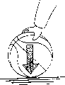
Fig. 6 shows another inflatable sport ball of the present invention, and wherein, pumping chamber 74 comprises the space between the bigger separating part 76 of carcass 12 and a rigidity, and separating part wherein is positioned at the inboard of ball, and with carcass be connected.On carcass 12 and separating part 76, be provided with duckbilled check valve 78 and 80 respectively.One spring 82 and utilizes a projection 84 on duckbilled 80 and the carcass inboard to be held in place between carcass 12 and separating part 76.Carcass 12 by Pressing pump air chamber 74 tops comes spring is compressed, and enters into ball thereby order about air from pump air chamber 74 by duckbilled 80, and the pressure in the ball is improved.When the pressure on acting on ball was released, spring forced carcass to get back to its original state, and this will be drawn into air the pumping chamber 74 by duckbilled 79 from atmosphere.Fig. 7 shows the process of carrying out pump gas by the carcass that ball is placed on the ground or on other surface and Pressing pump air chamber region is located.
Fig. 8 and 9 shows another kind of inflatable sport ball of the present invention, wherein, and in squeezable ball bubble 86 bags 88 that are accommodated in the ball.In modification shown in Figure 8, ball bubble 86 permanently is installed in the bag 88.Ball bubble 86 has a gas outlet, and this gas outlet comprises a check valve 90 that is passed into ball inside through bag 88.Ball bubble 86 also has an air inlet, and this air inlet has a check valve 92 that allows air to enter ball bubble 86 equally.The diaphragm 94 of one gas permeability is covered with ball bubble 86, and the cover plate 96 on the carcass allows near the ball bubble, thereby by pressing the pressure ball bubble downwards, can be with in the air extrusion goal.Fig. 9 is a modification that is similar to embodiment among Fig. 8, and difference is that ball bubble 86 can take out, so that operate from bag 88.Because the gas outlet of ball bubble 86 is connected by pipe 98 and check valve 90, is fine so externally operate.
Because the pressure in sport ball is owing to the rising of overinflation or temperature becomes very high, can be when traditional Aerating needle non-availability suitable a kind of mode drain pressure from ball of taking.Figure 10 illustrates so a kind of layout, its relate to one from regulation and control, adjustable pressure pressure-relief valve 100.This pressure-relief valve comprises a hole 102 of passing carcass 12, and this hole is coated with cup-shaped enclosing 104 in the inboard.Enclosing 104 has the opening 106 of a band valve seat 108.Valve 110 seals up valve seat 108, with the pressure in the protection ball.Valve rod 112 screw threads pass a dish 114, can be by the head 116 of rotary valve rod 112 in valve rod 112 upper edge axially-movables thereby coil 114.A spring 118 is provided with around valve rod 112 between dish 114 and carcass.Therefore, the head 116 by rotary valve rod 116 makes dish 114 in this valve rod upper edge axially-movable, and the pressure of regulating spring 118.The pressure of regulating spring 118 like this, thus an overvoltage in the ball will force valve to be opened and release pressure, close when required pressure reaches then.
Because the pressure in the sport ball can become too high because overinflation or temperature raise, so hope has from ball release pressure someway when not having conventional Aerating needle.Figure 10 illustrates so a kind of design, it comprises one from regulation and control, adjustable pressure-relief valve 100.This pressure-relief valve comprises a hole 102 of passing carcass 12, and the inboard in hole 102 is covered by a cap shape enclosing 104.Enclosing 104 has the opening 106 of a band valve seat 108.Valve 110 roof pressure hermetically valve seat 108, to keep the pressure in the ball.Valve rod 112 revolves from a dish 114 and passes, thereby can make dish 114 axially-movables on valve rod 112 by the head 116 of rotary valve rod 112.One spring 118 is between dish 114 and carcass, and it is around valve rod 112.Therefore, the head 116 by rotary valve rod 112 can make dish 114 in the axially-movable of valve rod upper edge, and the pressure of regulating spring 118.Come the pressure of regulating spring 118 like this: the overvoltage in the ball will force valve to be opened, thereby release pressure is closed valve when reaching required pressure then.
Claims (9)
Applications Claiming Priority (2)
| Application Number | Priority Date | Filing Date | Title |
|---|---|---|---|
| US09/594,180 US6450906B1 (en) | 1999-10-14 | 2000-06-14 | Self contained sport ball inflation mechanism |
| US09/594,180 | 2000-06-14 |
Publications (2)
| Publication Number | Publication Date |
|---|---|
| CN1447707A CN1447707A (en) | 2003-10-08 |
| CN1274376C true CN1274376C (en) | 2006-09-13 |
Family
ID=24377854
Family Applications (1)
| Application Number | Title | Priority Date | Filing Date |
|---|---|---|---|
| CNB018141471A Expired - Fee Related CN1274376C (en) | 2000-06-14 | 2001-06-13 | Self-Contained Sports Ball Inflator |
Country Status (9)
| Country | Link |
|---|---|
| US (1) | US6450906B1 (en) |
| EP (1) | EP1289607A4 (en) |
| JP (1) | JP2004503306A (en) |
| KR (1) | KR20030046340A (en) |
| CN (1) | CN1274376C (en) |
| AU (2) | AU2001268379B2 (en) |
| CA (1) | CA2411265A1 (en) |
| MX (1) | MXPA02012373A (en) |
| WO (1) | WO2001095982A1 (en) |
Families Citing this family (29)
| Publication number | Priority date | Publication date | Assignee | Title |
|---|---|---|---|---|
| US6887173B2 (en) * | 1999-10-14 | 2005-05-03 | Russell Asset Management, Inc. | Inflatable articles with self-contained inflation mechanism |
| US6916262B2 (en) | 1999-10-14 | 2005-07-12 | Russell Asset Management, Inc. | Sport ball with energy absorbing foam at varying locations |
| US6935977B2 (en) * | 1999-10-14 | 2005-08-30 | Russell Asset Management, Inc. | Sport ball with pump having pressure relief and/or pressure indication capability |
| RU2005107722A (en) * | 2002-08-21 | 2005-08-20 | ЭсДжиДжи ПЕЙТЕНТС ЛЛС (US) | SPORTS BALL CONTAINING INSIDE IT WITH A PUMPING MECHANISM WITH PRESSURE INDICATION |
| US7278937B2 (en) * | 2002-12-20 | 2007-10-09 | Russell Corporation | Sport ball with self-contained inflation mechanism having pressure relief and indication capability |
| CA2484590A1 (en) * | 2002-12-20 | 2004-07-15 | Sgg Patents Llc | Sport ball with self-contained inflation mechanism having pressure relief capability |
| US7503861B2 (en) * | 2004-01-09 | 2009-03-17 | Russell Asset Management, Inc. | Sportsball and method of manufacturing same |
| USD519174S1 (en) | 2004-01-09 | 2006-04-18 | Russell Asset Management, Inc. | Sportsball |
| USD518862S1 (en) | 2004-01-10 | 2006-04-11 | Russell Asset Management, Inc. | Sportsball |
| USD516642S1 (en) | 2004-01-10 | 2006-03-07 | Russell Asset Management, Inc. | Sportsball |
| IL161159A0 (en) * | 2004-03-29 | 2004-08-31 | Cyclo Science Ltd | Tourniquet |
| CN1323731C (en) * | 2004-06-09 | 2007-07-04 | 唐雅芳 | The liner of the sports ball and the sports ball |
| US7175553B2 (en) * | 2005-01-13 | 2007-02-13 | Russell Corporation | Sport ball with self-contained inflation mechanism and pressure indicator |
| US20060205544A1 (en) * | 2005-03-08 | 2006-09-14 | Polyworks, Inc. | Dynamic toy with inflatable bladder |
| USD539858S1 (en) | 2006-02-21 | 2007-04-03 | Russell Asset Management, Inc. | Basketball |
| USD544931S1 (en) | 2006-02-21 | 2007-06-19 | Russell Corporation | Basketball |
| USD532841S1 (en) | 2006-02-21 | 2006-11-28 | Russell Asset Management, Inc. | Basketball |
| US7827704B2 (en) | 2006-02-28 | 2010-11-09 | Polyworks, Incorporated | Methods of making polymeric articles and polymeric articles formed thereby |
| FR2904231B1 (en) | 2006-07-25 | 2008-10-17 | Commissariat Energie Atomique | SPORTS BALL WITH AUTOMATIC INFLATION MEANS AND METHOD FOR MANAGING THE INTERNAL PRESSURE OF SUCH A BALLOON |
| US20080199335A1 (en) * | 2007-02-20 | 2008-08-21 | Melatti Livio R | Vacuum storage container with integrated pump |
| WO2008128206A1 (en) * | 2007-04-13 | 2008-10-23 | Polyworks, Inc. | Cushioning medallions, methods of making and methods of using |
| US8871328B2 (en) | 2007-04-13 | 2014-10-28 | Daniel M. Wyner | Impact and vibration absorbing body-contacting medallions, methods of using and methods of making |
| MX336122B (en) | 2008-04-14 | 2016-01-08 | Polyworks Inc | Deep draw method of making impact and vibration absorbing articles and the articles formed thereby. |
| US20090325739A1 (en) * | 2008-06-25 | 2009-12-31 | Gold Robert S | Intelligent basketball |
| US20120244969A1 (en) | 2011-03-25 | 2012-09-27 | May Patents Ltd. | System and Method for a Motion Sensing Device |
| US10465809B2 (en) | 2013-02-22 | 2019-11-05 | Nsi International, Inc. | Valve assembly for expandable bladder and method of manufacturing the same |
| DE212014000054U1 (en) | 2013-02-22 | 2015-12-10 | Nsi International, Inc. | Valve arrangement for inflatable bladder |
| ITBO20130468A1 (en) * | 2013-08-30 | 2015-03-01 | Trial S R L | GINNICO DEVICE |
| US20250161836A1 (en) * | 2023-11-16 | 2025-05-22 | Foluck International Co.,Ltd. | Inflatable toy |
Family Cites Families (7)
| Publication number | Priority date | Publication date | Assignee | Title |
|---|---|---|---|---|
| US602294A (en) | 1898-04-12 | Island | ||
| US2698028A (en) | 1949-07-14 | 1954-12-28 | Samuel W Lee | Valve for self-contained inflatable articles |
| US3020673A (en) | 1956-02-10 | 1962-02-13 | Cooke Helen | Expanding toy |
| US3119617A (en) * | 1960-12-19 | 1964-01-28 | Bernard Kaufman C | Self inflating ball |
| JPS51147553A (en) * | 1975-06-13 | 1976-12-17 | Kiyokutou Purasuchitsuku Kagak | Method of molding thermoplasic plastics |
| US5098095A (en) | 1991-05-06 | 1992-03-24 | Weiss Twice Toys, Inc. | Pump ball |
| US5238244A (en) * | 1991-05-06 | 1993-08-24 | Weiss Twice Toys, Inc. | Pump ball |
-
2000
- 2000-06-14 US US09/594,180 patent/US6450906B1/en not_active Expired - Fee Related
-
2001
- 2001-06-13 JP JP2002510156A patent/JP2004503306A/en active Pending
- 2001-06-13 KR KR1020027017077A patent/KR20030046340A/en not_active Withdrawn
- 2001-06-13 CN CNB018141471A patent/CN1274376C/en not_active Expired - Fee Related
- 2001-06-13 EP EP01946312A patent/EP1289607A4/en not_active Withdrawn
- 2001-06-13 WO PCT/US2001/018995 patent/WO2001095982A1/en not_active Ceased
- 2001-06-13 AU AU2001268379A patent/AU2001268379B2/en not_active Expired
- 2001-06-13 CA CA002411265A patent/CA2411265A1/en not_active Abandoned
- 2001-06-13 AU AU6837901A patent/AU6837901A/en active Pending
- 2001-06-13 MX MXPA02012373A patent/MXPA02012373A/en unknown
Also Published As
| Publication number | Publication date |
|---|---|
| AU2001268379B2 (en) | 2006-02-09 |
| WO2001095982A1 (en) | 2001-12-20 |
| EP1289607A1 (en) | 2003-03-12 |
| CA2411265A1 (en) | 2001-12-20 |
| MXPA02012373A (en) | 2004-01-26 |
| AU6837901A (en) | 2001-12-24 |
| KR20030046340A (en) | 2003-06-12 |
| CN1447707A (en) | 2003-10-08 |
| US6450906B1 (en) | 2002-09-17 |
| EP1289607A4 (en) | 2004-11-17 |
| JP2004503306A (en) | 2004-02-05 |
Similar Documents
| Publication | Publication Date | Title |
|---|---|---|
| CN1274376C (en) | Self-Contained Sports Ball Inflator | |
| CN1230230C (en) | Self-contained sport ball inflation mechanism | |
| US6422960B1 (en) | Self contained sport ball inflation mechanism | |
| AU2001268379A1 (en) | Self contained sport ball inflation mechanism | |
| US6887173B2 (en) | Inflatable articles with self-contained inflation mechanism | |
| US6287225B1 (en) | Self contained sport ball inflation mechanism | |
| JP2005506862A (en) | Pneumatic inflation device completely contained within the sole | |
| USRE37983E1 (en) | Air pump | |
| AU2001251624B2 (en) | Self contained sport ball inflation pump | |
| AU2001251624A1 (en) | Self contained sport ball inflation pump | |
| US6935977B2 (en) | Sport ball with pump having pressure relief and/or pressure indication capability | |
| AU2002324593A1 (en) | Inflatable articles with self-contained inflation mechanism | |
| HK1056130B (en) | Self-contained sport ball inflation mechanism |
Legal Events
| Date | Code | Title | Description |
|---|---|---|---|
| C06 | Publication | ||
| PB01 | Publication | ||
| C10 | Entry into substantive examination | ||
| SE01 | Entry into force of request for substantive examination | ||
| C14 | Grant of patent or utility model | ||
| GR01 | Patent grant | ||
| C17 | Cessation of patent right | ||
| CF01 | Termination of patent right due to non-payment of annual fee |
Granted publication date: 20060913 Termination date: 20100613 |