The description of preferred embodiment
High-pressure discharge lamp of the present invention based on metal halid lamp (it be high-pressure discharge lamp a type) is described with reference to the accompanying drawings.
(first embodiment)
Fig. 1 is the part sectioned view according to metal halid lamp 21 of the present invention.
Metal halid lamp (after this abbreviating " lamp " as) 21 has the wattage of 150 watts specified lamp, and is used in common room lighting.
As shown in Figure 1, lamp 21 has following structure.The luminescence unit 2 that has comprised arc lamp tube 1 is positioned in the outer bulb 22, and bulb 22 is equipped with pedestal 23.In addition, externally in the bulb 22, provide the quartz burner 24 of shielding,, be used to prevent that outer bulb 22 from damaging so that surround arc lamp tube 1.Outer bulb 22 is made by quartz glass or Bohemian glass.Externally gassy in the bulb 22 mainly is a neon.
Fig. 2 is the longitdinal cross-section diagram of luminescence unit 2.
As shown in the figure, luminescence unit 2 comprises arc lamp tube 1, and it is made up of king light duct member 3 and tubule parts 4 and 5 (they extend from the two ends of king light duct member 3 respectively). Tubule parts 4 and 5 have less diameter compared with king light duct member 3.King light duct member 3 and tubule parts 4 and 5 are made by semi-transparent polycrystal alum clay ceramic material, and it has about 1200 ℃ heat resistance.In king light duct member 3, form discharge space.Tubule parts 4 and 5 hold on the shaft portion (tungsten electrode bar 12 and 13) of tungsten electrode 10 and 11 respectively.And, in arc lamp tube 1, include: (a) by metal halide (DyI
3+ TmI
3+ HoI
3+ the luminescent material 20 TlI+NaI) formed is (b) as the mercury of buffer gas with (c) play the argon of the rare gas of startup booster action.
Tungsten electrode (after this abbreviating " electrode " as) 10 and 11 is respectively by tungsten electrode bar (after this abbreviating " electrode bar " as) 12 and 13, and tungsten coil 14 and 15 (being provided with round an end of electrode bar 12 and 13) is formed.
Electrode 10 and 11 is held on by molybdenum capillary 6 and 7 by tubule parts 4 and 5 respectively.Particularly, pass molybdenum capillary 6 and 7 as the electrode bar 12 and 13 of the axial members of electrode 10 and 11, the latter plays the effect of electrode sleeve.Molybdenum capillary 6 and 7 is made by molybdenum actually, and molybdenum is the metal of anti-halogenation.Here should be pointed out that electrode bar 12 and 13 and molybdenum capillary 6 and 7 by laser welding near the outlet of tubule parts 4 and 5 and by bonding (sealing) airtightly (so that formation be sealing adhesive parts 18 and 19) together.In addition, tungsten coil 14 and 15 is partly melted and is glued on electrode bar 12 and 13.Here should be pointed out that also that electrode bar 12 and 13 is used as outside lead from be sealing adhesive parts 18 and 19 parts of extending.
Molybdenum capillary 6 and 7 and tubule parts 4 and 5 by adhesive 8 and 9 sealed according to technology (after this being called " metallization Sealing Technology ") by metallized sealing.The metallization Sealing Technology realizes by chemical bonding, so, can form bonded areas with super adhesion strength, to compare with the sintering Sealing Technology, it and luminescent material less react.
Fig. 3 is the local amplification sectional view by the seal member of adhesive 8 sealings.This figure shows that at length wherein tubule parts 4 (alum clay pottery) and molybdenum capillary 6 (molybdenum) are by adhesive 8 bonded (sealing) state together.Here should be pointed out that the adhesive 9 that is used for sealing other seal members is identical with adhesive 8, so, adhesive 8 is only described below.
As shown in the figure, adhesive 8 is made up of main stor(e)y 81 and interface glassy layer 82.Main stor(e)y 81 contacts with molybdenum capillary 6.Interface glassy layer 82 is by Dy
2O
3-Al
2O
3Glass is made, and is provided on the interface between tubule parts 4 and the main stor(e)y 81.Main stor(e)y 81 is made by the metallic (such as the molybdenum particle) of sintering, and is made up of cellular structure 83 with open pore and the glass phase 84 that is perfused in the open pore.Glass phase 84 is Dy by its main component
2O
3-Al
2O
3Dy
2O
3-Al
2O
3Glass mixture is made.Here should be pointed out that Dy
2O
3-Al
2O
3Glass mixture can comprise on a small quantity such as La
2O
3And Y
2O
3Composition.According to the adhesive 8 that as above makes up, the glass mixture that is poured in the open pore is used as a kind of buffer, so, can improve thermal shock resistance.More specifically, above adhesive 8 is characterised in that: it comprises metal with the such sintering of open pore and the such glass mixture that is perfused in open pore.Here should be pointed out that adhesive 8, be used for the manufacture method of adhesive 8 and use the adhesive method of adhesive 8 all to be described in detail, therefore, in the present technique explanation, no longer be described at day patent application No.2001-58882 of the present disclosure.
With reference to Fig. 2, provide the size of the basic element of character of luminescence unit 2 below with above-mentioned structure.
The maximum inner diameter of king light duct member " φ i ": 10.7[mm]
The length " Lo " that the inside of king light duct member is total: 15.4[mm]
Distance between electrodes " Le ": 10.7[mm]
Total length " La " of tubule parts: 10.7[mm]
The overall diameter of tubule parts: 3.2[mm]
The interior diameter of tubule parts: 1.3[mm]
Molybdenum overall diameter capillaceous: 1.2[mm]
Molybdenum thickness capillaceous: 0.10[mm]
The line footpath of electrode bar: 0.5[mm]
Here should be pointed out that arc lamp tube 1 is 3.5mm by using metallization Sealing Technology sealed parts in hermetic unit along the length " Lf " on the fluorescent tube direction of principal axis (vertical direction on the figure) (after this being called " metallization seal length ").Metallization seal length " Lf " is set to for guaranteeing the needed numerical value of good hermetic seal.In addition, the tube wall of arc lamp tube 1 load " we " is set to about 27W/cm
2
In this lamp 21, spacing distance " Lm ", be along the axial distance of fluorescent tube between the end 61 of the top of discharge space edge tungsten electrode 10 and molybdenum capillary 6, and between the end 71 of the top of discharge space edge tungsten electrode 11 and molybdenum capillary 7 along the axial distance of fluorescent tube, be set to 5.5mm.Describe below and why will be set to the reason of such numerical value apart from " Lm ".
In order to improve the luminous efficiency of using the metallization Sealing Technology, the inventor of present patent application makes a lamp by experiment, and its tubule parts 4 and 5 length " La " are set to be short to 4.0mm.The spacing distance of the lamp of this experiment " Lm " is 2.5mm.
The inventor carries out life test to this experimental lamps then, and 0.5 hour shutoff cycle is followed in the connection cycle back of using 5.5 hours.The initial luminous efficiency of this experimental lamps is 97lm/W, is 90lm/W and adopt the initial luminous efficiency of traditional lamp of sintering Sealing Technology, this means the lamp of experiment hereto, can reach the raising of about 8% expection.In addition, it approximately is 92 that the general colour of experimental lamps presents index " Ra ", approximately is 90 and adopt the general colour of traditional lamp of sintering Sealing Technology to present index " Ra ", and this also means experimental lamps hereto, is improved.In this test, also measured the temperature " Tc " of the end " C " of king light duct member 3.The temperature of experimental lamps " Tc " is compared with for high about 250 ℃ of the temperature of the traditional lamp that adopts the sintering Sealing Technology.
These test results can be explained as follows.For experimental lamps, thermal losses is reduced by shortening the tubule parts.Because less thermal losses, luminous efficiency is enhanced.And mainly the vapour pressure of the luminescent material of being made by metal halide 20 is increased.Because the vapour pressure that increases, general colour presents index " Ra " and is enhanced.
Yet, when beginning from this life test, observe the inner surface blackening of king light duct member 3 through 500 hours.At this moment, its luminous flux be begun to pass through from this life test 100 hours measured value about 70%.In order to draw the reason of this phenomenon, the inventor of present patent application investigates the discharge condition when the startup of lamp, finds that discharge is to begin from the molybdenum capillary 6 and 7 that is used as conductor.More specifically, because at the end 61 of discharge space edge molybdenum capillary 6 and 7 and the discharge space 25 of 71 too close experimental lamps, heat is outwards selected by the cross section of molybdenum capillary 6 and 7.Because this point carries out the transition to arc discharge meeting cost long time.Carrying out the transition to this long time durations of arc discharge, from the molybdenum capillary 6 of discharge space edge and 7 end 61 and 71 beginning glow discharges, and the sputter during glow discharge makes molybdenum be spread and be attached to the inner surface of king light pipe 3, makes the inner surface blackening of king light pipe 3 thus.This causes, and luminous flux is worsened in the effective working life of lamp.
In order to overcome the above problems, the present inventor has tested the whole bag of tricks, find at last end 61 and 71 when molybdenum capillary 6 and 7 be placed with discharge space 25 along the fluorescent tube direction of principal axis spaced apart predetermined apart from the time, can end 61 and the 71 startup glow discharges from molybdenum capillary 6 and 7 in discharge space edge.More specifically, the inventor tests, and from the size of the parts of lamp listed above, extends the length " La " of tubule parts 4 and 5, does not change metallization seal length " Lf " so that increase spacing distance " Lm ".In fact the inventor has prepared a plurality of fluorescent tubes, and its length " La " is set to each numerical value, to longer, and carries out above-mentioned life test for the lamp of each preparation from 4.0mm (" Lm " is 2.5mm).
Fig. 4 shows figure resulting from life test, the relation between the numerical value of " Lm " and the maintenance of the luminous flux after the 500 hours factor.
As what see from figure, luminous flux keeps the factor to increase with spacing distance " Lm ", this means that blackening phenomena is reduced when spacing distance " Lm " increases.These test results prove, when spacing distance " Lm " is 4.3mm or when bigger, do not produce glow discharge fully from the end 61 and 71 of molybdenum capillary 6 and 7.Keeping the factor at the luminous flux of the lamp of measuring after 500 hours at spacing distance " Lm " when being 4.3mm is 93% of the numerical value measured after 100 hours.Keep the factor for the luminous flux of this lamp of spacing distance " Lm " when being 4.3mm, keep the factor compared with the luminous flux of first experimental lamps (its spacing distance " Lm " is 2.5mm), then be about its 70%, this shows and is significantly improved.And after 6000 hours, it is 75% that the luminous flux of this lamp keeps the factor.In addition, the initial luminous efficiency of this lamp is 94.5lm/W, compares with traditional lamp, shows 5% the improvement of having an appointment.So these test results prove that its spacing distance " Lm " is that this lamp of 4.3mm does not have to produce because the luminous colour that the inner surface blackening of king light duct member 3 causes changes the defective that causes, so this lamp also reaches the purpose of improved luminous efficiency.
In a word, when spacing distance " Lm " be 4.3mm or more hour 150 watts of lamps show improved luminous efficiency, but it is subjected to the influence of blackening phenomena.
The present inventor also carries out same life experiment for the lamp of the various wattages that are different from 150 watts of lamps, so that draw the minimum value that still can stop for the spacing distance " Lm " of the blackening phenomena of each lamp with various wattages.For 20W, 35W, 70W, 100W, the lamp of 250W and 400W, this minimum value of spacing distance " Lm " is found to be 2.6mm respectively, 2.9mm, 3.3mm, 3.7mm, 5.4mm, and 7.2mm.
Fig. 5 shows figure that obtain from life test, the relation between the minimum value of the wattage of lamp and " Lm ".
As what see, can be painted as straight line 28 basically for the minimum value of the spacing distance of the wattage [W] of each lamp from figure.So, the wattage " P " of the minimum value of spacing distance " Lm " and lamp concern expression can be basically by using linear function " Lm=0.012P+2.5[mm] " to be write out.
This expression shows that the minimum value of spacing distance " Lm " increases with the wattage of lamp.This can be explained as follows.For high-pressure discharge lamp, such as metal halid lamp, when the wattage of lamp more hour, electrode distance " Le " is short more usually, vice versa.Short electrode distance " Le " mean from the higher probability of the top startup arc discharge of tungsten electrode.In other words, long electrode distance " Le " mean the higher probability that starts glow discharge.For little wattage, electrode distance " Le " be short, so glow discharge is not activated from the end 61 and 71 of discharge space edge molybdenum capillary 6 and 7 mostly, even spacing distance " Lm " to be set to also be like this very in short-term.On the other hand, for the lamp with bigger wattage, electrode distance " Le " be long, so glow discharge is produced mostly, unless spacing distance " Lm " be set to long.
As mentioned above, for each lamp with various wattages, blackening phenomena can be set to be avoided by the such numerical value that uses above expression to calculate as minimum value by spacing distance " Lm ".On the other hand, if spacing distance " Lm " is set to larger than necessary numerical value, then owing to thermal losses, luminous efficiency can be worsened unfriendly.So, preferably spacing distance " Lm " is set to consider various factors (such as size and the luminous efficiency in the effective life of lamp and the luminous flux maintenance factor of lamp) and definite optimum value.As an example, preferably spacing distance " Lm " is set to the numerical value selected from the diagonal shadow region of Fig. 5.
The present inventor has prepared 150 watts lamp, and its spacing distance " Lm " is set to 5.5mm, and length " La " is set to 7.0mm.The inventor measures the characteristic of the initial lamp of lamp then, that is, initial luminous efficiency and general colour present index, and lamp is carried out above life experiment.According to test result, initial luminous efficiency is that to present index be 91.4 for 95lm/W and general colour.Begin through 6000 hours from life test before, blackening phenomena does not appear.And, owing to comprise the improved thermal shock resistance that the adhesive 8 and 9 of glass mixture causes, begin through 6000 hours from life test before, the damage and the leakage of tubule parts 4 and 5 do not appear, and the change of glow color.
According to above-mentioned present embodiment, spacing distance " Lm " is the distance between the top of tungsten electrode and discharge space edge molybdenum end capillaceous, be arranged on optimum value to it according to above expression.By doing like this, during the effective working life of lamp, the blackening phenomena of the inner surface of arc lamp tube can be prevented from, and produces the effect that improves luminous efficiency thus.
Here should be pointed out that the application of above relational expression of the minimum value of wattage [W] for lamp and spacing distance " Lm " [mm], the wattage that should not be only limited to lamp is 400W and littler lamp.Though not shown on Fig. 5, above relational expression can be applied to the wattage of lamp greater than 400W, for example, the lamp of 1KW and the lamp of 2KW.
(second embodiment)
Only be that according to the metal halid lamp of present embodiment and difference the element (after this being called " molybdenum coil ") that is made into as the metal of anti-halogenation by molybdenum is looped around on electrode bar 12 and 13 according to the metal halid lamp of first embodiment.Present embodiment is described below, only concentrates on the difference of it and first embodiment.Here, with according to the parts of the metal halid lamp of first embodiment identical, according to the parts of the metal halid lamp of present embodiment, on figure, be given identical reference number, and do not describe in the present embodiment.
Fig. 6 shows the structure according to the luminescence unit of present embodiment.
As shown in the figure, molybdenum coil 32 surrounding electric poles rod 12 is provided with, and molybdenum coil 33 surrounding electric poles rod 13 is provided with.Like this, the slit that between tungsten electrode axle and tubule parts, forms, the slit that will and form between tungsten electrode axle and molybdenum capillary forms bridge joint, to be used for following improvement effect.
By such structure: wherein tubule parts 4 and 5 are provided at the two ends (this is as in the present embodiment) of king light duct member 3, and the luminescent material 20 that is enclosed in the arc lamp tube 1 mainly is present in the king light duct member 3 with liquid form.Yet, a part of luminescent material 20 flow to tubule parts 4 and 5 and molybdenum capillary 6 and 7 in.Tubule parts 4 and 5 and molybdenum capillary 6 and 7 in the accumulation a part of luminescent material 20 be not used in original luminous purpose.In order to obtain stable glow color, so, need be inclusive in the arc lamp tube 1 compared with the luminescent material of the needed bigger amount of emission light, so that compensate such loss.This means and to use compared with the needed more substantial luminescent material of emission light.
Thereby as by reduce to flow to tubule parts 4 and 5 and molybdenum capillary 6 and 7 in the quantity of such part reduce to be inclusive in a method of the total amount of the luminescent material in the arc lamp tube 1, by the metal element of anti-halogenation be provided to narrow down surrounding electric poles rod 12 spaces that form and excellent 13 spaces that form of surrounding electric poles.Particularly, these elements are provided to bridge joint between electrode bar 12 and the tubule the parts 4 and slit between electrode bar 12 and molybdenum capillary 6, and between electrode bar 13 and the tubule the parts 5 and slit between electrode bar 13 and molybdenum capillary 7.Such element can block luminescent material and flow in these slits.If coil part is used as the element that is used for these slits of bridge joint, then when comparing when using tube element, the area of section of element is less relatively, so heat is difficult to select by coil part.In this case, so such problem that cost carries out the transition to arc discharge for a long time can not occur.
Carried out life test for such lamp with above-mentioned structure.According to test result, almost do not observe the influence that causes by sputter, and do not have to occur because the blackening phenomena that the diffusion of molybdenum causes.And, be inclusive in the total amount of the luminescent material in the arc lamp tube 1 of such lamp, compared with the luminescent material total amount in the lamp that does not have molybdenum coil 32 and 33, approximately want little by 30%.
Here, coil part can be only by being ready wire-wound at each electrode bar 12 and 13, but it is very difficult making tube element, because tube element should accurately be made, so that its internal diameter is greater than the external diameter of each electrode bar 12 and 13, and its external diameter is less than the internal diameter of each molybdenum capillary 6 and 7.
In order to stop luminescent material to flow to tubule parts 4 and 5 etc. effectively, preferably the molybdenum coil 32 and 33 of the whole area of surrounding electric poles rod 12 and 13 is inserted in (being placed on) tubule parts 4 and 5, as shown in the figure.
In addition, when the end 321 and 331 in discharge space edge molybdenum coil 32 and 33 be placed on along the fluorescent tube direction of principal axis (a) discharge space edge molybdenum capillary 6 and 7 end 61 and 71 and (b) between discharge space edge tubule parts 4 and 5 the end 41 and 51 Anywhere the time, can produce and reduce to flow to molybdenum capillary 6 and 7 and even flow to the effect of the luminescent material amount of tubule parts 4 and 5.
And, when molybdenum coil only partly when being placed on electrode bar 12 in molybdenum capillary 6 and 7 and 13 area, do not compare with the situation of molybdenum coil wherein is provided, can produce the effect of the total amount that reduces to be inclusive in the luminescent material in the king light pipe 1 to a certain extent yet.
Here should be understood that, when laser welding, the base portion end of molybdenum coil 32 (end opposite with discharge space 25) welds mutually with the airtight adhesive segment 18 in the molybdenum capillary 6 and is fixing, and the base portion of molybdenum coil 33 terminal by with molybdenum capillary 7 in airtight adhesive segment 19 weld mutually and fixing.
Though present embodiment has been described the situation that the element of wherein being made by molybdenum is used as the wound element on the electrode bar, can be used as wound element by metal any element of anti-halogenation.Certainly, wound element should have such diameter, and this diameter makes it can be placed in the slit that forms between the inner surface of the surface of each electrode bar 12 and 13 and each molybdenum capillary 6 and 7.In order to make the luminescent material amount flow in each molybdenum capillary 6 and 7 minimize, preferably make electrode bar 12 and 13 and the surface of molybdenum capillary 6 and 7 between the slit that forms minimize.So preferably, wound element has such diameter, this diameter make to allow the surface of the wound element on electrode bar 12 and 13 contact with the inner surface of molybdenum capillary 6 and 7.In addition, the line-spacing of wound element is to be determined according to the degree that reduces the needs of the luminescent material amount in each molybdenum capillary 6 and 7 that flows to.
(the 3rd embodiment)
As shown in Figure 7, have a kind of like this structure according to the luminescence unit 50 of present embodiment, the startup auxiliary conductor of wherein knowing 51 is by on the fixing arc lamp tube 1 in a second embodiment additionally.
As shown in the figure, the startup auxiliary conductor 51 that is fixed on the arc lamp tube 1 is made by wound element, and a link 511 that starts auxiliary conductor 51 is looped around on the tubule parts 4, and another link 512 that starts auxiliary conductor 51 is looped around on the tubule parts 5.
The coiling position that can supply link 511 to be looped around tubule parts 4 places has the distance of 2mm towards discharge space one side along the end 61 that the fluorescent tube direction of principal axis leaves discharge space place molybdenum capillary 6.The coiling position that can supply link 512 to be looped around tubule parts 5 places also has the distance of 2mm towards discharge space one side along the end 71 that the fluorescent tube direction of principal axis leaves discharge space place molybdenum capillary 7.
This is owing to following reason.When starting auxiliary conductor and be attached to arc lamp tube, when starting, lamp begins to discharge from the position of approaching to start auxiliary conductor most.Suppose that the link 511 that starts auxiliary conductor 51 is looped around on the position of tubule parts 4, represents with " A " on figure.In this case, when starting, lamp between link 511 and molybdenum capillary 6, produces glow discharge.Arc discharge can cause the blackening phenomena of arc lamp tube.
In order to begin discharge from the molybdenum coil 33 that approaches most to start auxiliary conductor 51 and 34 position, promptly, in order to forbid beginning arc discharge from molybdenum capillary 6 and 7, start auxiliary conductor 51 and will be attached, so that it does not cause between link 511 and the molybdenum capillary 6 and the glow discharge between link 512 and molybdenum capillary 7 in such position.More specifically, the link 511 that starts auxiliary conductor 51 will be wrapped between the end 321 of the end 61 that is in discharge space edge molybdenum capillary 6 on the tubule parts 4 and discharge space edge molybdenum coil 32, along the axial position of fluorescent tube, and the link 512 of startup auxiliary conductor 51 will be wrapped between the end 331 of the end 71 that is in discharge space edge molybdenum capillary 7 on the tubule parts 5 and discharge space edge molybdenum coil 33, along the axial position of fluorescent tube.
In this case, because molybdenum coil 32 and 33 is coil parts, aforesaid, because the diffusion of the molybdenum that causes of sputter is rare.So, start the effect that auxiliary conductor can cause the startup character of improving lamp.Here, the discharge when lamp starts is close to discharge space 25 and produces, and then the startability of lamp is better at this moment.Consider this point, the winding position that best link 511 and 512 is wrapped on tubule parts 4 and 5 will approach discharge space 25 as far as possible.
Here should be understood that, though present embodiment has been described the situation that the link 511 that wherein starts auxiliary conductor 51 twines tubule parts 4 and starts the link 512 winding tubule parts 5 of auxiliary conductor 51, yet as long as can realize starting the function of auxiliary conductor 51, the present invention should not be limited to such situation.For example, have only link 511 to twine tubule parts 4, and link 512 can be connected to airtight adhesive segment 19.Here should be pointed out that also that starting auxiliary conductor 51 can be made by lead elements and production method thereof, but it can be made also by thin sheet element.
(the 4th embodiment)
Though first to the 3rd above embodiment has described the configuration example that can stop the arc lamp tube blackening, present embodiment is described and can be stoped the configuration example that produces cracking and glow color change.
Fig. 8 is the longitdinal cross-section diagram according to the luminescence unit 200 of present embodiment.Luminescence unit 200 have basically with according to the identical structure of the luminescence unit 2 of first embodiment, its difference is that tubule parts 4 and 5 are replaced by tubule parts 201 and 202, and molybdenum coil 203 and 204 is wound round being placed on electrode bar 12 in tubule parts 4 and 5 and 13 zone.In addition, tubule parts 201 are different with tubule parts 4 and 5 among first embodiment on the length of fluorescent tube direction of principal axis (describing later on) with 202.Here, molybdenum coil 203 and 204 is provided to make the spaces in tubule parts 201 and 202 to minimize, and they are identical with molybdenum coil 32 and 33 among second embodiment basically.Here, with according to the parts of the luminescence unit of first embodiment identical, be given identical reference number according to the parts of the luminescence unit 200 of present embodiment, and be not described in the present embodiment.
For the such luminescence unit 200 that makes up as illustrated in fig. 8, to be done hour when the thermal capacity of tubule parts 201 and 202, luminous efficiency is further improved.Tubule parts 201 and 202 thermal capacity can increase or reduce the method or the expansion of total length of each tubule parts 201 and 202 or the method that reduces the external diameter of each tubule parts 201 and 202 is conditioned by using.The inventor of present patent application adopts the former method that increases or reduce total length of each tubule parts 201 and 202.The inventor at first makes (by means of experiment) metal halid lamp, and its each tubule parts 201 and total length of 202 are extremely short (that is, 4mm), and this experimental lamps to be carried out luminous test.
According to test result, the luminous efficiency of experimental lamps is 97lm/W, with according to the manufacturing of sintering Sealing Technology, with experimental lamps have identical specified lamp wattage metal halid lamp 90lm/W luminous efficiency (after this be called " and for the contrast lamp ") compare, shown about 8% improvement.The luminous efficiency of experimental lamps be with the expection the same high.In addition, it is 92 that the general colour of experimental lamps presents index " Ra ", and 90 the general colour that it is higher than for the lamp of reference presents index " Ra ".Here, the surface temperature of the king light pipe end " C " of experimental lamps (it is an end of king light duct member and is hithermost position in the king light duct member) is about 990 ℃ when stabilized illumination.On the other hand, the surface temperature of the king light pipe end " C " of the lamp of confession reference is about 740 ℃ when stabilized illumination.This means, the surface temperature of the king light pipe end " C " of experimental lamps, the lamp compared with for reference will exceed 250 ℃ more than.These test results disclose: the luminous efficiency of experimental lamps and general colour present index " Ra " with respect to the improvement for the lamp of reference, and can be considered to is that the effect of vapour pressure of increase of the luminescent material made by metal halide causes basically.
Here, the inventor of present patent application carries out life test to above experimental lamps, and 0.5 hour shutoff cycle is followed in the connection cycle back of using 5.5 hours.When after test beginning through about 500 hours, corresponding to the tubule parts 210 by using the sealed sealing area (bonded areas) of metallization Sealing Technology and 202, produce the cracking damage near near discharge space terminal.Cracking damage generation rate (defective generation rate) is 27% during 6000 hours specified useful life.These test results have disclosed following content.Though adhesive 8 and 9 comprises glass phase (glass mixture) as buffering, if they are placed and approach very much wherein to exist the discharge space of thermal source and be exposed under the too high temperature, then above problem can occur.More specifically, (a) adhesive 8 and 9 and the difference that (b) is used for the linear expansion coefficient between the translucent ceramic material of tubule parts and 202 cause the cracking of tubule parts 201 and 202.
In addition, during above specified useful life, the leakage slowly of hermetic unit not taking place, but observes the change of glow color at least.Glow color change rate (defective generation rate) is about 4%.Then, the present inventor is by tight examination, observes the hermetic unit of the experimental lamps that its glow color changed.At an end of the hermetic unit that more approaches discharge space, find to be comprised in the Dy in adhesive 8 and 9
2O
3-Al
2O
3Glass by luminescent material 20 (particularly, by NaI, DyI
3, and TmI
3) etch.The change of glow color is attributable to be released to the Dy of the etch of discharge space
2O
3-Al
2O
3Glass.Here, above etch phenomenon is placed too close owing to adhesive 8 and 9 once more and wherein has the discharge space of thermal source and be exposed to too high temperature.
Then, the present inventor has made some experimental lamps, and the metallization seal length " Lf " of each lamp is identical, and total length " La " of tubule is (non-tight length " Lx " as shown in Figure 8 increases progressively gradually) that changes.The inventor carries out above test to each these experimental lamps.By increasing non-tight length " Lx ", the end 62 and 72 (after this being called " metallization seal end ") of the close discharge space of the bonded areas that is formed by adhesive 8 and 9 is placed with away from the discharge space that wherein has thermal source.By doing like this, so the temperature of metallization seal end can be lowered.
Be difficult to directly measure the temperature of metallization seal end.So, be used to assess in the temperature of locating corresponding to the surface point " P " of tubule parts of metallization sealed end (after this being called " hull-skin temperature of metallization seal end ").Hull-skin temperature be when stabilized illumination by use have ± bolometer of 3.0% certainty of measurement measures.
Fig. 9 and 10 illustrates test result.Fig. 9 is hull-skin temperature and because the figure of the relation between the defective generation ratio that the glow color change causes that is presented at the metallization sealed end.Figure 10 is hull-skin temperature and because the figure of the relation between the defective generation ratio that the cracking damage causes in the tubule parts that is presented at the metallization sealed end.
As what see, when the hull-skin temperature of metallization sealed end is 950 ℃ or when lower, do not take place because glow color changes the defective that causes produces from Fig. 9.In other words, by the hull-skin temperature of metallization sealed end is arranged in the scope that is no more than 950 ℃, can stop because glow color changes the defective generation that causes.This can be interpreted as follows.During a little more than 950 ℃, the temperature of metallization sealed end is luminescent material to occur to Dy at hull-skin temperature
2O
3-Al
2O
3The minimum temperature of the erosion of glass (etch initial temperature).More specifically, the hull-skin temperature by the sealed end that will metallize is arranged in the scope that is no more than 950 ℃, and the temperature of metallization sealed end can be to be in to be no more than luminescent material to occur to Dy
2O
3-Al
2O
3In the scope of the minimum temperature of the erosion of glass (etch initial temperature).By doing like this, so, can stop because glow color changes the defective that causes produces.
In addition, as seen from Figure 10, when the hull-skin temperature of metallization sealed end is about 983 ℃ or when lower, do not occur since in the tubule parts cracking damage the defective that causes and produce.
As mentioned above, the hull-skin temperature by the metallization sealed end is set is in being no more than 950 ℃ scope, and two types above-mentioned defective produces and can be prevented from immediately.
The present inventor has also measured the luminous efficiency of each experimental lamps in above test.Measurement result is shown in Figure 11.This figure shows that the hull-skin temperature of getting the metallization sealed end is that trunnion axis and the improved ratio of getting the luminous efficiency of comparing with the lamp that supplies reference are the figure of vertical axis.
As seen from Figure 11, present compared with luminous efficiency according to the experimental lamps of present embodiment for the lamp high about 6% of reference, even when the hull-skin temperature of metallization sealed end is 950 ℃, under this temperature, can avoid two types defective to produce.
In addition, be 740 ℃ or higher by the hull-skin temperature that the metallization sealed end is set, experimental lamps can present the luminous efficiency that is equivalent to or is higher than the lamp that supplies reference.And, even when the luminous efficiency of experimental lamps is equivalent to luminous efficiency for the lamp of reference (and certainly, when the luminous efficiency of experimental lamps is equivalent to or be higher than luminous efficiency for the lamp of reference), because below, be more reliable according to the hermetic unit of the experimental lamps of present embodiment compared with hermetic unit for the lamp of reference.
Operability when improving sealing and draw the optimal heat spreading coefficient, the frit that uses in the lamp for reference comprises a large amount of quartz etc.Yet easily quartzy and metal halide reacts, therefore, during the effective useful life of lamp, the disorganization that frit can take place.As a result, the lamp for reference often runs into following problem.During the effective useful life of the lamp that supplies reference, the cracking of seal member may take place, like this, lamp can not be lighted.In addition, slow leakage (being the phenomenon that luminescent material is leaked to the arc lamp tube outside gradually) may occur in seal member, and the characteristic of lamp is worsened like this.
On the other hand, the adhesive that in lamp, uses according to present embodiment do not comprise react easily with metal halide, the such material of image-stone English, so chemically be stable for metal halide.So the above-mentioned cracking and the problem of leaking slowly can not take place in the hermetic unit according to the lamp of present embodiment mostly.So the hermetic unit that uses the metallization Sealing Technology to seal is compared with the hermetic unit that uses the sealing of sintering Sealing Technology, can keep strong hermetic seal in the longer time.As a result, adopt the metal halid lamp of metallization Sealing Technology, compare and adopt sintering Sealing Technology metal halid lamp, can have longer useful life.Here, the quartz that should be pointed out that the trace that in adhesive, the comprises problem that do not cause above-mentioned cracking and leak slowly.
As mentioned above, can guarantee to be equivalent to or the optimum range that is higher than the hull-skin temperature that stops the metallization sealed end that two types above-mentioned defective produces for the luminous efficiency of the lamp efficiency of reference simultaneously is from 740 ℃ to 950 ℃.
Above-mentioned luminous efficiency compare test is to carry out for the lamp with 150 watts of specified lamp wattages.Though do not show detailed data, the present inventor confirms to obtain and above identical effect by carrying out identical test for having from 70 watts of lamps that change to 150 watts specified lamp wattage.
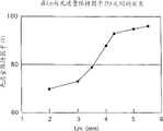
Figure 12 is presented at the hull-skin temperature of metallization sealed end and the relation between the unsealed length " Lx " used in above test.
As what see from figure, when non-tight length " Lx " when being 2.0mm, the hull-skin temperature of metallization sealed end is 950 ℃.Here, the distance of measuring on the arc lamp tube direction of principal axis between metallization sealed end and approaching metallizes the top of electrodes of sealed end is " (L0-Le)/2+Lx=4.7mm ".Therefore, the hull-skin temperature of the sealed end that wherein metallizes is no more than 950 ℃ scope is not shorter than 4.7mm corresponding to a distance of wherein measuring on the arc lamp tube direction of principal axis between metallization sealed end and approaching metallizes the top of electrodes of sealed end scope.
In addition, when non-tight length " Lx " when being 14.0mm, the hull-skin temperature of metallization sealed end is 740 ℃.Here, the distance of measuring on the arc lamp tube direction of principal axis between metallization sealed end and approaching metallizes the top of electrodes of sealed end is " (L0-Le)/2+Lx=16.7mm ".Therefore, the hull-skin temperature of the sealed end that wherein metallizes be from 740 ℃ to 950 ℃ scope corresponding to one wherein at the metallization sealed end and the distance of measuring at the arc lamp tube direction of principal axis the top of electrodes of the sealed end that approaches to metallize be scope from 4.7mm to 16.7mm.
The present invention has also described by being defined in the distance between metallization sealed end and the top of electrodes can improve the structure that cracking damages or glow color changes that luminous efficiency also stops arc lamp tube simultaneously.Yet, the temperature of metallization sealed end when essence of the present invention originally was to be defined in aforesaid steady illumination, that is, and the hull-skin temperature of metallization sealed end.Also stop the cracking damage of arc lamp tube or the purpose that glow color changes simultaneously for above improvement luminous efficiency, can not stipulate other parameters basically, for example, the non-tight length " Lx " of total length " La " and tubule parts.This is the wattage that will depend on specified lamp because of total length " La ", non-tight length " Lx " etc., the tube wall load of setting, basic structure of arc lamp tube or the like.For example, when high-pressure discharge lamp was used in certain field, in view of the life-span that prolongs lamp, tube wall load that can arc lamp tube was set to more relatively low.In this case, non-tight length " Lx " is further shortened, so that keep discharge space to be in best high temperature when illumination.
(amendment scheme)
Though the present invention is based on above-mentioned preferred embodiment description, the present invention should not be limited to above embodiment.For example, following amendment scheme is possible.
(1) though first to the 4th embodiment describes wherein king light duct member and tubule parts prepares dividually, be assembled together then to form arc lamp tube, the present invention should not be limited to this point.King light duct member and tubule parts can be created integral to.
(2) though first to the 4th embodiment describe tubule parts 4 and 5 wherein be by use the sealing of metallization Sealing Technology and molybdenum capillary 6 and 7 as conductor, the present invention should not be limited to this point.For example, one of tubule parts can be by using another kind of method (for example, sintering Sealing Technology) and conductor sealing.At least the luminous efficiency of lamp that adopts the metallization Sealing Technology in one of tubule parts is than the luminous efficiency height that adopts the lamp of sintering Sealing Technology in two tubule parts, because the length of these tubule parts at least by using the sealing of metallization Sealing Technology can be shortened.
Under the situation of using metallization Sealing Technology sealing tubule parts, do not use the molybdenum capillary, but electrode bar is fixed by ceramic binder (frit) by the tubule parts.
(3) though first to the 4th embodiment describes the situation that wherein the present invention is applied to metal halid lamp, the present invention can be applied to other general high-pressure discharge lamps, such as high-pressure mercury lamp.
Though the present invention is fully described by means of example with reference to accompanying drawing, should be pointed out that various changes and revise will be conspicuous for those skilled in the art.So unless such change and correction are to deviate from scope of the present invention, they should be looked at as and be included in the scope of the present invention.