CN1286684C - Ventilation component, ventilation casing, anti-extrction component and external member for forming ventilation structure - Google Patents
Ventilation component, ventilation casing, anti-extrction component and external member for forming ventilation structure Download PDFInfo
- Publication number
- CN1286684C CN1286684C CNB031491626A CN03149162A CN1286684C CN 1286684 C CN1286684 C CN 1286684C CN B031491626 A CNB031491626 A CN B031491626A CN 03149162 A CN03149162 A CN 03149162A CN 1286684 C CN1286684 C CN 1286684C
- Authority
- CN
- China
- Prior art keywords
- ventilation
- housing
- ventilation component
- ventilation element
- breathable films
- Prior art date
- Legal status (The legal status is an assumption and is not a legal conclusion. Google has not performed a legal analysis and makes no representation as to the accuracy of the status listed.)
- Expired - Lifetime
Links
Images








Classifications
-
- H—ELECTRICITY
- H05—ELECTRIC TECHNIQUES NOT OTHERWISE PROVIDED FOR
- H05K—PRINTED CIRCUITS; CASINGS OR CONSTRUCTIONAL DETAILS OF ELECTRIC APPARATUS; MANUFACTURE OF ASSEMBLAGES OF ELECTRICAL COMPONENTS
- H05K5/00—Casings, cabinets or drawers for electric apparatus
- H05K5/02—Details
- H05K5/0213—Venting apertures; Constructional details thereof
-
- F—MECHANICAL ENGINEERING; LIGHTING; HEATING; WEAPONS; BLASTING
- F21—LIGHTING
- F21S—NON-PORTABLE LIGHTING DEVICES; SYSTEMS THEREOF; VEHICLE LIGHTING DEVICES SPECIALLY ADAPTED FOR VEHICLE EXTERIORS
- F21S45/00—Arrangements within vehicle lighting devices specially adapted for vehicle exteriors, for purposes other than emission or distribution of light
- F21S45/30—Ventilation or drainage of lighting devices
-
- A—HUMAN NECESSITIES
- A01—AGRICULTURE; FORESTRY; ANIMAL HUSBANDRY; HUNTING; TRAPPING; FISHING
- A01K—ANIMAL HUSBANDRY; AVICULTURE; APICULTURE; PISCICULTURE; FISHING; REARING OR BREEDING ANIMALS, NOT OTHERWISE PROVIDED FOR; NEW BREEDS OF ANIMALS
- A01K63/00—Receptacles for live fish, e.g. aquaria; Terraria
- A01K63/003—Aquaria; Terraria
-
- A—HUMAN NECESSITIES
- A01—AGRICULTURE; FORESTRY; ANIMAL HUSBANDRY; HUNTING; TRAPPING; FISHING
- A01K—ANIMAL HUSBANDRY; AVICULTURE; APICULTURE; PISCICULTURE; FISHING; REARING OR BREEDING ANIMALS, NOT OTHERWISE PROVIDED FOR; NEW BREEDS OF ANIMALS
- A01K63/00—Receptacles for live fish, e.g. aquaria; Terraria
- A01K63/04—Arrangements for treating water specially adapted to receptacles for live fish
- A01K63/045—Filters for aquaria
-
- A—HUMAN NECESSITIES
- A01—AGRICULTURE; FORESTRY; ANIMAL HUSBANDRY; HUNTING; TRAPPING; FISHING
- A01K—ANIMAL HUSBANDRY; AVICULTURE; APICULTURE; PISCICULTURE; FISHING; REARING OR BREEDING ANIMALS, NOT OTHERWISE PROVIDED FOR; NEW BREEDS OF ANIMALS
- A01K63/00—Receptacles for live fish, e.g. aquaria; Terraria
- A01K63/04—Arrangements for treating water specially adapted to receptacles for live fish
- A01K63/047—Liquid pumps for aquaria
-
- F—MECHANICAL ENGINEERING; LIGHTING; HEATING; WEAPONS; BLASTING
- F21—LIGHTING
- F21V—FUNCTIONAL FEATURES OR DETAILS OF LIGHTING DEVICES OR SYSTEMS THEREOF; STRUCTURAL COMBINATIONS OF LIGHTING DEVICES WITH OTHER ARTICLES, NOT OTHERWISE PROVIDED FOR
- F21V31/00—Gas-tight or water-tight arrangements
- F21V31/03—Gas-tight or water-tight arrangements with provision for venting
-
- H—ELECTRICITY
- H02—GENERATION; CONVERSION OR DISTRIBUTION OF ELECTRIC POWER
- H02K—DYNAMO-ELECTRIC MACHINES
- H02K5/00—Casings; Enclosures; Supports
- H02K5/04—Casings or enclosures characterised by the shape, form or construction thereof
- H02K5/10—Casings or enclosures characterised by the shape, form or construction thereof with arrangements for protection from ingress, e.g. water or fingers
-
- H—ELECTRICITY
- H05—ELECTRIC TECHNIQUES NOT OTHERWISE PROVIDED FOR
- H05K—PRINTED CIRCUITS; CASINGS OR CONSTRUCTIONAL DETAILS OF ELECTRIC APPARATUS; MANUFACTURE OF ASSEMBLAGES OF ELECTRICAL COMPONENTS
- H05K5/00—Casings, cabinets or drawers for electric apparatus
- H05K5/02—Details
- H05K5/0213—Venting apertures; Constructional details thereof
- H05K5/0216—Venting plugs comprising semi-permeable membranes
-
- H—ELECTRICITY
- H02—GENERATION; CONVERSION OR DISTRIBUTION OF ELECTRIC POWER
- H02K—DYNAMO-ELECTRIC MACHINES
- H02K2205/00—Specific aspects not provided for in the other groups of this subclass relating to casings, enclosures, supports
- H02K2205/09—Machines characterised by drain passages or by venting, breathing or pressure compensating means
Landscapes
- Life Sciences & Earth Sciences (AREA)
- Engineering & Computer Science (AREA)
- Environmental Sciences (AREA)
- General Engineering & Computer Science (AREA)
- Marine Sciences & Fisheries (AREA)
- Animal Husbandry (AREA)
- Biodiversity & Conservation Biology (AREA)
- Microelectronics & Electronic Packaging (AREA)
- Power Engineering (AREA)
- Arrangement Of Elements, Cooling, Sealing, Or The Like Of Lighting Devices (AREA)
- Non-Portable Lighting Devices Or Systems Thereof (AREA)
- Casings For Electric Apparatus (AREA)
- Self-Closing Valves And Venting Or Aerating Valves (AREA)
- Cooling Or The Like Of Electrical Apparatus (AREA)
- Connection Of Plates (AREA)
- Securing Globes, Refractors, Reflectors Or The Like (AREA)
- Hooks, Suction Cups, And Attachment By Adhesive Means (AREA)
Abstract
Description
技术领域technical field
本发明涉及一种固定在汽车电气部件等的壳体上的通气元件,以及其上固定通气元件的壳体。The present invention relates to a ventilating element fixed on a housing of an automobile electrical component, etc., and a housing on which the ventilating element is fixed.
背景技术Background technique
通气元件被安装到诸如ECU(电子控制装置)、灯、电动机、各种传感器、压力开关和致动器这样的汽车电气部件;移动电话、照相机、电动剃须刀、电动牙刷及室外用灯的各种壳体上。Ventilation elements are mounted to automotive electrical components such as ECU (Electronic Control Unit), lamps, motors, various sensors, pressure switches, and actuators; mobile phones, cameras, electric shavers, electric toothbrushes, and outdoor lamps on various shells.
每种通气元件都防止水或灰尘侵入壳体的内部,同时根据通气元件所安装于其上的壳体的种类而起到各种作用。这些作用包括声音的传播、壳体内所产生气体的排出以及缓解由温度变化而引起的壳体内的压力变化。Each of the ventilation members prevents the intrusion of water or dust into the inside of the housing while performing various functions depending on the kind of the housing on which the ventilation member is mounted. These actions include the transmission of sound, the expulsion of gases generated within the enclosure, and the mitigation of pressure changes within the enclosure caused by temperature changes.
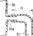
图17A和17B显示出相关技术的通气元件的一个实例。图17A和17B的每个图中所显示出的通气元件51用于暴露于诸如雨水、泥浆水或油这样的污染物的设备壳体上,例如,用于机动车电气部件的设备壳体上。通气元件51具有一L形或U形(未示出)管状体。通气元件51可具有一内部具有迷宫52的结构。通气元件51的一端与设置在壳体50内的颈部(neckportion)50a外部配合,从而通气元件51被固定到该壳体上。17A and 17B show an example of a related art ventilation element. The
图18A和18B显示出相关技术的通气元件的另一个实例。在图18A和18B中所示的通气元件60中,一近似圆筒体62配装到盖部件61的内侧,以便在盖部件61的内周面和近似圆筒体62的外周面之间以及在盖部件61的底表面和近似圆筒体62的底部之间形成通风路径。当在近似圆筒体62底部的开口用过滤器63覆盖时,通气元件60也可表现出更高的防水特性和更高的防尘特性(这在日本专利公开文献No.JP-A-2001-143524中公开)。在近似圆筒体62的顶部上的开口62a与壳体50的颈部50a外部配合,从而通气元件60固定到壳体上。18A and 18B show another example of the related art ventilation element. In the
图19显示出相关技术的通气元件的另一个实例。在图19所示的通气元件70中,一个圆锥形插入部分71a形成于一圆盘状弹性元件71的一端部,同时一防溅罩(splash guard cover)71b形成于该圆盘形弹性元件71的另一端部,并且透气薄膜72通过熔焊被固定在通风流动路径上,其中该通风流动路径在所述一端部和另一端部的外周面之间穿过。另外,与插入部分71a配合来固定地保持壳体7的密封/固定部分71c形成于弹性元件71的外周上(这已在日本专利公开文献JP-A-H10-85536号中公开)。插入部分71a被压入该壳体的开口部分从而通气元件70固定到壳体上。Fig. 19 shows another example of a related art ventilation element. In the ventilation element 70 shown in FIG. 19, a conical insertion portion 71a is formed at an end portion of a disc-shaped elastic member 71, and a splash guard cover (splash guard cover) 71b is formed at the disc-shaped elastic member 71. The other end portion of the air-permeable film 72 is fixed on the ventilation flow path passing between the outer peripheral surfaces of the one end portion and the other end portion by welding. In addition, a sealing/fixing portion 71c that cooperates with the insertion portion 71a to fixedly hold the
然而,这些通气元件具有下列问题。However, these ventilation elements have the following problems.
图17A、17B、18A和18B中所示的每个通气元件51和60仅仅通过与壳体50的颈部50a的外部配合而固定到壳体50上。因此,通气元件有可能从该壳体上拔出。Each of the
另一方面,在图19所示的通气元件70中,抵靠壳体7的表面由弹性体制成。因此,当油侵入通气元件70与壳体7抵靠的表面的一部分内时,通气元件70很容易与壳体分开。因此不能说该通气元件70适用于油很容易附着在通气元件上的环境中所使用的壳体上。On the other hand, in the ventilation element 70 shown in FIG. 19, the surface abutting against the
发明内容Contents of the invention
根据本发明,提供了一种通气元件,具有:一个透气薄膜和一个支座,其中透气薄膜以该透气薄膜固定到开口部分上状态传送流过壳体开口部分的气体;而支座包括一用来支撑透气薄膜的支撑部分以及插入该壳体的开口部分的插入部分,其中插入部分在其插入起始一侧的端部处具有一锁定部分,该锁定部分具有一锥形前端,同时插入部分至少在其插入起始侧沿圆周方向分成多个部分。According to the present invention, there is provided a ventilation element having: a gas-permeable film and a support, wherein the gas-permeable film transmits gas flowing through the opening portion of the housing with the gas-permeable film fixed to the opening portion; and the support includes a To support the supporting part of the air-permeable film and the insertion part inserted into the opening part of the housing, wherein the insertion part has a locking part at the end of the insertion start side thereof, and the locking part has a tapered front end, while the insertion part At least on its insertion start side, it is divided into a plurality of parts in the circumferential direction.
本发明的通气壳体的特征在于通气元件固定到壳体的开口部分上。The ventilation housing of the present invention is characterized in that the ventilation member is fixed to the opening portion of the housing.
根据本发明,提供了一种与本发明通气元件一起使用的用于通气元件的防拔出元件,其特征在于:该防拔出元件包括一插入到插入部分内的柱状部分,而该插入部分插入开口部分中,以便穿过该开口部分,从而插入部分从其内侧展开,并且在该柱状部分上形成一通气孔,当防拔出元件被插入该插入部分时,该通气孔与通气元件的通孔相连通。According to the present invention, there is provided an anti-extraction element for a ventilating element for use with the ventilating element of the present invention, characterized in that the anti-extraction element comprises a cylindrical portion inserted into the insertion portion, and the insertion portion is inserted into the opening portion so as to pass through the opening portion, so that the insertion portion expands from its inner side, and a vent hole is formed on the columnar portion, and the vent hole communicates with the ventilation element when the pull-out preventing member is inserted into the insertion portion. The holes are connected.
根据本发明,此处提供了一种用于形成通风结构的套件,该通风结构包括本发明的通气元件以及用于本发明通气元件的防拔出元件。According to the invention, there is provided a kit for forming a ventilation structure comprising a ventilation element of the invention and an anti-extraction element for the ventilation element of the invention.
附图说明Description of drawings
图1是示出根据本发明的通气元件的一个实施例的分解视图;Figure 1 is an exploded view showing one embodiment of a ventilation element according to the present invention;
图2A是图1所示通气元件的底视图,而图2B是沿图2A中的A-A’线截取的剖面图;Fig. 2A is a bottom view of the ventilation element shown in Fig. 1, and Fig. 2B is a sectional view taken along line A-A' in Fig. 2A;
图3是示出根据本发明的通气元件的另一实施例的剖面图;Figure 3 is a sectional view showing another embodiment of the ventilation element according to the present invention;
图4A和4B是示出通气元件的一个支腿部分2h插入其他通气元件的通孔3中的状态的视图;4A and 4B are views showing a state where one
图5是示出根据本发明的通气元件的另一实施例的剖面图;5 is a cross-sectional view showing another embodiment of the ventilation element according to the present invention;
图6A是示出根据本发明通气元件的另一实施例的分解视图;而图6B是图6A所示的通气元件的剖面图;Figure 6A is an exploded view showing another embodiment of the ventilation element according to the present invention; and Figure 6B is a cross-sectional view of the ventilation element shown in Figure 6A;
图7是示出根据本发明通气元件的另一实施例的剖面图;Figure 7 is a sectional view showing another embodiment of the ventilation element according to the present invention;
图8A是图7所示的通气元件的正视图,而图8B是从图8A所示的通气元件的底视图中省略掉密封部分的视图;FIG. 8A is a front view of the ventilation element shown in FIG. 7, and FIG. 8B is a view omitting the sealing portion from the bottom view of the ventilation element shown in FIG. 8A;
图9A是本发明通气元件的另一实施例的正视图,而图9B是从图9A所示的通气元件的底视图中省略掉密封部分的视图;Fig. 9A is a front view of another embodiment of the ventilation element of the present invention, and Fig. 9B is a view omitting the sealing part from the bottom view of the ventilation element shown in Fig. 9A;
图10是示出防拔出元件安装在图9所示通气元件上的状态的正视图;Fig. 10 is a front view showing a state in which the pull-out preventing member is installed on the ventilation member shown in Fig. 9;
图11是示出图10所示的防拔出元件的剖面图;Fig. 11 is a sectional view showing the pull-out prevention element shown in Fig. 10;
图12A是根据本发明通气元件固定于其上的连接器的透视图;而图12B是沿图12A中的B-B’线截取的剖面图;Figure 12A is a perspective view of a connector on which the ventilation element is fixed according to the present invention; and Figure 12B is a sectional view taken along the line B-B' in Figure 12A;
图13A是根据本发明的通气元件安装于其上的汽车灯的透视图,而图13B是沿图13A中的C-C’线截取的剖面图;13A is a perspective view of an automobile lamp on which a ventilation element according to the present invention is mounted, and FIG. 13B is a sectional view taken along line C-C' in FIG. 13A;
图14是本发明的通气元件安装于其上的电动牙刷的局部剖面图;14 is a partial sectional view of an electric toothbrush on which the ventilation element of the present invention is installed;
图15A是本发明的通气元件已安装于其上的ECU的透视图,而图15B是ECU盖的顶盖的后视图;FIG. 15A is a perspective view of an ECU on which a ventilation member of the present invention has been mounted, and FIG. 15B is a rear view of a top cover of an ECU cover;
图16A是对比例3的通气元件的正视图,图16B是从图16A所示的通气元件的底视图中省略密封部分的视图;16A is a front view of the ventilation element of Comparative Example 3, and FIG. 16B is a view in which a sealing portion is omitted from the bottom view of the ventilation element shown in FIG. 16A;
图17A和17B是示出相关技术的通气元件的一个实例的剖面图;17A and 17B are cross-sectional views showing an example of a related art ventilation element;
图18A是解释相关技术通气元件的另一实例的分解图,而图18B是图18A所示的通气元件的剖面图;以及FIG. 18A is an exploded view explaining another example of the related art ventilation element, and FIG. 18B is a sectional view of the ventilation element shown in FIG. 18A; and
图19是用来解释相关技术的通气元件另一实例的剖面图。Fig. 19 is a cross-sectional view of another example of the ventilation member for explaining the related art.
具体实施方式Detailed ways
下面将参照附图来描述本发明的优选实施例。Preferred embodiments of the present invention will be described below with reference to the accompanying drawings.
(第一实施例)(first embodiment)
现在将参照图1至6B来对本发明的通气元件的一个实施例进行描述。One embodiment of the ventilation element of the present invention will now be described with reference to Figures 1 to 6B.
图1、2A和2B所示的通气元件1包括一支座2和一透气薄膜4。支座2包括一用于支撑透气薄膜4的支撑部分2a以及一形成于支撑部分2a一侧的插入部分2b。在支座2的中央部分形成贯穿支撑部分2a和插入部分2b的通孔3。透气薄膜4被固定地连接到支撑部分2a上以便覆盖通孔3。The
插入部分2b为柱状,其直径与壳体7开口部分8的直径基本上相同。至少插入部分2b的插入起始侧沿周边分成多个部分。插入部分2b包括至少多个设置于插入起始侧的支腿部分2h,以便在相邻支腿部分2h之间形成狭缝2i。每个支腿部分2h包括一锁定部分2c,锁定部分的外周表面在插入起始侧的一端是锥形的。The
当通气元件1固定到壳体7的开口部分8上时,通过将插入部分2b插入该开口部分而将锁定部分2c按压在开口部分8上,使得插入部分2b的分开的各部分(支腿部分2h)向内弯曲。从而,通气元件1相对于壳体7的插入压力减小。当锁定部分2c通过开口部分8并且不再受该压力的作用时,锁定部分2c被锁定在壳体的内表面上。于是,通气元件1被固定在壳体7上。一旦通气元件1被固定在壳体7上,除非用足以毁坏该通气元件1和/或壳体7那么大的力来拔通气元件1,否则通气元件1不会被从壳体7的外侧卸掉。于是,通气元件1与壳体7分开的可能性被降低了。When the
在图1、2A和2B所示的实施例中,插入部分2b的插入起始侧沿周向被分成三份。分开部分的数目并不限于此,而可以是两个或四个或更多。此外,在图1、2A和2B所示的实施例中,插入部分2b的纵向部分被分成多个部分。本发明并不限于此,而是整个的插入部分2b可被纵向地分成多个部分。尽管在该实施例中所有的支腿部分2h都包括锁定部分2c,但是锁定部分可以设置在至少一个,优选两个或更多个支腿部分2h上。优选地,锁定部分2c形成为至少离开插入部分2c在插入起始侧的末端0.1mm。如果在插入起始侧的端部形成一平坦部分,则插入部分2b可容易地插入壳体的开口部分8内。In the embodiment shown in FIGS. 1, 2A and 2B, the insertion start side of the
支撑部分2a的形状没有特别地限定,但是可以是如图1、2A和2B所示的,具有比插入部分2b的直径大的直径的圆盘。支撑部分2a可具有比形成于壳体7上的开口部分8的直径大的直径,以便设置成覆盖开口部分8。The shape of the
此外,支撑部分2a与透气薄膜4抵靠的表面形成为如图2B所示的曲面。以这种方式,设置了这样一种通气元件,其曲面在支撑部分2a的表面处具有高度低于中央部分的周边部分,这样适当地提高了作为用在容易受水影响环境中的壳体的通气元件的一个特性的排水特性。顺便提一句,例如,支撑部分2a的形状可以被形成为圆锥形,而不是如上所述的支撑部分2a的曲面。在这种情况下,透气薄膜4牢固地安装在圆锥形的斜面上,从而排水特性得到了提高。In addition, the surface of the supporting
通孔3的尺寸可考虑通气元件1安装于其上的壳体的种类以及透气薄膜4的渗透性来适当地确定。通孔3的面积(垂直于气体渗透方向的平面上的面积)可被设定为0.001-100cm2。The size of the through
此外,如图2B所示,在被透气薄膜4覆盖住的表面内可设置多个通孔3。当以如此方式在被透气薄膜4覆盖住的表面内形成多个通孔3时,透气薄膜4的中心也被支撑部分2a支撑。因此,有可能防止透气薄膜4受到外力的破坏。In addition, as shown in FIG. 2B , a plurality of through
如图3所示,可以在被透气薄膜4覆盖住的表面上形成单个通孔3。如果通孔3的直径较大,则透气性提高了。另外,如果该直径足够大,并且在通孔3的纵向上保持不变,则防止了在围绕该通孔的支撑元件2侧壁上凝结将阻碍空气流通的水汽。然而,如果通孔较大,恐怕在多个通气元件在一个包装中包裹并运输或传送时,通气元件的支腿部分2h会破坏透气薄膜4。As shown in FIG. 3 , a single through-
图4A和4B示出通气元件X的支腿部分2h被插入其他通气元件Y的通孔中。图4A和4B是从空气穿过的方向上看去的平面图。分别地,通气元件X自支撑部分2a一侧观察,通气元件Y自插入部分2b一侧观察。在图中,通气元件X的透气薄膜被省略了。在从空气穿过的方向观察的平面图中,支座(相当于图4A和4B中的支撑部分2a)呈现为环形。4A and 4B show that the
如图4A所示,如果尺寸A小于尺寸B,通气元件X的支腿部分2h可深深插入通气元件Y的通孔3中,从而通气元件Y的透气薄膜被破坏了。尺寸A被定义为环宽度的最小值(最小环宽度),尺寸B被定义为两个相邻支腿部分之间的最近距离,在插入部分2b的插入起始侧端部,这两个支腿之间的最近距离比其它任何一对相邻支腿部分之间的最近距离大(支腿部分之间的最大距离)。As shown in FIG. 4A, if the dimension A is smaller than the dimension B, the
如从空气穿过方向观察的图4A的平面图所示,如果支撑部分2a和通孔3的外部形状是正圆形(true circle)并且这些圆为同心的,则在任何部分的环宽度为常数。因此,该值被确定为尺寸A。另外,如图4A所示,支腿部分2h具有相同的形状并被以恒定的间隔设置,则在插入部分2b的插入起始侧端部,支腿部分2h中的任何两个相邻支腿部分之间的最近距离相同,因此,该值被确定为B。As shown in the plan view of FIG. 4A viewed from the air passing direction, if the outer shapes of the
如图4B所示,当尺寸A被设定成比尺寸B大时,即使通气元件X的支腿部分2h深深地进入通气元件Y的通孔3中,通气元件X的支撑部分2a与通气元件Y的支腿部分2h相邻接,从而防止了通气元件X的支腿部分2h插入通气元件Y的通孔3中。因此,防止了支腿部分2h对其他通气元件的透气薄膜4的损坏,并防止了支腿部分2h与其他通气元件的支腿部分交错在一起。通气元件的处理很容易完成。As shown in FIG. 4B, when the dimension A is set to be larger than the dimension B, even if the
优选使用易于模制的热塑性树脂作为支座2的材料,而没有任何特殊的限制。要被使用的这种材料的实例包括弹性体以外的热塑性树脂,如聚对苯二甲酸二丁烯酯(PBT)、聚对苯二甲酸乙二醇酯(PET)、聚亚苯基硫醚(PPS)、聚砜(PS)、聚丙烯(PP)、聚乙烯(PE)、ABS树脂或这些热塑性树脂的合成材料。除了热塑性树脂以外,也可使用如下的合成材料,其中诸如玻璃纤维或碳纤维这样的加强材料或金属与热塑性树脂合成以提高耐热性、耐湿性、尺寸稳定性和刚性。另外,通气元件1通过压配合而固定到壳体上。因此优选使用抗冲击性优良、弯曲强度高的材料,如PBT、PPS或PS。特别地,当使用PBT时,优选在该材料中包含重量上5至40%的玻璃纤维。另外,可以在用上述材料形成的支座2的表面上进行处理以获得所需的特性,如脱模性(mold release)、粘着性改进、电绝缘、半导电性、电导率等等。An easily moldable thermoplastic resin is preferably used as the material of the
形成支座2的方法没有特别的限制。例如,支座2可以通过注模、压模成型或切削来形成。The method of forming the
如果能确保足够的渗透性,则透气薄膜4的材料、结构及形成没有特别的限制。然而,优选的是从含氟树脂多孔材料和聚烯烃多孔材料中选择至少一种。含氟树脂的实例包括:聚四氟乙烯(PTFE)、聚氯三氟乙烯、四氟乙烯-六氟丙烯共聚物、四氟乙烯-全氟烃基乙烯醚共聚物、以及四氟乙烯-乙烯共聚物。聚烯烃单体的实例包括乙烯、丙烯、4-甲基戊烯-1、以及1-丁烯。通过这些单体的简单聚合或共聚合而得到的聚烯烃也可被使用。另外,两种或多种这样的聚烯烃可被混合或层压成层。在这些材料中,PTFE多孔材料是特别优选,因为即使在小面积内它也能保持渗透性,并且它具有很高的防止水或灰尘侵入壳体内部的功能。The material, structure and formation of the air
如图1至图3所示,加强材料5可层压到透气薄膜4上。当加强材料5以这种方式层叠到透气薄膜4的一侧时,加强材料5也可被层叠到与图1至3所示透气薄膜4的加强材料5层叠于其上的表面相反的表面上。加强材料5的材料、结构及形成没有特别的限制。然而,优选使用具有比透气薄膜4大的孔径尺寸以及优良透气性的材料,如机织织物、非织布、网眼、网状物、海绵、泡沫、金属多孔材料或金属网。当需要耐热性时,优选使用由聚酯、聚酰胺、芳族聚酰胺树脂、聚酰亚胺、氟树脂、超高分子量聚乙烯或金属制得的加强材料。顺便说一句,尽管在图1至图3所示的实施例中加强材料5被层叠到透气薄膜4的一侧,加强材料5也可被层叠到透气薄膜4的两侧。透气薄膜4可被层叠到加强材料5的两侧面上。The
至于将加强材料5层叠到透气薄膜4上的方法,它们可以被简单地彼此叠放,或接合到一起。例如,可以用粘结剂层叠、热层叠(thermallamination)、加热沉积(heating deposition)、超声波沉积(ultrasonicdeposition)、或用粘结剂粘结的方法完成连接。例如,当通过热层叠对透气薄膜4和加强材料5进行层叠时,一部分加强材料5可被加热并被熔化以被粘结到透气薄膜4上。于是,透气薄膜4不用粘结剂就被粘结到加强材料5上,避免了不必要的重量增加以及透气性的下降。可选地,透气薄膜4和加强材料5可用如热熔粉末的熔焊剂粘结在一起。As for the method of laminating the
由透气薄膜4和加强材料5层叠而成的叠片的透气性(Gurley值)优选在0.1-300秒/100cm3范围内,更为优选的是在1.0-100秒/100cm3范围内。抗水压力优选不小于1.0kPa。The air permeability (Gurley value) of the laminate formed by laminating the
根据壳体的用途,可以对透气薄膜4进行防液体处理,如防水处理或防油处理。可以通过在透气薄膜4上涂覆表面张力小的物质、干燥该物质然后固化该物质来完成防液体处理。防液体剂没有特别的限制,只要表面张力比透气薄膜小的涂层都可形成为防液体剂。然而,优选使用具有全氟代烷基族的聚合物。要使用的这种聚合物的例子包括Fluorad(由Sumitomo3M有限公司生产)、Scotchguard(由Sumitomo 3M有限公司生产)、Texguard(由大金工业有限公司生产)、Unidyne(由大金工业有限公司生产)以及Asahi guard(由Asahi玻璃有限公司生产)(所有这些都是商品名称)。防液体剂可以通过浸渍或喷射来施加。According to the application of the shell, the air-
至于将透气薄膜4支撑在支撑部分2a上的方法,由于几乎不发生剥离或漂移,因此加热沉积、超声波沉积或利用粘结剂来粘结中的任一种方法都是适合的。从操作方便的角度来看,加热沉积或超声波沉积是优选的。当加强材料5层叠到透气薄膜4上时,只要加强材料5可被固定地安装到支座2上,可以使用任何支撑方法而没有特别地限制。顺便说一句,当需要高防液体性能时,优选地,加强材料5牢固附着到支撑部分2a上,而防液体性能较高的表面面向壳体的外侧。As for the method of supporting the air-
作为将透气薄膜4支撑到支撑部分2a上的另一种方法,当注模支座2时,透气薄膜4可被设置在用于形成支座2的模具内。在这种情况下,透气薄膜4与支座2结合为一整体。As another method of supporting the air-
透气薄膜4的厚度或者由透气薄膜4和加强材料5层叠而成的叠层元件的厚度优选被设定为在1μm至5mm的范围内。如果该膜比1μm薄,则该膜容易破损,而如果该膜比5mm厚,则很难将该膜支撑在支撑部分上。The thickness of the air-
另外,如图5所示,当密封部分2d设置在支撑部分2a的面向壳体的表面上时,可以提高壳体7与通气元件1之间的附着力或气密性。特别是当弹性体之外的热塑性树脂用作支撑部分2a时,优选形成密封部分2d以提高密封性能。In addition, as shown in FIG. 5, when the sealing
用于密封部分的优选材料的例子包括弹性体,如丁腈橡胶(NBR)、乙烯-丙烯橡胶(EPM或EPDM)、硅橡胶、含氟橡胶(fluoric rubber)、丙烯酸橡胶、氢化丁腈橡胶(HNBR)、泡沫材料或用粘结层形成的材料。Examples of preferred materials for the sealing portion include elastomers such as nitrile rubber (NBR), ethylene-propylene rubber (EPM or EPDM), silicone rubber, fluoric rubber, acrylic rubber, hydrogenated nitrile rubber ( HNBR), foam or material formed with an adhesive layer.
例如,密封部分2d可通过将上述材料的O形圈与插入部分2b外部配合而设置,或者通过双色模制(dichromatic molding)而在支撑部分2a的一侧上形成。另外,具有粘结层的制成材料可粘结在支撑部分2a的与壳体7相对的表面上。For example, the sealing
另外,如图6A和6B所示,当支座2具有一个从透气薄膜4上方覆盖透气薄膜4至少一部分的保护部分2e时,则有可能降低透气薄膜4被外力破坏或者通气被积累在透气薄膜表面上的沙子或泥土堵塞的可能性。In addition, as shown in FIGS. 6A and 6B, when the
保护部分2e的形状并没有特殊的限制,只要该形状不会破坏通气元件1的渗透性。然而,优选的是多个开口部分2f形成在当沿气体渗透方向观察时看不见它们的位置,例如,形成于如图6A和6B所示实施例中的保护部分2e的侧面。顺便说一句,只要开口部分2f不会损坏保护透气薄膜4的效果,该开口部分2f也可形成于保护部分2e的上部表面2g上。另外,从保持保护部分2e的强度并有效地防止物质进入的角度来看,优选的是开口部分2f形成为分开的小孔。The shape of the
作为保护部分2e的材料,可以使用与支座2其它部分材料相似的材料。将保护部分2e与支座2的其它部分成为一体的方法没有特别的限制。这种整合可以通过加热沉积、超声波沉积、振动沉积、使用粘结剂粘结、装配或螺纹联接的方法来达到。特别地,由于其低成本和容易,加热沉积或超声波沉积是优选的。As the material of the
(第二实施例)(second embodiment)
在该实施例中,本发明的另一通气元件由图7、8A和8B来描述。除非给出特殊的解释,该实施例与前面的实施例相似地构成,相同的元件用相同的附图标记标示,从而省略其解释。In this embodiment, another ventilation element of the present invention is depicted by Figures 7, 8A and 8B. Unless a special explanation is given, this embodiment is constructed similarly to the previous embodiment, and the same elements are denoted by the same reference numerals, thereby omitting explanation thereof.
尽管图1、2A和2B所示的通气元件设置有插入部分2b,该部分沿其圆周方向被分成三部分,并且这三个支腿部分2h的每一个都包括位于插入起始侧端部的锁定部分(见图2B),这个实施例的通气元件21具有沿其圆周方向被分成六个部分的插入部分2b。在这六个支腿部分2h中,三个支腿部分2h包含锁定部分2c。包含锁定部分2c的支腿部分2h与不包含锁定部分2c的支腿部分2h在圆周方向上交替设置。Although the ventilation element shown in FIGS. 1, 2A and 2B is provided with an
如图1、2A和2B的通气元件所示,在每个支腿部分2h都包含有锁定部分2c的情况下,为了减小插入部分2b进入开口部分8的插入压力,应当将支腿部分2h的宽度做得较小(即,狭缝2i变得更宽),从而支腿部分2h可被容易地向内弯曲,或者应当使锁定部分2c与开口部分8的滑动接触面积更小(见图1)。然而,如果支腿部分2h的宽度变小,由于插入部分2b和开口部分8之间的接触面积减小,插入部分2b会被轻易地在开口部分8内转动。因此稳定性降低了。1, 2A and 2B ventilation elements, in the case where each
在本实施例的通气元件21中,由于插入部分2b沿圆周方向被分成更多部分,并包括不具有锁定部分2c的支腿部分2h,支腿部分2h可被轻易地向内弯曲,并且锁定部分2c和开口部分8之间的滑动接触面积减小,从而插入压力减小。另外,保持了插入部分2b与开口部分8的接触面积,从而防止了插入后位置的移动,并由此提高了稳定性。In the
在该实施例中,如图8A所示,保护部分2e的凸出部分2i配装到形成于支撑部分2a的与壳体7相对的表面上的凹槽2k中,从而保护部分2e和支撑部分2a成为一体。由于保护部分2e可与支撑部分2a相分离,因此透气薄膜4可由新的透气薄膜4更换。In this embodiment, as shown in FIG. 8A, the protruding
(第三实施例)(third embodiment)
在该实施例中,本发明的其他通气元件由图9A至11来描述。除非给出特殊解释,该实施例用与前面的实施例相似地构成,相同的元件用相同的附图标记标示,从而省略对其解释。In this embodiment, other ventilation elements of the present invention are described by FIGS. 9A to 11 . Unless a special explanation is given, this embodiment is constructed similarly to the previous embodiment, and the same elements are denoted by the same reference numerals, so that explanations thereof are omitted.
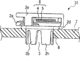
在第一和第二实施例所描述的通气元件中,两个或更多的支腿部分2h包括锥形锁定部分2c(见图2B和8B),在这个实施例中通气元件31的支腿部分2h都不包含锁定部分。插入部分2b的外径几乎等于开口部分8的直径,从而通过将插入部分2b压配合进开口部分8中,而将通气元件31固定到壳体7上。In the ventilation elements described in the first and second embodiments, two or
如图10所示,优选的是防拔出元件9设置在插入部分2b在其插入起始侧处的内部,其向壳体7内突出从而插入部分2b的插入起始侧从其内侧展开。通过用于形成包括通气元件31和防拔出元件9在内的透气结构的套件,通气元件31可被更可靠地安装到壳体7上。As shown in FIG. 10 , it is preferable that the
如图10和11所示,防拔出元件9包括插入已经插入到开口部分8中的插入部分8的柱状部分9a,以便穿过开口部分8,从而插入部分2b从其内部展开。在柱状部分9a上形成一个通气孔9b,当防拔出元件9插入到插入部分2a中时,该通气孔与通气元件的通孔3连通。从柱状部分9a的插入起始侧到插入终止侧柱状部分9a的外径变大。防拔出元件9还包括一法兰部分9c,该法兰部分9c设置于柱状部分9a的插入终止侧上,并具有比壳体7开口部分8的直径大的外径,从而防止防拔出元件9被过度地插入插入部分2b中。As shown in FIGS. 10 and 11 , the pull-out preventing
如图10和11所示,防拔出元件9还包括一折回部分9d,该部分由法兰部分9c处形成,以便围绕柱状部分9a。如果折回部分9d形成为使得支腿部分2h配合在折回部分9d和柱状部分9a之间,则防拔出元件9可以更可靠地安装在通气元件31上。此外,如果折回部分9d形成为使得折回部分9d的端面9e与相对于壳体7中的与支撑部分2a相对的表面的后表面7a在柱状元件9a插入到插入部分2b中的状态下抵靠,则通气元件31可被固定到壳体7上,从而插入部分2b不会在开口部分8中滑动。由于防拔出元件9可根据需要被取出,通气元件可被替换。用来配合的装配槽和装配凸起或者用来螺纹连接的外螺纹和内螺纹等等可形成在插入部分2b的内侧面上或者柱状部分9a外侧面上。As shown in FIGS. 10 and 11, the pull-out preventing
用于防拔出元件9的材料没有特别地限制。可以使用与支座材料相似的材料。可以使用具有象橡胶一样的弹性材料,如热塑性弹性体。The material used for the pull-out preventing
接着,图12A、12B、13A、13B、14、15A和15B分别示出本发明的通气元件安装于其上的通气壳体的实例。图1所示的通气元件1被安装在图12A和12B所示的连接器上。图6A和6B所示的通气元件1被安装在图13A和13B所示的汽车车灯上。图5所示的通气元件1被安装到图14所示的电动牙刷上。图1所示的通气元件1被安装到图15A和15B所示的ECU上。然而,本发明的通气元件安装于其上的壳体并不限于这些壳体。另外,要被安装到壳体上的根据本发明的通气元件的数目没有特别的限制。多个通气元件可安装到一个壳体的不同侧面或者一个壳体一个相同侧面上。Next, FIGS. 12A , 12B, 13A, 13B, 14 , 15A, and 15B each show an example of a ventilation housing on which a ventilation member of the present invention is mounted. The
(实例)(example)
尽管下面将通过实例来更详细地描述本发明,本发明并不局限于下述这些实例。Although the present invention will be described in more detail below by way of examples, the present invention is not limited to these examples described below.
(实例1)(Example 1)
对于实例1,图6A和6B所示的通气元件如下制造。For Example 1, the ventilation element shown in Figures 6A and 6B was fabricated as follows.
首先,具有图6A和6B所示结构的支座2通过注模由PBT(由Teijin有限公司生产的CG7640,熔点225℃)制得。所获得的支座2的支撑部分2a为2.5mm厚,外径为16mm,所获得的支座2的插入部分2b(未形成锁定部分2c的部分)的外径为5.5mm,而设置在插入部分2b中的通孔3的内径为3.5mm。保护层2e厚度为3.5mm,外径为16mm。First, the
下一步,准备厚度为0.085mm、外径为20mm的PTFE多孔材料(由Nitto Denko公司生产的Microtex NTF1131,熔点为327℃)作为透气薄膜4,准备厚度为0.2mm的聚酯基的非织物(由Toray Industries公司生产的Axtar,熔点230℃)作为加强材料5。透气薄膜4和加强材料5通过在260℃温度、5.0×10⁵帕压力下进行10秒钟的热沉积而接触粘合。于是,得到了叠层6。Next step, prepare the porous PTFE material (Microtex NTF1131 produced by Nitto Denko Company, melting point is 327 ℃) that thickness is 0.085mm, external diameter is 20mm as air-
接着,叠层6冲压成8mm外径。叠层6的加强材料5与支撑部分2a接触以便覆盖设置于支撑部分2a中的通孔3,并通过在260℃温度、5.0×10⁵帕的压力下进行30秒的热沉积而接触粘合到支撑部分2a上。接着,通过热沉积,保护部分2e和支撑部分2a固定地彼此附着。最后,作为密封部分2d的由EPDM制得的O形圈外部配合到插入部分2b上。于是,得到了通气元件A。Next, the
在另一方面,通气元件A将固定于其上的壳体通过注模由PBT(由Teijin有限公司生产的CG7640,熔点225℃)制得。所获得的壳体7的外壁厚度为2mm,开口部分8的内径为6.5mm。通气元件A用手压配合到壳体7的开口部分8中。于是得到了通气壳体A。On the other hand, the case to which the ventilation member A was to be fixed was made of PBT (CG7640 produced by Teijin Co., Ltd., melting point 225° C.) by injection molding. The outer wall thickness of the obtained
(实例2)(Example 2)
对于例2,图6A和6B所示的通气元件如下制造。For Example 2, the vent element shown in Figures 6A and 6B was fabricated as follows.
首先,具有图6A和6B所示结构的支座2通过注模由PP(由Sumitomo化学有限公司生产的AW564,熔点165℃)制得。所获得的支座2的支撑部分2a为2.5mm厚,外径为16mm,所获得的支座的插入部分2b(未形成锁定部分2c处)的外径为5.5mm,设置在插入部分2b中的通孔3的内径为3.5mm。保护部分2e厚度为3.5mm,外径为16mm。First, the
接下来,准备厚度为0.02mm、外径为20mm的PTFE多孔材料(由NittoDenko公司生产的Microtex NTF1026,熔点为327℃)作为透气薄膜4,准备厚度为0.2mm的聚酯基的非织物(由Toray Industries公司生产的Axtar,熔点230℃)作为加强材料5。透气薄膜4和加强材料5通过在260℃温度、5.0×10⁵帕压力下进行10秒钟的热沉积而接触粘合。于是,得到了叠层6。Next, prepare a PTFE porous material (Microtex NTF1026 produced by NittoDenko Company, melting point is 327° C.) with a thickness of 0.02 mm and an outer diameter of 20 mm as the
接着,叠层6冲压出8mm外径。叠层6的加强材料5与支撑部分2a接触以便覆盖设置于支撑部分2a中的通孔3,并通过在260℃温度、5.0×10⁵帕的压力下进行30秒钟的热沉积而接触粘合到支撑部分2a上。接着,通过热沉积,保护部分2e和支撑部分2a固定地彼此连接。最后,由NBR制成的O形圈作为密封部分2d外部配合到插入部分2b上。于是,得到了通气元件B。与例1相似,通气元件B用手压入配合到壳体7的开口部分8中。于是得到了通气壳体B。Next,
(实例3)(Example 3)
对于例3,图7、8A和8B所示的通气元件如下地制造。For Example 3, the ventilation element shown in Figures 7, 8A and 8B was fabricated as follows.
首先,具有图7、8A和8B所示结构的支座2通过注模由PBT(由Teijin有限公司生产的CG7640,熔点225℃)制得。所获得的支座2的支撑部分2a为3mm厚,最大外径为16.5mm,所获得的支座的插入部分2b(未形成锁定部分2c处)的外径为10mm,而设置在插入部分2b中的通孔3的内径为8.5mm,尺寸A为4.25mm,尺寸B为2.1mm。保护部分2e厚度为4.5mm,外径为17mm。First, the
接着,如实例2中所述,所获得的叠层6冲压出11mm外径,该叠层以与实例2相同的方式通过熔焊粘结到支撑部分2a上。接着,通过热沉积,保护部分2e和支撑部分2a固定地彼此连接。最后,由EPDM制成的O形圈作为密封部分2d外部配合到插入部分2b上。于是,得到了通气元件C。Next, as described in Example 2, the obtained
在另一方面,通气元件C将要固定于其上的壳体通过注模由PBT(由Teijin有限公司生产的CG7640,熔点225℃)获得。所获得壳体7的外壁厚度为2mm,开口部分8的内径为10.4mm。通气元件C用手压入配合到壳体7的开口部分8中。于是得到了通气壳体C。On the other hand, the case to which the ventilation member C is to be fixed was obtained from PBT (CG7640 produced by Teijin Co., Ltd., melting point 225° C.) by injection molding. The outer wall thickness of the obtained
(实例4)(Example 4)
对于实例4,图7、8A和8B所示的通气元件如下地制造。For Example 4, the ventilation elements shown in Figures 7, 8A and 8B were fabricated as follows.
首先,具有图7、8A和8B所示结构的支座2通过注模由PP(由Sumitomo化学有限公司生产的AW564,熔点165℃)制得。所获得的支座2的支撑部分2a为3mm厚,最大外径为16.5mm,所获得的支座的插入部分2b(未形成锁定部分2c处)的外径为10mm,设置在插入部分2b中通孔3的内径为8.5mm,尺寸A为4.25mm,尺寸B为2.1mm。保护部分2e厚度为4.5mm,外径为17mm。First, the
接着,根据如实例1所述而制得的叠层6冲压出11mm外径,该叠层用与例1相同的方法通过熔焊被粘结到支撑部分2a上。接着,通过热沉积,保护部分2e和支撑部分2a固定地彼此连接。最后,由硅橡胶制成的O形圈作为密封部分2d外部配合到插入部分2b上。于是,得到了通气元件D。Next, an outer diameter of 11 mm was punched out according to the
(实例5)(Example 5)
对于实例5,图9所示的通气元件如下地制造。For Example 5, the ventilation element shown in Figure 9 was fabricated as follows.
首先,具有图9所示结构的支座2通过注模由PBT(由Teiiin有限公司生产的CG7640,熔点225℃)制得。所获得的支座2的支撑部分2a3m厚,最大外径16.5mm,所获得的支座的插入部分2b(未形成锁定部分2c处)的外径为10mm,设置在插入部分2b中通孔3的内径为8.5mm,尺寸A为4.25mm,尺寸B为2.1mm。保护部分2e厚度为4.5mm,外径为17mm。First, the
接着,如实例1所述制得的叠层6冲压出11mm外径,该叠层用与例1相同的方法通过熔焊被粘结到支撑部分2a上。接着,通过热沉积,保护部分2e和支撑部分2a固定地彼此连接。最后,带粘结层并被冲成外径为15mm、内径为10.5mm的环形的EPDM泡沫片(由Nitto Denko公司生产的Seal-Saver,SA-612,厚度4mm)粘结在支撑部分2a的与壳体相对的表面上。于是,得到了通气元件E。Next, the
接着,具有如图11所示结构的通气元件防拔出元件9可通过注模由PBT(由Teijin有限公司生产的CG7640,熔点225℃)制得。防拔出元件9的通气孔9b的直径为4mm,柱状部分9a的最小外径为8mm,最大外径为9mm。柱状元件9a的长度(定义为从外径最小的部分至外径最大的部分的长度)为4.0mm。Next, the ventilation member pull-out preventing
通气元件E插入如实例3所述制得的壳体7的开口部分8中,接着防拔出元件9插入已插入开口部分8内的插入部分2b中。于是制得了通气壳体E。The ventilation element E was inserted into the
(对比例1)(comparative example 1)
如图17A和17B所示的通气元件F通过对以丁苯橡胶(由Asahi-Kasei公司生产的Tufdene 1000,弯曲模量4.0×10⁸N/m2)为其主要组分的材料进行模制和热风处理而制得。所获得的通气元件F内径为7.5mm,外径为11.5mm,厚度为2mm,高度H为40mm。The ventilation member F shown in FIGS. 17A and 17B is obtained by molding a material having styrene-butadiene rubber (Tufdene 1000 produced by Asahi-Kasei Co., Ltd., flexural modulus 4.0×10 8 N/m 2 ) as its main component. and hot air treatment. The obtained ventilation element F had an inner diameter of 7.5 mm, an outer diameter of 11.5 mm, a thickness of 2 mm, and a height H of 40 mm.
另一方面,如图17A和17B所示的壳体50通过注模而形成为通气元件F将要安装于其上的壳体。颈部50a形成为中空的圆柱形状,其外径比通气元件F的内径大20%。通气元件F的一端与颈部50a外部配合8mm。于是,得到了通气壳体。On the other hand, the
(对比例2)(comparative example 2)
如图18A和18B所示的盖部61和近似圆筒体62通过注模分别由PP(由Ube Industries有限公司生产的UBE Polypro J815HK,弯曲模量1.47×10⁹N/m2)和热塑性弹性体(由Mitsui化学公司生产的Milastomer 6030,弯曲模量4.41×10⁸N/m2)制得。所获得的盖部61外径为17.5mm、内径为15.5mm,所获得的近似圆筒体62的最大外径为15.5mm、顶部开口部分62a处的内径为7.5mm。The
另外,准备PTFE多孔材料(由Nitto Denko公司生产的MicrotexNTF1026,厚度为0.02μm、平均孔径大小为0.6μm、孔隙度为80%)作为通风过滤器63。接着,将通风过滤器63与制得的近似圆筒体62的底部相接触,并然后通过在150℃温度、10×104帕的压力下热沉积10秒,而接触粘合到所获得的近似圆筒体62的底部上。然后近似圆筒体62装配到上盖部61上。于是制得了通气元件G。In addition, a PTFE porous material (Microtex NTF1026 produced by Nitto Denko Co., Ltd., thickness 0.02 μm, average pore size 0.6 μm, porosity 80%) was prepared as the
另一方面,如图18B所示的壳体50通过注模而制成为通气元件G将要安装于其上的壳体。颈部50a被形成为中空的圆柱形状,其外径比顶部开口部分62a的内径大20%。通气元件G与颈部50a外部配合8mm。于是,得到了通气壳体G。On the other hand, a
(对比例3)(comparative example 3)
作为对比例3,如图16所示的通气元件如下制得。As Comparative Example 3, a ventilation element as shown in FIG. 16 was produced as follows.
如图16所示的结构通过注模由PBT(由Teijin有限公司制得的CG7640,熔点225℃)制得。所获得的支座2的支撑部分2a的厚度为3mm,最大外径为16.5mm,所获得的支座的插入部分2b(未形成锁定部分2c处)的外径为10mm,设置在插入部分2b中的通孔3内径为8.5mm,尺寸A为4.25mm,尺寸B为6.2mm。保护部分2e厚度为4.5mm,外径为17mm。The structure shown in FIG. 16 was made of PBT (CG7640 manufactured by Teijin Co., Ltd., melting point 225° C.) by injection molding. The supporting
接着,如实例1所述制得的叠层6冲压出11mm外径,并且该叠层用与例1相同的方法通过熔焊被粘合到支撑部分2a上。接下来,保护部分2e和支撑部分2a通过热沉积固定地彼此连接。最后,冲成15mm外径、10.5mm内径的环形的具有粘结层的EPDM泡沫片(由Nitto Denko公司生产的Seal-Saver,SA-612,厚度为4mm)粘结在支撑部分2a的与壳体相对的表面上。于是得到了通气元件H。通气元件H用手压配合到如例3所述制得的壳体7的开口部分8中。于是制得了通气壳体H。Next, the
在这样得到的通气壳体上用下述方法测量拔出力。结果,通气元件A到E(实例1到5)和通气元件H(对比例3)不能被拔出。通气元件F(对比例1)的拔出力为7.5N,而通气元件G(对比例2)的拔出力为19.0N。The extraction force was measured on the vented casing thus obtained by the following method. As a result, ventilation elements A to E (Examples 1 to 5) and ventilation element H (Comparative Example 3) could not be pulled out. The pull-out force of the breather element F (comparative example 1) was 7.5N, while the pull-out force of the breather element G (comparative example 2) was 19.0N.
在该“拔出试验”中,在将该通气元件拔出壳体的方向上以拔出速率为8.33×10⁻⁴m/s的条件来拉拔每个通气元件,然后在当时的最大值被确认为拔出力。顺便说一句,当拔出力不小于30N时,被判定为不能拔出。In the "pull-out test", each ventilator is pulled out at a pull-out rate of 8.33×10 -4 m/s in the direction in which the ventilator is pulled out of the housing, and then the maximum value at that time is is identified as the pull-out force. Incidentally, when the pull-out force was not less than 30N, it was judged to be impossible to pull out.
另外,对于通气元件C至E(实例3至5)和通气元件H(对比例3),100件各种通气元件分别被容纳在侧边长1000mm的包装内,该包装沿各个方向被摇晃10分钟。可以视觉检查一个通气元件与其他的通气元件之间的支腿部分2h的交错以及透气薄膜破损的发生。对于通气元件C到E,没有发现支腿部分2h之间的交错以及透气薄膜的破损。另一方面,对于通气元件H,100件中有20件发生了交错。因此,已清楚表明的是,可通过将尺寸A设置为大于尺寸B来防止支腿部分的交错以及一个通气元件的透气薄膜4被其他通气元件的支腿部分破坏。In addition, for the ventilation elements C to E (Examples 3 to 5) and the ventilation element H (Comparative Example 3), 100 pieces of each ventilation element were housed in a package with a side length of 1000 mm, which was shaken in each direction for 10 minute. The staggering of the
如上所述,根据本发明,提供了通气元件被拔出壳体的可能性被降低了的通气元件,并提供了利用该通气元件的通气壳体。As described above, according to the present invention, there is provided a ventilation element in which the possibility of the ventilation element being pulled out of the housing is reduced, and a ventilation housing using the ventilation element is provided.
Claims (11)
Applications Claiming Priority (6)
| Application Number | Priority Date | Filing Date | Title |
|---|---|---|---|
| JP2002140628 | 2002-05-15 | ||
| JP140628/02 | 2002-05-15 | ||
| JP140628/2002 | 2002-05-15 | ||
| JP043209/03 | 2003-02-20 | ||
| JP2003043209A JP4213488B2 (en) | 2002-05-15 | 2003-02-20 | Ventilation member, ventilation casing using the same, ventilation member removal prevention tool, and ventilation structure formation kit |
| JP043209/2003 | 2003-02-20 |
Publications (2)
| Publication Number | Publication Date |
|---|---|
| CN1461712A CN1461712A (en) | 2003-12-17 |
| CN1286684C true CN1286684C (en) | 2006-11-29 |
Family
ID=29272400
Family Applications (1)
| Application Number | Title | Priority Date | Filing Date |
|---|---|---|---|
| CNB031491626A Expired - Lifetime CN1286684C (en) | 2002-05-15 | 2003-05-15 | Ventilation component, ventilation casing, anti-extrction component and external member for forming ventilation structure |
Country Status (7)
| Country | Link |
|---|---|
| US (1) | US6994621B2 (en) |
| EP (2) | EP1363069B2 (en) |
| JP (1) | JP4213488B2 (en) |
| KR (1) | KR100638981B1 (en) |
| CN (1) | CN1286684C (en) |
| AT (2) | ATE518098T1 (en) |
| DE (1) | DE60336096D1 (en) |
Cited By (1)
| Publication number | Priority date | Publication date | Assignee | Title |
|---|---|---|---|---|
| CN110574503A (en) * | 2017-04-28 | 2019-12-13 | 日东电工株式会社 | Ventilation member |
Families Citing this family (92)
| Publication number | Priority date | Publication date | Assignee | Title |
|---|---|---|---|---|
| US7042124B2 (en) * | 2003-10-03 | 2006-05-09 | Franklin Electric Co., Inc. | Electric motors for washdown, food processing, and chemical applications |
| JP4555217B2 (en) * | 2004-12-07 | 2010-09-29 | 日東電工株式会社 | Ventilation member, ventilation casing and electrical component using the same |
| DE602005015489D1 (en) | 2004-12-07 | 2009-08-27 | Nitto Denko Corp | PERMANENT PLATE, THE PERMANENT FUSE, TRANSLUCENT HOUSING AND ELECTRICAL PART |
| JP4652121B2 (en) * | 2005-05-18 | 2011-03-16 | 日東電工株式会社 | Ventilation member and ventilation casing using the same |
| JP4498996B2 (en) * | 2005-08-10 | 2010-07-07 | 日東電工株式会社 | Enclosure ventilation structure |
| CN100587332C (en) * | 2005-08-24 | 2010-02-03 | 日东电工株式会社 | Breathable components |
| JP4708134B2 (en) * | 2005-09-14 | 2011-06-22 | 日東電工株式会社 | Sound-permeable membrane, electronic component with sound-permeable membrane, and method for manufacturing circuit board mounted with the electronic component |
| JP4672530B2 (en) * | 2005-11-17 | 2011-04-20 | 日東電工株式会社 | Ventilation member |
| JP4855203B2 (en) * | 2005-12-14 | 2012-01-18 | 日東電工株式会社 | Ventilation member and ventilation structure |
| US20100227544A1 (en) * | 2005-12-14 | 2010-09-09 | Nitto Denko Corporation | Vent Member and Vent Structure |
| DE202006008917U1 (en) * | 2006-06-02 | 2006-08-17 | Oxyphen Gmbh Dresden | Air permeable closure element for enclosed equipment, such as headlamps, electronic control appliance and similar elements, with filter disc and its cover and elastomer seal |
| US20080028695A1 (en) * | 2006-08-04 | 2008-02-07 | Octagon Enterprises, Llc | Plug for waterproofing and method for using same |
| US8820013B2 (en) * | 2006-08-04 | 2014-09-02 | Mid-Atlantic Waterproofing Of Md, Inc. | Plug and plate for waterproofing and method for using same |
| DE102006062044A1 (en) * | 2006-09-27 | 2008-04-03 | Robert Bosch Gmbh | Pressure compensation element, in particular for pressure equalization in a housing |
| JP5133039B2 (en) * | 2007-12-07 | 2013-01-30 | 日東電工株式会社 | Polytetrafluoroethylene porous membrane, method for producing the same, and waterproof air-permeable filter |
| DE102008004358A1 (en) | 2008-01-15 | 2009-07-16 | Robert Bosch Gmbh | Pressure compensation unit |
| DE102008001590A1 (en) * | 2008-05-06 | 2009-11-12 | Robert Bosch Gmbh | Welding process, housing for a drive device and drive device |
| DE102008001588A1 (en) * | 2008-05-06 | 2009-11-12 | Robert Bosch Gmbh | Pressure compensation element as well as housing |
| JP5308722B2 (en) * | 2008-06-06 | 2013-10-09 | サンデン株式会社 | Electric compressor |
| TWM352632U (en) * | 2008-09-01 | 2009-03-11 | Energyled Corp | LED lamp |
| US20100068431A1 (en) * | 2008-09-17 | 2010-03-18 | Vishal Bansal | Article and method for forming an article |
| JP4864074B2 (en) | 2008-12-11 | 2012-01-25 | 日東電工株式会社 | Ventilation structure and method for manufacturing the ventilation structure |
| EP2679515B1 (en) * | 2008-12-31 | 2014-07-02 | W.L. Gore & Associates GmbH | Venting device |
| US20120114902A1 (en) | 2009-06-11 | 2012-05-10 | Nitto Denko Corporation | Gas-permeable composite film and ventilation structure using the same |
| KR101123246B1 (en) | 2009-12-28 | 2012-03-20 | 박인탁 | Plug for connecting pre-insulated pipe and connection method for pre-insulated pipe using it |
| GB2483665B (en) * | 2010-09-14 | 2013-09-18 | Avc Ind Corp | Waterproof and breathable plug |
| JP5652128B2 (en) * | 2010-10-29 | 2015-01-14 | 株式会社デンソー | Drainage structure of rotating electric machine |
| JP4913239B2 (en) * | 2010-11-12 | 2012-04-11 | 日東電工株式会社 | Ventilation member and ventilation casing using the same |
| US20120142266A1 (en) * | 2010-12-07 | 2012-06-07 | Empire Technology Development Llc | Ventilator units, methods for providing ventilation in response to humidity levels, and wall units |
| EP3363529A1 (en) | 2011-02-28 | 2018-08-22 | Nitto Denko Corporation | Oil-repellant ventilation filter |
| CN102723801A (en) * | 2011-03-30 | 2012-10-10 | 比亚迪股份有限公司 | Internal and external pressure balance structure and motor comprising the same |
| JP5714403B2 (en) | 2011-04-27 | 2015-05-07 | 日東電工株式会社 | Ventilation unit |
| JP5714402B2 (en) | 2011-04-27 | 2015-05-07 | 日東電工株式会社 | Ventilation unit |
| KR101935312B1 (en) * | 2011-08-31 | 2019-01-04 | 이치코 고교가부시키가이샤 | Door mirror for vehicle |
| KR101131390B1 (en) * | 2011-12-31 | 2012-04-03 | 주식회사 케이지테크 | Heat exhausting device of lamp |
| FR2985699B1 (en) * | 2012-01-18 | 2015-02-13 | Valeo Systemes Dessuyage | DEVICE FOR PROTECTING A BREATHING MEMBRANE, MOTORIZING UNIT AND WIPING SYSTEM PROVIDED WITH SUCH A DEVICE |
| JP6068886B2 (en) * | 2012-03-30 | 2017-01-25 | 日東電工株式会社 | Ventilation system |
| JP6037643B2 (en) * | 2012-04-06 | 2016-12-07 | 日東電工株式会社 | Breathable film with oil repellency |
| CN104334406B (en) * | 2012-05-24 | 2017-08-11 | 三菱电机株式会社 | Dehydrating unit, vehicle-mounted light fixture and light source igniting device |
| DE102012223332B4 (en) * | 2012-12-17 | 2016-07-28 | Continental Automotive Gmbh | Pressure compensation device and housing component |
| CN103925403A (en) * | 2013-01-15 | 2014-07-16 | 华为技术有限公司 | Valve device and waterproof device |
| JP2014151767A (en) | 2013-02-08 | 2014-08-25 | Nitto Denko Corp | Ventilation member and ventilation structure |
| JP2014184418A (en) | 2013-03-25 | 2014-10-02 | Nitto Denko Corp | Waterproof ventilation structure, waterproof ventilation member, and waterproof ventilation film |
| JP6150578B2 (en) | 2013-03-26 | 2017-06-21 | 日東電工株式会社 | Ventilation member |
| JP6132615B2 (en) | 2013-03-26 | 2017-05-24 | 日東電工株式会社 | Ventilation member |
| JP6130182B2 (en) * | 2013-03-26 | 2017-05-17 | 日東電工株式会社 | Ventilation member |
| JP6130183B2 (en) * | 2013-03-26 | 2017-05-17 | 日東電工株式会社 | Ventilation member |
| JP6121210B2 (en) | 2013-03-26 | 2017-04-26 | 日東電工株式会社 | Ventilation member |
| USD763083S1 (en) | 2013-11-08 | 2016-08-09 | W.L. Gore & Associates, Gmbh | Vent cap |
| USD748472S1 (en) | 2013-11-08 | 2016-02-02 | W.L. Gore & Associates Gmbh | Vent |
| USD748227S1 (en) | 2014-02-24 | 2016-01-26 | W. L. Gore & Associates Gmbh | Vent cap |
| USD749197S1 (en) | 2014-02-24 | 2016-02-09 | W. L. Gore & Associates Gmbh | Vent cap |
| JP2015170473A (en) * | 2014-03-06 | 2015-09-28 | 日東電工株式会社 | Gas transmission member and breathable container |
| JP6438665B2 (en) | 2014-03-24 | 2018-12-19 | 日東電工株式会社 | Vehicle lamp |
| US9332662B2 (en) | 2014-04-24 | 2016-05-03 | Nitto Denko Corporation | Ventilation member |
| US9242198B2 (en) | 2014-04-24 | 2016-01-26 | Nitto Denko Corporation | Ventilation member |
| DE102014106501A1 (en) | 2014-05-08 | 2015-11-12 | AZ Ausrüstung und Zubehör GmbH & Co. KG | Ventilation system for vehicle lighting |
| KR20170013888A (en) | 2014-05-28 | 2017-02-07 | 닛토덴코 가부시키가이샤 | Metal case and ventilation structure using same |
| JP5944955B2 (en) * | 2014-07-24 | 2016-07-05 | 藤倉ゴム工業株式会社 | Ventilation impermeable device |
| USD745113S1 (en) | 2014-09-23 | 2015-12-08 | Farshad Fahim | Air vent device |
| JP6482249B2 (en) * | 2014-11-19 | 2019-03-13 | 日東電工株式会社 | Drive device |
| DE102015109733A1 (en) * | 2015-06-18 | 2016-12-22 | Hella Kgaa Hueck & Co. | Appliance plug for a radar detector with protection device and radar sensor |
| DE102015214923B4 (en) * | 2015-08-05 | 2019-02-14 | Continental Automotive Gmbh | Pressure compensation element and housing with such |
| CN106218538B (en) * | 2016-08-04 | 2018-06-05 | 宁波众心电子科技有限公司 | Ornamental strip for vehicle hood |
| CN106328214A (en) * | 2016-08-10 | 2017-01-11 | 重庆天盛仪表有限公司 | Waterproof dustproof air hole cover |
| KR20250116186A (en) | 2017-03-30 | 2025-07-31 | 도날드슨 컴파니, 인코포레이티드 | Vent with relief valve |
| JP7040946B2 (en) | 2018-01-15 | 2022-03-23 | 矢崎総業株式会社 | Exterior member of electric wire |
| KR102452791B1 (en) * | 2018-02-20 | 2022-10-11 | 주식회사 아모그린텍 | Ventilation cap |
| US20190331312A1 (en) * | 2018-04-25 | 2019-10-31 | Jute Industrial Co., Ltd. | Breathable element for lighting of vehicle |
| FR3081672B1 (en) | 2018-05-22 | 2021-04-09 | A Raymond Et Cie | PROTECTION BOX FOR AN ELECTRONIC DEVICE |
| JP7187868B2 (en) * | 2018-07-26 | 2022-12-13 | 株式会社ノーリツ | Bathroom installation container lid and bathroom installation container provided with the same |
| DE102018214770B3 (en) * | 2018-08-30 | 2020-01-16 | Würth Elektronik eiSos Gmbh & Co. KG | Method for the spaced connection of printed circuit boards as well as assembly unit and assembly assembly |
| WO2021029386A1 (en) | 2019-08-09 | 2021-02-18 | 日東電工株式会社 | Ventilation structure |
| US12144130B2 (en) | 2019-11-07 | 2024-11-12 | Nitto Denko Corporation | Ventilation component |
| JP7016850B2 (en) * | 2019-11-18 | 2022-02-07 | 矢崎総業株式会社 | Liquid discharge structure |
| WO2021117779A1 (en) | 2019-12-09 | 2021-06-17 | 日東電工株式会社 | Ventilation component |
| DE102021101760B4 (en) * | 2020-01-27 | 2023-07-06 | Illinois Tool Works Inc. | MOUNTING CLAMP |
| US12534028B2 (en) | 2020-03-03 | 2026-01-27 | Illinois Tool Works Inc. | Stamped metal trim retainer |
| KR102201234B1 (en) * | 2020-05-25 | 2021-01-08 | 이상운 | Desk safety screen |
| KR102201237B1 (en) * | 2020-05-25 | 2021-01-08 | 이상운 | Desk safety screen |
| DE102020116049B4 (en) * | 2020-06-18 | 2024-09-12 | Bayerische Motoren Werke Aktiengesellschaft | Ventilation device |
| JP7521960B2 (en) * | 2020-07-15 | 2024-07-24 | トヨタ自動車株式会社 | Vehicle lighting fixtures and caps |
| DE102020119211A1 (en) | 2020-07-21 | 2022-01-27 | Elringklinger Ag | Housing element, combination of a pressure compensation element and a housing element and method for producing such a combination |
| IT202100006296A1 (en) * | 2021-03-17 | 2021-06-17 | General Cab S R L | Improved Protective Cap for Electric Motors |
| US11994160B2 (en) | 2022-04-20 | 2024-05-28 | Illinois Tool Works Inc. | Fastener |
| USD1065996S1 (en) | 2022-07-08 | 2025-03-11 | Illinois Tool Works Inc. | Fastener |
| USD1049841S1 (en) | 2022-08-24 | 2024-11-05 | Illinois Tool Works Inc. | Fastener |
| CN119790534A (en) | 2022-09-07 | 2025-04-08 | 唐纳森公司 | Rupture valve |
| CN115978075A (en) * | 2022-12-05 | 2023-04-18 | 中国大唐集团科学技术研究总院有限公司西北电力试验研究院 | Anti-rust cover for foundation bolts of wind turbine tower |
| CZ20235A3 (en) * | 2023-01-06 | 2024-07-17 | Doublepower!! S.R.O. | Luminaire, especially for explosive atmospheres |
| JP2025117884A (en) * | 2024-01-31 | 2025-08-13 | 日東電工株式会社 | Ventilated structure |
| DE102024119864A1 (en) * | 2024-07-12 | 2026-01-15 | Amphenol Tuchel Industrial GmbH | Charging plug with ventilation nozzle |
Family Cites Families (13)
| Publication number | Priority date | Publication date | Assignee | Title |
|---|---|---|---|---|
| DE2126123B2 (en) * | 1971-05-26 | 1975-09-11 | Westfaelische Metall Industrie Kg, Hueck & Co, 4780 Lippstadt | Motor vehicle headlight with pressure compensation - has openings covered with a gas permeable water repellant filter |
| US4791938A (en) * | 1987-11-16 | 1988-12-20 | Nanci Van Valkenburg | Capillary blood collector and method |
| JPH01279502A (en) * | 1988-04-30 | 1989-11-09 | Ichikoh Ind Ltd | Lighting fixture for vehicle |
| US5080001A (en) * | 1988-07-09 | 1992-01-14 | Sumitomo Electric Industries Ltd. | Resin molded product, method of producing same, and air vent device using same |
| JPH0559704U (en) * | 1992-01-20 | 1993-08-06 | 株式会社小糸製作所 | Vehicle lighting |
| US5251111A (en) * | 1992-09-28 | 1993-10-05 | General Motors Corporation | Composite headlamp vent device |
| JPH06269623A (en) * | 1993-03-19 | 1994-09-27 | Daikin Ind Ltd | Filter device and manufacturing method thereof |
| US5522769A (en) * | 1994-11-17 | 1996-06-04 | W. L. Gore & Associates, Inc. | Gas-permeable, liquid-impermeable vent cover |
| FR2738782B1 (en) * | 1995-09-19 | 1997-12-05 | Valeo Vision | VEHICLE LIGHTING OR SIGNALING APPARATUS WITH IMPROVED VENTILATION MEANS |
| JP3297902B2 (en) * | 1996-06-18 | 2002-07-02 | オークマ株式会社 | Embedded plug for screw hole |
| JP3219700B2 (en) * | 1996-09-18 | 2001-10-15 | 日東電工株式会社 | Vent filter member |
| US6017060A (en) * | 1997-11-26 | 2000-01-25 | Trw Vehicle Safety Systems Inc. | Pressure relief plug |
| JP4043674B2 (en) * | 1999-11-18 | 2008-02-06 | 日東電工株式会社 | Ventilation cap and outdoor lamp, automobile lamp and automobile electrical parts using the same |
-
2003
- 2003-02-20 JP JP2003043209A patent/JP4213488B2/en not_active Expired - Lifetime
- 2003-05-14 KR KR1020030030431A patent/KR100638981B1/en not_active Expired - Lifetime
- 2003-05-15 CN CNB031491626A patent/CN1286684C/en not_active Expired - Lifetime
- 2003-05-15 EP EP03010923.5A patent/EP1363069B2/en not_active Expired - Lifetime
- 2003-05-15 EP EP08006382A patent/EP1930654B1/en not_active Expired - Lifetime
- 2003-05-15 US US10/437,972 patent/US6994621B2/en not_active Expired - Lifetime
- 2003-05-15 AT AT08006382T patent/ATE518098T1/en not_active IP Right Cessation
- 2003-05-15 AT AT03010923T patent/ATE499571T1/en not_active IP Right Cessation
- 2003-05-15 DE DE60336096T patent/DE60336096D1/en not_active Expired - Lifetime
Cited By (2)
| Publication number | Priority date | Publication date | Assignee | Title |
|---|---|---|---|---|
| CN110574503A (en) * | 2017-04-28 | 2019-12-13 | 日东电工株式会社 | Ventilation member |
| CN110574503B (en) * | 2017-04-28 | 2021-05-11 | 日东电工株式会社 | vent parts |
Also Published As
| Publication number | Publication date |
|---|---|
| CN1461712A (en) | 2003-12-17 |
| JP4213488B2 (en) | 2009-01-21 |
| EP1363069B1 (en) | 2011-02-23 |
| KR20030089452A (en) | 2003-11-21 |
| EP1930654A3 (en) | 2009-08-05 |
| EP1930654A2 (en) | 2008-06-11 |
| EP1363069A2 (en) | 2003-11-19 |
| ATE499571T1 (en) | 2011-03-15 |
| EP1930654B1 (en) | 2011-07-27 |
| KR100638981B1 (en) | 2006-10-25 |
| JP2004047425A (en) | 2004-02-12 |
| DE60336096D1 (en) | 2011-04-07 |
| EP1363069A3 (en) | 2006-08-30 |
| EP1363069B2 (en) | 2019-02-06 |
| US6994621B2 (en) | 2006-02-07 |
| ATE518098T1 (en) | 2011-08-15 |
| US20030220067A1 (en) | 2003-11-27 |
Similar Documents
| Publication | Publication Date | Title |
|---|---|---|
| CN1286684C (en) | Ventilation component, ventilation casing, anti-extrction component and external member for forming ventilation structure | |
| CN1304221C (en) | Ventilating element and ventilating case using same | |
| CN104075007B (en) | Ventilation member | |
| CN101395037B (en) | Ventilation member and ventilation structure | |
| CN104075300B (en) | Ventilation member | |
| KR101440668B1 (en) | Gas permeable member | |
| EP2733418B1 (en) | Ventilation device comprising a housing and a ventilation member | |
| CN106416444B (en) | Frame Kits and Vent Frames | |
| JP2004266211A (en) | Ventilation member and ventilation housing using the same | |
| CN111316765B (en) | Ventilation assembly and ventilation shell | |
| KR20180093941A (en) | Vent member | |
| JP2003318557A (en) | Ventilation member and ventilation housing using the same | |
| CN111316764B (en) | Vented housing | |
| CN114585839B (en) | Venting member | |
| JP4883809B2 (en) | Ventilation member | |
| JP2010247547A (en) | Ventilation member and ventilation structure | |
| KR20250035614A (en) | Ventilation casing | |
| CN104080291A (en) | Ventilation member | |
| KR102368493B1 (en) | Ventilation member for vehicle |
Legal Events
| Date | Code | Title | Description |
|---|---|---|---|
| C06 | Publication | ||
| PB01 | Publication | ||
| C10 | Entry into substantive examination | ||
| SE01 | Entry into force of request for substantive examination | ||
| C14 | Grant of patent or utility model | ||
| GR01 | Patent grant | ||
| CX01 | Expiry of patent term | ||
| CX01 | Expiry of patent term |
Granted publication date: 20061129 |