CN1293009C - Cooling device used for rapid drawing - Google Patents
Cooling device used for rapid drawing Download PDFInfo
- Publication number
- CN1293009C CN1293009C CNB03178464XA CN03178464A CN1293009C CN 1293009 C CN1293009 C CN 1293009C CN B03178464X A CNB03178464X A CN B03178464XA CN 03178464 A CN03178464 A CN 03178464A CN 1293009 C CN1293009 C CN 1293009C
- Authority
- CN
- China
- Prior art keywords
- optical fiber
- cooling body
- cooling
- refrigerating unit
- disorderly
- Prior art date
- Legal status (The legal status is an assumption and is not a legal conclusion. Google has not performed a legal analysis and makes no representation as to the accuracy of the status listed.)
- Expired - Fee Related
Links
Images



Classifications
-
- C—CHEMISTRY; METALLURGY
- C03—GLASS; MINERAL OR SLAG WOOL
- C03B—MANUFACTURE, SHAPING, OR SUPPLEMENTARY PROCESSES
- C03B37/00—Manufacture or treatment of flakes, fibres, or filaments from softened glass, minerals, or slags
- C03B37/01—Manufacture of glass fibres or filaments
- C03B37/02—Manufacture of glass fibres or filaments by drawing or extruding, e.g. direct drawing of molten glass from nozzles; Cooling fins therefor
- C03B37/025—Manufacture of glass fibres or filaments by drawing or extruding, e.g. direct drawing of molten glass from nozzles; Cooling fins therefor from reheated softened tubes, rods, fibres or filaments, e.g. drawing fibres from preforms
- C03B37/027—Fibres composed of different sorts of glass, e.g. glass optical fibres
-
- C—CHEMISTRY; METALLURGY
- C03—GLASS; MINERAL OR SLAG WOOL
- C03B—MANUFACTURE, SHAPING, OR SUPPLEMENTARY PROCESSES
- C03B37/00—Manufacture or treatment of flakes, fibres, or filaments from softened glass, minerals, or slags
- C03B37/01—Manufacture of glass fibres or filaments
- C03B37/02—Manufacture of glass fibres or filaments by drawing or extruding, e.g. direct drawing of molten glass from nozzles; Cooling fins therefor
- C03B37/025—Manufacture of glass fibres or filaments by drawing or extruding, e.g. direct drawing of molten glass from nozzles; Cooling fins therefor from reheated softened tubes, rods, fibres or filaments, e.g. drawing fibres from preforms
- C03B37/027—Fibres composed of different sorts of glass, e.g. glass optical fibres
- C03B37/02718—Thermal treatment of the fibre during the drawing process, e.g. cooling
-
- C—CHEMISTRY; METALLURGY
- C03—GLASS; MINERAL OR SLAG WOOL
- C03B—MANUFACTURE, SHAPING, OR SUPPLEMENTARY PROCESSES
- C03B2205/00—Fibre drawing or extruding details
- C03B2205/50—Cooling the drawn fibre using liquid coolant prior to coating, e.g. indirect cooling via cooling jacket
-
- C—CHEMISTRY; METALLURGY
- C03—GLASS; MINERAL OR SLAG WOOL
- C03B—MANUFACTURE, SHAPING, OR SUPPLEMENTARY PROCESSES
- C03B2205/00—Fibre drawing or extruding details
- C03B2205/55—Cooling or annealing the drawn fibre prior to coating using a series of coolers or heaters
-
- Y—GENERAL TAGGING OF NEW TECHNOLOGICAL DEVELOPMENTS; GENERAL TAGGING OF CROSS-SECTIONAL TECHNOLOGIES SPANNING OVER SEVERAL SECTIONS OF THE IPC; TECHNICAL SUBJECTS COVERED BY FORMER USPC CROSS-REFERENCE ART COLLECTIONS [XRACs] AND DIGESTS
- Y02—TECHNOLOGIES OR APPLICATIONS FOR MITIGATION OR ADAPTATION AGAINST CLIMATE CHANGE
- Y02P—CLIMATE CHANGE MITIGATION TECHNOLOGIES IN THE PRODUCTION OR PROCESSING OF GOODS
- Y02P40/00—Technologies relating to the processing of minerals
- Y02P40/50—Glass production, e.g. reusing waste heat during processing or shaping
- Y02P40/57—Improving the yield, e-g- reduction of reject rates
Landscapes
- Engineering & Computer Science (AREA)
- Chemical & Material Sciences (AREA)
- Life Sciences & Earth Sciences (AREA)
- General Life Sciences & Earth Sciences (AREA)
- Geochemistry & Mineralogy (AREA)
- Manufacturing & Machinery (AREA)
- Materials Engineering (AREA)
- Organic Chemistry (AREA)
- Physics & Mathematics (AREA)
- Thermal Sciences (AREA)
- Surface Treatment Of Glass Fibres Or Filaments (AREA)
- Manufacture, Treatment Of Glass Fibers (AREA)
Abstract
Disclosed is a cooling apparatus used in a high-speed cooling of an optical fiber. The cooling apparatus includes: a cooling body extending along the longitudinal direction of the drawn optical fiber, wherein the cooling body consists of a left cooling body part and a right cooling body part, and wherein the cooling body is provided with a sealing cap so that a cooling gas is supplied into the cooling body through the sealing cap; and, at least one turbulence generator mounted within the cooling body to surround the drawn optical fiber, wherein the turbulence generator activates the molecular flow of the cooling gas supplied into the cooling body.
Description
Technical field
The present invention relates to be used for extracting the optical fiber draw-off gear of single beam fibre, relate in particular to the refrigerating unit that is used for the optical fiber high speed drawing from preform.
Background technology
The technology of making optical fiber is divided into preparation preform and drawing optical fiber extract a branch of optical fiber with the prefabricated rods from preparation step usually.Big quantity research is attempted concentrating on preparing large diameter preform, particularly in the preparation of the preform that is used for extracting a large amount of fibre bundles.For example, tube side method in surrounding layer sleeve pipe (over-jacket tube) method, the rod, or the like in making large-diameter optical fiber prefabricated stick, adopt.Fig. 1 is illustrated in the conventional refrigerating unit that adopts in the drawing preform technology.As shown in Figure 1, the optical fiber F1 with the High Temperature And Velocity drawing is cooled when passing refrigerating unit.Then, obtain optical fiber F2 with suitable coating temperature.Refrigerating unit comprises cooling body 30, is assemblied in upper diaphragm (iris) 32 and following diaphragm 34 on the top and bottom of cooling body 30 respectively.Any minute movement of optical fiber when each of upper diaphragm 32 and following diaphragm 34 all prevents entering of extraneous air and initial drawing.
Yet, if with at a high speed from prefabricated rods drawing optical fiber, extraneous air can pass upper diaphragm 32 and infiltrate the internal space 301 of second copper pipe.In other words, when with high speed drawing optical fiber, near the region generating air-flow the optical fiber circumferential surface is because the generation of air-flow, extraneous air infiltrates the internal space 301 (forming the helium atmosphere within it) of second copper pipe, thereby has reduced the helium density in the internal space of second copper pipe.
Helium density especially reduces near the zone the upper diaphragm in cooling body 30 32 more.This minimizing of helium density is the most important reason that cooling efficiency descends, and in order to compensate the reduction of helium density, the operator must will supply with refrigerating unit than the more helium of required helium.Therefore, manufacturers is necessary to provide than the more helium of required helium, to prevent to be reduced by helium density the reduction of the efficient that causes and cause that cost increases.
Summary of the invention
Therefore, appear at the problems referred to above of the prior art, the invention provides and to improve cooling efficiency to allow the refrigerating unit of high speed drawing in order to solve.
According on the one hand, the invention provides a kind of refrigerating unit that reduces the needed cold gas scale of construction.
According on the other hand, the invention provides a kind of refrigerating unit, it can improve the disorder in the molecular motion of cooling gas, thereby makes the cold gas scale of construction that is consumed reach minimum value.
Therefore, a kind of refrigerating unit that adopts in the optical fiber drawing process is provided, comprise: cooling body, this cooling body has left cooling body part and the right cooling body part along the longitudinal extension of the optical fiber of drawing, described cooling body is closed by sealing cover, and cooling gas passes described sealing cover and is fed in the described cooling body; At least one disorderly producer (turbulence generator), this disorder producer is installed in the described cooling body, with optical fiber, be used to activate the molecule that supplies to the intravital described cooling gas of described cooling and flow, and described disorderly producer is made up of cooling fan around described drawing; With at least one vibration damping anchor clamps, described vibration damping anchor clamps are between the optical fiber of described disorderly producer and described drawing, to keep the quality of the described optical fiber of cooling equably.
Description of drawings
According to the detailed description below in conjunction with accompanying drawing, above-mentioned and other characteristics of the present invention and advantage will become more obvious, wherein:
Fig. 1 is illustrated in the frontview of the part main body view of the refrigerating unit that adopts in the conventional drawing tower;
Fig. 2 is the structure iron of optical fiber draw-off gear, and it has adopted refrigerating unit according to the preferred embodiment of the invention;
Fig. 3 illustrates the side-view of the outward appearance of the refrigerating unit that uses according to a preferred embodiment of the invention in high speed drawing;
Fig. 4 illustrates the side-view of the layout of disorderly producer according to a preferred embodiment of the invention;
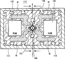
Fig. 5 is the cross-sectional view of X-X along the line;
Fig. 6 is the cross-sectional view of Y-Y along the line;
Fig. 7 illustrates the cross-sectional view that refrigerating unit shown in Fig. 4 is in disassembly status.
Embodiment
Hereinafter, will describe the preferred embodiments of the present invention in detail referring to accompanying drawing.For clarity and conciseness, the known function that is integrated in this and the detailed description of structure have been omitted at this, because it may make theme of the present invention become unclear.
Fig. 2 illustrates the synoptic diagram that is installed in the optical fiber drawing member in the drawing tower.Fig. 2 especially illustrates two refrigerating units that are used for high speed drawing 10 that adopt according to embodiments of the invention in the optical fiber drawing equipment.Yet should be pointed out that according to instruction of the present invention to provide refrigerating unit more than two.Therefore, the number of the refrigerating unit among Fig. 2 should not limit the scope of the invention.
As shown in Figure 2, the technology that is used for drawing optical fiber is carried out along downward vertical direction in proper order at drawing tower (it highly is at least 10m).At first, provide preform P, and be the center with the vertical pivot of drawing tower, it is melted to fully high temperature in smelting furnace 8, is drawn into the fine F1 of single beam then.The diameter of the optical fiber F1 of drawing is by 9 controls of diameter controller and pass refrigerating unit 10 of the present invention, so that optical fiber can be cooled to the proper temperature that is used for applying covering thereon.Refrigerative optical fiber F2 applies with covering when passing applying device 16, and ultraviolet ray (UV) cure polymer that then has been applied to when optical fiber passes UV solidification equipment 18 on the circumferential surface of optical fiber solidifies.
After this technology, pass the optical fiber that solidifies phase place and passed capstan winch 19 and a plurality of deflector roll 22 and 24, then finally be wound on the winding unit 26.Capstan winch 19 provides predetermined drawing force, so that can have the optical fiber of fixed diameter from the preform drawing.Label 26a represents that optical fiber finally is wound up into roll or the spool on it.
Each the optical fiber drawing equipment that is installed in the optical fiber drawing tower keeps horizontal or vertical each other, and has and be not subjected to vibrate or the structure of shock effect.Refrigerating unit especially is used for cooling off equably the optical fiber F1 by drawing.The vertical height of drawing tower shown in the figure surpasses about 10m, and will have the vertical span that surpasses about 10m from the optical fiber of preform P drawing.When with High Temperature And Velocity drawing optical fiber F1, refrigerating unit 10 is carried out and is made optical fiber F1 be cooled to about 40 ℃ function.
Now, will be referring to the detailed structure of Fig. 3 to Fig. 7 description according to refrigerating unit of the present invention.
As shown in Figure 3 and Figure 4, refrigerating unit 10 is used in the high speed drawing of optical fiber (below be referred to as " refrigerating unit "), optical fiber is cooled to be suitable for apply the ideal temperature of the optical fiber of drawing.Should be pointed out that in the drawing tower at least one refrigerating unit can be installed.Refrigerating unit 10 is constructed like this, so that it is opened automatically, closes and controls.Be used for opening automatically, close and the both not shown also not argumentation of device of controlled chilling device, because they are the themes that do not covered by the present invention.Refrigerating unit 10 is equipped with disorderly producer 140 in cooling body 110, thereby makes as cooling agent (He, Ar, N
2) the cold gas scale of construction minimum used.
Fig. 3 illustrates the side-view according to the outward appearance of refrigerating unit of the present invention.In the drawings, the optical fiber that cooled body is hidden is shown.Fig. 4 illustrates four disorderly producers and is used and is installed in according to the state in the refrigerating unit of the present invention.
Referring to Fig. 3, refrigerating unit 10 comprises the separable cooling body of L-R, and it is made of left cooling body part 112 and right cooling body part 114; Top cover labyrinth 120 and lower sealing cover 130, they are separately positioned on the top and bottom of cooling body 110, enter to stop extraneous air, and wherein cooling gas passes sealing cover and supplies in the cooling body; At least one disorderly producer 140, it is placed on the pre-position longitudinally of cooling body 110, imports the molecular motion of the cooling gas of cooling body 110 with further activation.
Disorderly producer 140 usefulness are so that the molecular flow disorder of cooling gas (being helium gas), and described cooling gas is supplied to the inside of the cooling body 110 of whole assembling, thereby cooling efficiency is maximized.Left side cooling end 112 and right side cooling end 114 are respectively arranged with a disorderly producer 140, and at least one disorderly producer is arranged on the vertical of cooling body 110.Notice that disorderly producer is installed in left side cooling end 112 and the right side cooling end 114 with symmetrical manner.When disorderly producer 140 with pass groove S, when being communicated with by the atmosphere of the optical fiber F1 of drawing, optical fiber F1 is influenced by the disorder campaign of the cooling gas that is caused by disorderly producer is direct.
To shown in Figure 7, left and right cooling body part 112 and 114 is supplied with low-temperature cooling water W incessantly as Fig. 5, and water coolant circulates continuously from the predetermined position.Water coolant W absorbs heat from the cooling body 110 that is heated by the optical fiber F1 of drawing, thereby mainly makes the cooling substantially around optical fiber F1.
In addition, left and right cooling body part 112 and 114 is provided with helium gas 146, and described helium gas 146 is supplied to the atmosphere of cooling around optical fiber F1.In a left side and right cooling body part 112 and 114 internal cooling water W and helium gas 146 by the symmetry storage with provide.Water coolant W is provided to the vertically circulation continuously to cooling body and helium gas 146, and to cooling gas being provided and making its surface towards optical fiber by the circumferential direction of the optical fiber F1 of drawing.
Disorderly producer 140 preferably includes cooling fan, and groove S is provided with like this so that the ventilation that is produced by cooling fan 140 produces is disorderly, and be communicated with by the optical fiber F1 of drawing.The ventilation that is caused by cooling fan 140 directly influences optical fiber F1, itself makes the cooling efficiency maximization again.Though the optical fiber by drawing runs at high speed (run),, the aeration flow that is provided towards the circumferential direction of optical fiber F1 by cooling fan 140 directly contacts the cooling efficiency maximizing of helium gas with optical fiber F1 because mixing also with helium gas 146.
In addition, at least one vibration damping anchor clamps 142 be installed in by the optical fiber F1 of drawing vertically, especially between cooling fan 140 and optical fiber F1, thereby use the quality of cooling gas 146 cooling optical fibers of supplying with to keep homogeneity.
Therefore, the cooling gas of fan 140 disorders that are cooled 146 connects (interface) just by the high temperature optical fiber with high speed drawing, and disorderly simultaneously cooling gas contacts, and its polymer motion is in order to cooling optical fibers surface effectively.
Below will describe the operation of the refrigerating unit 10 of structure as mentioned above in detail.
When from preform drawing optical fiber, it is placed in the thawing furnace and has been subjected to preheating and heating process; If (linear speed is about 200~500 meters/minute: mpm) increase tension force is imposed on optical fiber F1, left and right cooling body part 112 and 114 is combined together to form single main body to the drawing speed of optical fiber F1, and promptly cooling body 110.Simultaneously, loam cake 120 and lower cover 130 macrogamys are to cooling body 140, and then cooling gas 146 is fed into cooling body 110.After this technology, if basically tension and reached about 700~1000mpm by the linear speed of the optical fiber of drawing, make disorderly producer 140 runnings.Disorderly producer 140 activates the molecular motion of cooling gas 146 gradually, and it is disorderly that it is produced, the cooling gas of supplying with by groove S absorb from the surface of optical fiber F1 and transferred heat to cooling body 110 surfaces.Notice that set groove S passes the inwall of cooling body 110 and perpendicular to being extended by the optical fiber F1 of drawing.
After this, if optical fiber is cut off and stops, cooling body partly will move to make automatically and be separated from each other, thereby open cooling body, and drawing process will be terminated, and not need independent flushing (flush) step.Preferably, by the vibration damping anchor clamps 142 that vertically are arranged in the cooling body 110 of the optical fiber F1 of drawing the quality by the cooling gas cooling optical fibers is kept evenly by the edge.
The drawing tower can be provided with at least one according to refrigerating unit of the present invention, and preferably adopts two refrigerating units 10, as shown in Figure 2.
Understand from above-mentioned, use the high speed drawing of disorderly producer to improve optical fiber output according to refrigerating unit of the present invention.And by using disorderly producer, the present invention can reduce the cold gas scale of construction that is consumed, thereby has improved the competitiveness of cost.
Though illustrate and described the present invention referring to some preferred embodiment of the present invention, yet those skilled in the art will understand, wherein can carry out the various variations on form and the details, and not depart from by the defined the spirit and scope of the present invention of appending claims.
Claims (11)
1, a kind of refrigerating unit that adopts in the optical fiber drawing process comprises:
Cooling body, this cooling body have left cooling body part and the right cooling body part along the longitudinal extension of the optical fiber of drawing, and described cooling body is closed by sealing cover, and cooling gas passes described sealing cover and is fed in the described cooling body;
At least one disorderly producer, this disorder producer is installed in the described cooling body, with the optical fiber around described drawing, be used to activate the molecule that supplies to the intravital described cooling gas of described cooling and flow, and described disorderly producer is made up of cooling fan; With
At least one vibration damping anchor clamps, described vibration damping anchor clamps are between the optical fiber of described disorderly producer and described drawing, to keep the quality of the described optical fiber of cooling equably.
2, refrigerating unit according to claim 1, wherein said refrigerating unit also comprise two or more disorderly producers.
3, refrigerating unit according to claim 1, wherein said disorderly producer vertically is mounted to stacked structure along cooling body.
4, refrigerating unit according to claim 1, wherein at least one vibration damping anchor clamps is placed by the optical fiber of drawing along described.
5, refrigerating unit according to claim 1, wherein said refrigerating unit main body comprises two or more vibration damping anchor clamps.
6, refrigerating unit according to claim 1, wherein said vibration damping anchor clamps are installed in the described cooling body symmetrically.
7, refrigerating unit according to claim 1, wherein said disorderly producer is provided with at least one groove, is used to make the internal communication of described disorderly producer and described cooling body, and the optical fiber of described drawing passes the inside of described cooling body.
8, refrigerating unit according to claim 1, wherein said disorderly producer is installed with symmetric form.
9, refrigerating unit according to claim 1, a wherein said left side and right cooling body part also have been supplied to water coolant.
10, refrigerating unit according to claim 1, a wherein said left side and right cooling body partly are provided with helium gas.
11, refrigerating unit according to claim 1, wherein said disorderly producer comprise that at least one is used to produce disorderly cooling fan.
Applications Claiming Priority (2)
| Application Number | Priority Date | Filing Date | Title |
|---|---|---|---|
| KR10-2002-0041926A KR100493085B1 (en) | 2002-07-18 | 2002-07-18 | Cooling device for high-speed drawing |
| KR41926/2002 | 2002-07-18 |
Publications (2)
| Publication Number | Publication Date |
|---|---|
| CN1475452A CN1475452A (en) | 2004-02-18 |
| CN1293009C true CN1293009C (en) | 2007-01-03 |
Family
ID=29775022
Family Applications (1)
| Application Number | Title | Priority Date | Filing Date |
|---|---|---|---|
| CNB03178464XA Expired - Fee Related CN1293009C (en) | 2002-07-18 | 2003-07-16 | Cooling device used for rapid drawing |
Country Status (5)
| Country | Link |
|---|---|
| US (1) | US20040011084A1 (en) |
| EP (1) | EP1382581B1 (en) |
| JP (1) | JP3968061B2 (en) |
| KR (1) | KR100493085B1 (en) |
| CN (1) | CN1293009C (en) |
Cited By (1)
| Publication number | Priority date | Publication date | Assignee | Title |
|---|---|---|---|---|
| CN103339073A (en) * | 2010-11-08 | 2013-10-02 | 康稳法国公司 | Improved optical fiber cooling device |
Families Citing this family (7)
| Publication number | Priority date | Publication date | Assignee | Title |
|---|---|---|---|---|
| CA2537751A1 (en) * | 2005-02-28 | 2006-08-28 | Weatherford/Lamb, Inc. | Furnace and process for drawing radiation resistant optical fiber |
| US8230704B2 (en) * | 2009-10-28 | 2012-07-31 | Corning Incorporated | Systems and methods for cooling optical fiber |
| CN104944761A (en) * | 2015-05-29 | 2015-09-30 | 成都亨通光通信有限公司 | Optical fiber production method with characteristic of optical fiber cable manufacturing quality benefiting |
| DE102017108549A1 (en) * | 2017-04-21 | 2018-10-25 | Schott Ag | Apparatus and method for cooling a glass strand fabricated by means of tube drawing |
| JP7266788B2 (en) * | 2019-09-09 | 2023-05-01 | 住友電気工業株式会社 | Optical fiber manufacturing method and optical fiber cooling device |
| CN113816598A (en) * | 2021-10-13 | 2021-12-21 | 成都中住光纤有限公司 | Cooling device for reducing helium flow |
| CN116081961B (en) * | 2023-02-06 | 2025-04-11 | 华能(泰安)光电科技有限公司 | Optical fiber coating cooling device |
Citations (10)
| Publication number | Priority date | Publication date | Assignee | Title |
|---|---|---|---|---|
| JPS6065747A (en) * | 1983-09-16 | 1985-04-15 | Furukawa Electric Co Ltd:The | Cooling of optical fiber |
| CN85101537A (en) * | 1985-04-01 | 1986-10-29 | 菲利浦光灯制造公司 | Fibre-optic manufacture method and equipment with protective coating |
| US4913715A (en) * | 1984-09-13 | 1990-04-03 | U.S. Philips Corp. | Method of manufacturing an optical fiber having a protective coating |
| GB2226310A (en) * | 1988-12-23 | 1990-06-27 | Stc Plc | Optical fibre manufacture |
| US4966615A (en) * | 1987-09-08 | 1990-10-30 | Oy Nokia Ab | Apparatus for cooling an optical fiber |
| DE4215475A1 (en) * | 1992-05-11 | 1993-11-18 | Rheydt Kabelwerk Ag | Optical fibre drawing from preform - involves fibre cooling, with gas stream controlled by gas pressure cushion |
| JPH06219789A (en) * | 1993-01-27 | 1994-08-09 | Furukawa Electric Co Ltd:The | Optical fiber manufacturing method |
| US5568728A (en) * | 1994-03-05 | 1996-10-29 | Northern Telecom Limited | Filament cooler |
| CN1301674A (en) * | 1999-12-30 | 2001-07-04 | 阿尔卡塔尔公司 | Cooling method for fibre forming process in optic fiber |
| CN1338441A (en) * | 2000-08-16 | 2002-03-06 | 阿尔卡塔尔公司 | Optical fiber multi-chamber cooling apparatus and process |
Family Cites Families (5)
| Publication number | Priority date | Publication date | Assignee | Title |
|---|---|---|---|---|
| JPH02164739A (en) | 1988-12-19 | 1990-06-25 | Sumitomo Electric Ind Ltd | Cooling device of optical fiber |
| DE3919953A1 (en) * | 1989-06-19 | 1990-12-20 | Rheydt Kabelwerk Ag | Cooling device for drawn light-conducting fibre - has internal body which can be opened into two halves surrounded by outer coolant body |
| JPH08310826A (en) * | 1995-05-12 | 1996-11-26 | Fujikura Ltd | Optical fiber preform stretching method |
| US6125638A (en) * | 1998-08-21 | 2000-10-03 | The Boc Group, Inc. | Optical fiber cooling process |
| US20030205066A1 (en) * | 2002-03-25 | 2003-11-06 | Ghani M. Usman | Method and apparatus for efficient cooling of optical fiber during its manufacture |
-
2002
- 2002-07-18 KR KR10-2002-0041926A patent/KR100493085B1/en not_active Expired - Fee Related
-
2003
- 2003-07-08 US US10/615,711 patent/US20040011084A1/en not_active Abandoned
- 2003-07-16 CN CNB03178464XA patent/CN1293009C/en not_active Expired - Fee Related
- 2003-07-18 JP JP2003276650A patent/JP3968061B2/en not_active Expired - Fee Related
- 2003-07-18 EP EP03015672.3A patent/EP1382581B1/en not_active Expired - Lifetime
Patent Citations (10)
| Publication number | Priority date | Publication date | Assignee | Title |
|---|---|---|---|---|
| JPS6065747A (en) * | 1983-09-16 | 1985-04-15 | Furukawa Electric Co Ltd:The | Cooling of optical fiber |
| US4913715A (en) * | 1984-09-13 | 1990-04-03 | U.S. Philips Corp. | Method of manufacturing an optical fiber having a protective coating |
| CN85101537A (en) * | 1985-04-01 | 1986-10-29 | 菲利浦光灯制造公司 | Fibre-optic manufacture method and equipment with protective coating |
| US4966615A (en) * | 1987-09-08 | 1990-10-30 | Oy Nokia Ab | Apparatus for cooling an optical fiber |
| GB2226310A (en) * | 1988-12-23 | 1990-06-27 | Stc Plc | Optical fibre manufacture |
| DE4215475A1 (en) * | 1992-05-11 | 1993-11-18 | Rheydt Kabelwerk Ag | Optical fibre drawing from preform - involves fibre cooling, with gas stream controlled by gas pressure cushion |
| JPH06219789A (en) * | 1993-01-27 | 1994-08-09 | Furukawa Electric Co Ltd:The | Optical fiber manufacturing method |
| US5568728A (en) * | 1994-03-05 | 1996-10-29 | Northern Telecom Limited | Filament cooler |
| CN1301674A (en) * | 1999-12-30 | 2001-07-04 | 阿尔卡塔尔公司 | Cooling method for fibre forming process in optic fiber |
| CN1338441A (en) * | 2000-08-16 | 2002-03-06 | 阿尔卡塔尔公司 | Optical fiber multi-chamber cooling apparatus and process |
Cited By (1)
| Publication number | Priority date | Publication date | Assignee | Title |
|---|---|---|---|---|
| CN103339073A (en) * | 2010-11-08 | 2013-10-02 | 康稳法国公司 | Improved optical fiber cooling device |
Also Published As
| Publication number | Publication date |
|---|---|
| US20040011084A1 (en) | 2004-01-22 |
| JP2004051480A (en) | 2004-02-19 |
| CN1475452A (en) | 2004-02-18 |
| EP1382581A1 (en) | 2004-01-21 |
| JP3968061B2 (en) | 2007-08-29 |
| KR20040008311A (en) | 2004-01-31 |
| EP1382581B1 (en) | 2017-01-04 |
| KR100493085B1 (en) | 2005-06-03 |
Similar Documents
| Publication | Publication Date | Title |
|---|---|---|
| CN1293009C (en) | Cooling device used for rapid drawing | |
| CN102245522B (en) | The manufacture method of optical fiber cable | |
| AU741066B2 (en) | Method and apparatus for cooling optical fibers | |
| CN209024410U (en) | A kind of ribbonized optical fibers wire-drawing mechanism | |
| CN86103285A (en) | Method and device for coating fiber | |
| CN111690994A (en) | Preparation method of graphene-polyester nano composite fiber | |
| CN115083695A (en) | Automatic coating device and automatic coating method for wire and cable insulating layer | |
| CN114775077B (en) | A bio-based composite monofilament spinning and winding device | |
| CN106400141A (en) | Static-pressure melting spinning apparatus | |
| CN116081961B (en) | Optical fiber coating cooling device | |
| CN116002969B (en) | Quartz glass rod drawing device and method | |
| CA2098268A1 (en) | Optical fiber production method and production apparatus thereof | |
| CN201109806Y (en) | Blast cooling apparatus for chemical fibre filament yarn melt spinning loop | |
| CN117476287B (en) | Environment-friendly high-voltage cable preparation device and high-voltage cable | |
| CN108385181A (en) | Combination plant is led in a kind of spinning of monofilament | |
| CN116988173A (en) | Air jet spinning device for continuous fiber preparation | |
| CN218026472U (en) | Bio-based composite monofilament spinning winding device | |
| CN113981579B (en) | Efficient texturing processing device and production process for polyamide yarns | |
| KR100459570B1 (en) | Cooling device with sealing cap for high-speed drawing in fiber drawing process | |
| CN120287547A (en) | Cable extrusion device | |
| CN119748870A (en) | A continuous fiber prepreg production line for 3D printing | |
| CN222455329U (en) | Chemical fiber side-blowing cooling device | |
| CN112174513A (en) | High-speed optical fiber drawing system | |
| CN110181791A (en) | A kind of dry type Loose tube excess length control device | |
| CN118756361B (en) | Spinning lapping production system |
Legal Events
| Date | Code | Title | Description |
|---|---|---|---|
| C06 | Publication | ||
| PB01 | Publication | ||
| C10 | Entry into substantive examination | ||
| SE01 | Entry into force of request for substantive examination | ||
| C14 | Grant of patent or utility model | ||
| GR01 | Patent grant | ||
| CF01 | Termination of patent right due to non-payment of annual fee | ||
| CF01 | Termination of patent right due to non-payment of annual fee |
Granted publication date: 20070103 Termination date: 20180716 |