CN1296609C - Crosshead large two-stroke internal combustion engine - Google Patents
Crosshead large two-stroke internal combustion engine Download PDFInfo
- Publication number
- CN1296609C CN1296609C CNB031369138A CN03136913A CN1296609C CN 1296609 C CN1296609 C CN 1296609C CN B031369138 A CNB031369138 A CN B031369138A CN 03136913 A CN03136913 A CN 03136913A CN 1296609 C CN1296609 C CN 1296609C
- Authority
- CN
- China
- Prior art keywords
- steel plate
- explosive motor
- cylinder
- sidewall
- upper steel
- Prior art date
- Legal status (The legal status is an assumption and is not a legal conclusion. Google has not performed a legal analysis and makes no representation as to the accuracy of the status listed.)
- Expired - Fee Related
Links
Images





Classifications
-
- F—MECHANICAL ENGINEERING; LIGHTING; HEATING; WEAPONS; BLASTING
- F02—COMBUSTION ENGINES; HOT-GAS OR COMBUSTION-PRODUCT ENGINE PLANTS
- F02B—INTERNAL-COMBUSTION PISTON ENGINES; COMBUSTION ENGINES IN GENERAL
- F02B75/00—Other engines
- F02B75/16—Engines characterised by number of cylinders, e.g. single-cylinder engines
- F02B75/18—Multi-cylinder engines
- F02B75/22—Multi-cylinder engines with cylinders in V, fan, or star arrangement
-
- F—MECHANICAL ENGINEERING; LIGHTING; HEATING; WEAPONS; BLASTING
- F02—COMBUSTION ENGINES; HOT-GAS OR COMBUSTION-PRODUCT ENGINE PLANTS
- F02B—INTERNAL-COMBUSTION PISTON ENGINES; COMBUSTION ENGINES IN GENERAL
- F02B75/00—Other engines
- F02B75/02—Engines characterised by their cycles, e.g. six-stroke
- F02B2075/022—Engines characterised by their cycles, e.g. six-stroke having less than six strokes per cycle
- F02B2075/025—Engines characterised by their cycles, e.g. six-stroke having less than six strokes per cycle two
Landscapes
- Engineering & Computer Science (AREA)
- Chemical & Material Sciences (AREA)
- Combustion & Propulsion (AREA)
- Mechanical Engineering (AREA)
- General Engineering & Computer Science (AREA)
- Cylinder Crankcases Of Internal Combustion Engines (AREA)
- Pistons, Piston Rings, And Cylinders (AREA)
Abstract
本发明公开一种十字头型大型双冲程内燃发动机。发动机包括基底(7)、A形曲轴箱结构(2)和汽缸结构(30,30’),基底上设有支撑曲轴(22)的主轴承,曲轴箱结构安装在基底上并设有支撑用于十字头的导引板(13)的横向支肋(9),汽缸结构安装在曲轴箱结构上,曲轴箱结构通过拉杆螺栓(16)与基底夹紧在一起。汽缸结构(30,30’)由焊接结构形成,包括大致为平板形的上钢板(31),上钢板上设有容纳和支撑汽缸衬套(6)的圆形开口(39)。汽缸结构还设有两个大致平行于曲轴(22)延伸的外侧壁(32,33)、至少两个与侧壁相互连接的横向壁(34,35,36)。汽缸结构的侧壁(32,33)大约设置在引导片(13)的正上方而使侧壁支撑在引导板上。

The invention discloses a crosshead type large double-stroke internal combustion engine. The engine includes a base (7), an A-shaped crankcase structure (2) and a cylinder structure (30, 30'). The base is provided with a main bearing supporting the crankshaft (22), and the crankcase structure is installed on the base and provided with a support. On the transverse support rib (9) of the guide plate (13) of the crosshead, the cylinder structure is installed on the crankcase structure, and the crankcase structure is clamped together with the base by tie rod bolts (16). The cylinder structure (30, 30') is formed of a welded structure and includes a generally flat upper steel plate (31) provided with a circular opening (39) for accommodating and supporting the cylinder liner (6). The cylinder structure is also provided with two outer side walls (32, 33) extending substantially parallel to the crankshaft (22), at least two transverse walls (34, 35, 36) interconnecting the side walls. The side walls (32, 33) of the cylinder structure are arranged approximately directly above the guide plate (13) such that the side walls are supported on the guide plate.
Description
技术领域technical field
本发明涉及一种十字头型大型双冲程内燃机,包括具有一个支撑曲轴的主轴承的基底、一个安装在基底上的A形曲轴箱结构和一个安装于A形曲轴箱结构的汽缸结构,曲轴箱结构与基底通过拉杆螺栓夹紧,所述曲轴箱结构包括用于支撑十字头型的导引片的横向支肋,汽缸结构通过焊接结构形成,包括具有至少一个用于收容和支撑汽缸衬套的圆形开口的大致为平板状的上钢板、两个大致与曲轴平行延伸的外部侧壁和至少两个与侧壁连接的横向壁。汽缸结构形成支撑,以承载汽缸衬套、曲轴箱和净化空气储气室。The present invention relates to a crosshead type large double-stroke internal combustion engine, comprising a base with a main bearing supporting the crankshaft, an A-shaped crankcase structure mounted on the base, and a cylinder structure mounted on the A-shaped crankcase structure, the crankcase The structure and the base are clamped by tie rod bolts, the crankcase structure includes transverse ribs for supporting the crosshead type guide plate, the cylinder structure is formed by welding structure, and includes at least one cylinder liner for receiving and supporting the cylinder liner. A substantially flat upper steel plate of the circular opening, two outer side walls extending substantially parallel to the crankshaft and at least two transverse walls connected to the side walls. The cylinder structure forms the support to carry the cylinder liners, crankcase and purge air reservoir.
背景技术Background technique
从曼B与W狄赛尔公司1999年第二版的“双冲程发动机K98MC项目指南”(“K98MC Project Guide Two-Stroke Engines”2nd edition1999,MAN B&W Diesel A/S)可知,用于大型双冲程内燃机的汽缸结构全部由铸钢制造为用于两个或更多个汽缸的整个汽缸体或用于大型发动机的汽缸单元。凸轮轴箱体与汽缸结构作为一个单元一起铸成。大致为平板形的上钢板具有至少一个圆形开口,用以收容和支撑汽缸衬套,该上钢板安装在汽缸结构的上部。It is known from the "K98MC Project Guide Two-Stroke Engine K98MC Project Guide" ("K98MC Project Guide Two-Stroke Engines" 2nd edition1999, MAN B&W Diesel A/S) of the second edition in 1999 that it is used for large two-stroke engines. The cylinder structure of an internal combustion engine is manufactured entirely from cast steel as a complete cylinder block for two or more cylinders or as a cylinder unit for a large engine. The camshaft housing is cast together with the cylinder structure as a unit. A generally flat upper steel plate has at least one circular opening for receiving and supporting the cylinder liner, the upper steel plate is mounted on the upper part of the cylinder structure.
对于汽缸内径达到50cm的发动机来说,汽缸结构和凸轮轴箱体铸成为一个单元。当汽缸内径在60-70cm之间时,汽缸结构和凸轴箱体通常采用包括两个汽缸的料块制造。对于汽缸内径大于80cm的大型发动机,汽缸结构采用仅包括一个汽缸的料块铸造制成。大型发动机的汽缸结构必须分成几个小单元,否则其重量将超过发动机组装设备内的升降机构的最大支撑重量。而且,目前的铸造工艺也限制了要铸造物体的最大尺寸。通过铸造制成汽缸结构生产工艺相对便宜而且是成熟工艺,大型发动机的汽缸结构的分解会产生附加的生产成本。For engines with cylinder bores up to 50 cm, the cylinder structure and camshaft housing are cast as one unit. When the cylinder bore is between 60-70 cm, the cylinder structure and cam housing are usually manufactured from a block comprising two cylinders. For large engines with a cylinder bore greater than 80 cm, the cylinder structure is cast from a block comprising only one cylinder. The cylinder structure of a large engine must be divided into several small units, otherwise its weight will exceed the maximum support weight of the lifting mechanism in the engine assembly equipment. Furthermore, current casting processes also limit the maximum size of objects to be cast. The production process of making the cylinder structure by casting is relatively cheap and a mature process, and the disassembly of the cylinder structure of a large engine will cause additional production costs.
例如,为了在汽缸结构的上表面加工一个平坦表面,独立的单元需要一个接一个地被提升到平面铣床上。之后,它们被栓接在一起并对汽缸结构进行加工。但是,生产过程要求在汽缸结构自身的加工过程前后、发动机运转测试的前后和在诸如船舶或发电装置等的发动机工作场所进行组装时组装和拆开汽缸结构。相应地,在大型发动机内需要花费相当数量的附加资源,因为在这些步骤中每一个汽缸结构均需要从几个单元中组装和调整,反之亦然。而且,汽缸结构的独立单元之间的连接在组装时必须牢固且精确。这里应用的螺栓连接既昂贵又要使用大量劳动力。For example, in order to machine a flat surface on the upper surface of a cylinder structure, individual units need to be lifted one by one onto a plane milling machine. Afterwards, they are bolted together and the cylinder structure is machined. However, the production process requires that the cylinder structure be assembled and disassembled before and after the machining process of the cylinder structure itself, before and after the engine running test, and during assembly at an engine workplace such as a ship or a power generation facility. Correspondingly, a considerable amount of additional resources is expended in large engines, since in these steps each cylinder structure needs to be assembled and adjusted from several units, and vice versa. Furthermore, the connections between the individual units of the cylinder structure must be strong and precise when assembled. The bolted connections applied here are expensive and labor intensive.
DK 1405/92号专利申请揭示一种十字头型大型双冲程内燃机,包括由焊接板构成的汽缸结构。厚的汽缸结构侧壁设置在曲轴箱结构的外壁正上方,所述厚的侧壁可承受经由拉杆螺栓传递到结构箱体和汽缸结构的巨大且变化的压力。因此,曲轴箱结构的外壁也需要能够承受上述的由拉杆螺栓传递的巨大压力,曲轴箱的外壁也具有相应的厚度。这就导致曲轴箱结构的重量和整个发动机的重量的显著增加。而且,汽缸结构必须横跨曲轴箱结构上部的整个宽度。这就致使汽缸结构相对较大且需要附加纵向延伸的壁以支撑汽缸结构的上钢板。因此,这样的汽缸结构变得相对较重。Patent application DK 1405/92 discloses a large two-stroke internal combustion engine of the crosshead type, comprising a cylinder structure made of welded plates. Thick cylinder structure side walls are provided directly above the outer walls of the crankcase structure, which thick side walls can withstand the enormous and varying pressures transmitted to the structural case and cylinder structure via stay bolts. Therefore, the outer wall of the crankcase structure also needs to be able to withstand the above-mentioned huge pressure transmitted by the tie rod bolts, and the outer wall of the crankcase also has a corresponding thickness. This leads to a considerable increase in the weight of the crankcase structure and the weight of the engine as a whole. Furthermore, the cylinder structure must span the entire width of the upper part of the crankcase structure. This results in a relatively large cylinder structure and requires an additional longitudinally extending wall to support the upper steel plate of the cylinder structure. Therefore, such a cylinder structure becomes relatively heavy.
发明内容Contents of the invention
本发明目的在于提供一种克服上述缺陷的十字头型大型双冲程内燃发动机。本发明目的是通过提供包括基底、A形曲轴箱结构和汽缸结构的十字头型双冲程内燃发动机实现的,基底上设有支撑曲轴的主轴承,A形曲轴箱结构安装在基底上且其上设有横向支肋用以支撑用于十字头的导引片,汽缸结构安装在A形曲轴箱,曲轴箱通过拉杆螺栓与基底夹紧在一起,汽缸结构由焊接结构形成,包括大致为平面的上钢板,上钢板上设有至少一个圆形开口以收容和支撑汽缸衬套,两个外部侧壁大致平行于曲轴延伸,至少两个横向壁与侧壁相互连接,其中,侧壁设置在导引片的正上方以使侧壁支撑在导引片上。The object of the present invention is to provide a crosshead type large-scale two-stroke internal combustion engine that overcomes the above-mentioned defects. The object of the present invention is achieved by providing a crosshead type two-stroke internal combustion engine comprising a base, an A-shaped crankcase structure and a cylinder structure, the base is provided with a main bearing supporting the crankshaft, the A-shaped crankcase structure is mounted on the base and on which There are transverse ribs to support the guide plates for the crosshead. The cylinder structure is installed in the A-shaped crankcase. The crankcase is clamped together with the base by tie rod bolts. The cylinder structure is formed by welded structure, including the roughly planar The upper steel plate is provided with at least one circular opening to accommodate and support the cylinder liner, the two outer side walls extend approximately parallel to the crankshaft, and at least two transverse walls are connected to the side walls, wherein the side walls are arranged in the guide directly above the guide tab so that the side walls rest on the guide tab.
通过以钢板的焊接结构代替铸钢结构,可以构造出较轻的汽缸结构。本发明的用以支撑大型发动机的若干个汽缸衬套的整体汽缸结构也可以由现有的负载升降机构举起。而且,通过将厚的汽缸结构侧壁设置在曲轴箱结构的导引片的正上方,侧壁支撑在导引片上,当发动机在运转时,在整个发动机结构具有所要求的刚性来承受通过拉杆螺栓传递到结构箱体和汽缸结构上的巨大且变化的压力的同时,整个发动机结构可以轻型地实现。By replacing the cast steel structure with a welded structure of steel plates, a lighter cylinder structure can be constructed. The integral cylinder structure of the present invention to support several cylinder liners of a large engine can also be lifted by existing load lifting mechanisms. Furthermore, by placing the thick cylinder structure side walls directly above the guide tabs of the crankcase structure on which the side walls rest, when the engine is running, the entire engine structure has the required rigidity to bear The entire engine structure can be realized lightweight while the bolts transmit huge and varying pressures to the structural box and cylinder structure.
侧壁和所述支撑导引片可以承受通过拉杆螺栓作用在发动机机构上的大部分力,从而剩余结构可采用轻巧的尺寸。The side walls and said support guides take up most of the forces acting on the engine mechanism via the stay bolts, so that the remaining structure can be of compact size.
侧壁和所述的横向壁可以焊接到一起,从而形成一个在上钢板所在平面具有矩形横截面的中空体。The side walls and said transverse walls may be welded together so as to form a hollow body with a rectangular cross-section in the plane of the upper steel plate.
侧壁可相互倾斜设置,优选的角度是相对上钢板成0-10度角,更优选的是相对上钢板成2-10度角。这就减少了侧壁上部和圆形开口之间的距离。因此,在拉杆螺栓作用的力的影响下,上钢板会弯曲的较小。从而降低了上钢板和侧壁之间的接点处的应力水平。The side walls can be arranged inclined to each other, preferably at an angle of 0-10 degrees relative to the upper steel plate, more preferably at an angle of 2-10 degrees relative to the upper steel plate. This reduces the distance between the upper part of the side wall and the circular opening. Therefore, under the influence of the forces acting on the tie rods, the upper steel plate will bend less. The stress level at the joint between the upper steel plate and the side wall is thereby reduced.
横向壁可以设置在每个汽缸之间,将矩形截面分成包围每个汽缸的大致为方形的截面。上钢板就支撑在每个容纳汽缸衬套的凹口处。Transverse walls may be provided between each cylinder, dividing the rectangular section into generally square sections surrounding each cylinder. An upper steel plate rests on each notch that accommodates the cylinder liner.
为提高每个凹口处的上钢板的支撑力,大致为方形的截面可以再设置另外四个壁以形成在上钢板所在平面具有八边形横截面的中空体。In order to improve the supporting force of the upper steel plate at each notch, the roughly square cross-section can be further provided with four other walls to form a hollow body with an octagonal cross-section in the plane where the upper steel plate is located.
汽缸结构还可设置有大致垂直于上述侧壁的伸垫板,优选的是在所述横向壁所在的平面内设置该伸垫板,至少其中一个伸垫板与其中一个侧壁和一个加强板形成第一中空轮廓,其中一个拉杆螺栓伸入到该第一中空轮廓中。The cylinder structure can also be provided with extension plates substantially perpendicular to the above-mentioned side walls, preferably in the plane where the transverse wall is located, at least one of the extension plates is connected with one of the side walls and a reinforcement plate A first hollow profile is formed, into which a stay bolt protrudes.
A形曲轴结构也可设置一个第二中空轮廓,拉杆螺栓伸入到这个中空轮廓中。该第二中空轮廓由横向支肋与其中一个导引片和一个加强板形成。The A-shaped crankshaft configuration can also be provided with a second hollow profile into which the stay bolts protrude. The second hollow profile is formed by transverse ribs with one of the guide pieces and one of the reinforcing plates.
优选地,第一中空轮廓大约设在第二中空轮廓正上方,使得第一中空轮廓支撑在第二中空轮廓上。因此,这些中空轮廓形成该结构的一个整体部分,以承受通过拉杆螺栓传递到结构箱体和汽缸结构上的巨大且变化的压力。Preferably, the first hollow profile is arranged approximately directly above the second hollow profile, so that the first hollow profile rests on the second hollow profile. These hollow profiles thus form an integral part of the structure to withstand the enormous and varying pressures transmitted to the structural box and cylinder structure via stay bolts.
由于实用的原因,第一中空轮廓和第二中空轮廓可以具有大致为三角形的截面。For practical reasons, the first hollow profile and the second hollow profile may have a substantially triangular cross-section.
由拉杆螺栓从汽缸衬套向侧壁传递的波动的力引起的上钢板的弯曲运动使得在上钢板和侧壁的连接处存在潜在的疲劳问题。降低上钢板和侧壁间接点处应力的一个方式是在上钢板底侧邻近焊接处设置一个具有弧形横向截面的缺口,优选该截面为弧形,最好是半圆形、半椭圆形或其他相似形状。这就是冲孔效应,这样扩大的疲劳问题就可在很大程度上避免了。The bending motion of the upper plate caused by the fluctuating force transmitted by the stay bolts from the cylinder liner to the sidewall creates a potential fatigue problem at the junction of the upper plate and the sidewall. One way to reduce the stress at the joint between the upper steel plate and the side wall is to provide a notch with an arc-shaped transverse cross-section on the bottom side of the upper steel plate adjacent to the weld, preferably the cross-section is arc-shaped, preferably semi-circular, semi-elliptical or other similar shapes. This is the punching effect, so that the fatigue problem of enlargement can be avoided to a large extent.
在上钢板和侧壁连接处的疲劳问题也可由通过以圆角焊接接点连接上钢板与承重壁的钢板来减少,在加工时可在圆角焊接接点、上钢板和侧壁的连接处开设一个槽。Fatigue problems at the connection between the upper steel plate and the side wall can also be reduced by connecting the upper steel plate and the steel plate of the load-bearing wall with fillet welded joints. groove.
汽缸结构还包括由钢板形成的底板,其上设有容纳密气箱的环形开口。The cylinder structure also includes a base plate formed of steel plate on which is provided an annular opening for receiving the airtight box.
为获得更高刚性和强度的汽缸结构,侧壁和/或所述横向壁可以由钢板制成,最好是轧制钢板。To obtain a higher rigidity and strength of the cylinder structure, the side walls and/or said transverse walls may be made of sheet steel, preferably rolled sheet steel.
本发明汽缸结构的其他目的、技术特征、优点及性能可以从下面的详细描述中更显而易见。Other purposes, technical features, advantages and performances of the cylinder structure of the present invention will be more apparent from the following detailed description.
附图说明Description of drawings
在下文中,将参照附图中所示的具体实施方式对本发明进行更详细地描述,其中In the following, the invention will be described in more detail with reference to specific embodiments shown in the accompanying drawings, in which
图1为现有的发动机的剖视图;Fig. 1 is the sectional view of existing engine;
图1a发动机的剖视图;Figure 1a cutaway view of the engine;
图1b为图1发动机沿Ib-Ib线的局部剖视放大图;Fig. 1b is the partial sectional enlarged view of Fig. 1 engine along the Ib-Ib line;
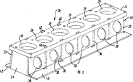
图2为汽缸结构的立体图;Fig. 2 is the perspective view of cylinder structure;
图3为汽缸结构上部的局部剖视图;Fig. 3 is a partial sectional view of the upper part of the cylinder structure;
图3a和3b是不同结构的汽缸结构不同结构的剖视图;Fig. 3 a and 3b are the cross-sectional views of different structures of cylinder structures of different structures;
图4为安装在汽缸结构上的净化空气储气室的立体图;Fig. 4 is the perspective view of the purified air storage chamber installed on the cylinder structure;
图5为净化空气储气室和汽缸结构的详细横断面视图;Fig. 5 is the detailed cross-sectional view of clean air storage chamber and cylinder structure;
图5a为具有减压缺口的焊缝的详细视图;Figure 5a is a detailed view of a weld with a relief notch;
图5b为具有减压槽的焊缝的详细视图;Figure 5b is a detailed view of a weld with relief grooves;
图6为不同结构的汽缸结构和净化空气储气室更详细的横断面视图;和Fig. 6 is a more detailed cross-sectional view of cylinder structures and purge air reservoirs of different configurations; and
图7为汽缸结构和净化空气储气室显示组合单元外部尺寸的示意图。Fig. 7 is a schematic diagram showing the external dimensions of the combined unit of the cylinder structure and the purified air storage chamber.
具体实施方式Detailed ways
在下文的详细描述中,将通过优选的实施方式对本发明进行描述。图1揭示一种现有的比本发明发动机更高更宽的发动机。In the following detailed description, the present invention will be described by way of preferred embodiments. Figure 1 discloses an existing engine which is taller and wider than the engine of the present invention.
图1a揭示一种设置在基座7上的大型12缸双冲程直流净化柴油发动机1,基座7具有用于曲轴22的主轴承。为了便于生产,基座7分为若干合适尺寸的部分。其由具有铸钢轴承支座的高焊接纵梁和焊接横梁组成。焊接而成的A形曲轴箱结构2安装在基座7上。曲轴箱结构在每个汽缸之间设有以横向板9形式设置的支肋,横向板9与曲轴箱结构2上纵长延伸的外壁10互相连接,且横向板9自A形曲轴箱结构2的顶部向底部延伸以增加曲轴箱结构2的横向刚性。FIG. 1 a discloses a large 12-cylinder two-stroke straight-line purified
用以承担作用于十字头21上的力的竖直导引片13安装在横向板9上,例如通过焊接而安装。两个导引片13横向相对安装在内部横向板9的两侧。每一导引片13的后侧由竖直延伸的附加壁14支撑,附加壁14连接导引片和横向板9。如图示,附加壁14可以包括与横向板成锐角设置的平板元件,但也可以使用具有水平四分之一圆周或四分之一椭圆周部分的附加壁14,即附加壁14在横向板9上大致成直角延伸。导引片13、附加壁14和横向板9形成一收容拉杆螺栓且具有高扭转刚性的中空轮廓。
如图4所示,两个汽缸结构30,30’呈一直线安装在A形曲轴结构2的顶部。每一汽缸结构30,30’支撑发动机1的六个汽缸衬套6。当然也可以采用其他结构,如具有三个汽缸结构的发动机,或者是有十一个汽缸的发动机,该发动机包括一个具有五个汽缸的汽缸结构和一个具有六个汽缸的汽缸结构。所述汽缸衬套6由合金铸铁制造。汽缸衬套6的顶部上设有冷却孔,冷却孔内有短冷却套管。汽缸衬套6上设有排气孔和用于汽缸润滑的钻孔。汽缸结构30,30’一侧支撑凸轮轴箱体3。净化空气储气室4沿着汽缸结构30,30’的另一侧设置。净化空气储气室4支撑对净化空气加压的涡轮增压器单元8,废气接收器11平衡各个汽缸内的波动的压力。涡轮增压器8的压缩机经过空气过滤器从发动机室内吸取空气,被压缩的空气通过为多个涡轮增压器工作的净化空气冷却器进行冷却。净化空气冷却器设有水雾制动器提供,该制动器防止空气中的冷凝的水被带到净化空气储气室和燃烧腔内。As shown in Fig. 4, two
请参照图2、图3所示,将详细描述汽缸结构30,其中汽缸结构30’与汽缸结构30完全相同。汽缸结构30包括两个纵向延伸而形成汽缸30的两侧壁32、33的钢板。侧壁32、33通过横向延伸而形成前、后壁34、35的钢板相互连接。侧壁32、33及前、后壁34、35焊接在一起,以形成具有大致矩形截面的中空结构。前、后壁34、35也可以相互倾斜以减轻结构的重量。附加的横向延伸的钢板36设置在每个汽缸之间,因此将汽缸结构的矩形截面分隔成方形部分。附加的横向钢板36焊接到汽缸结构的侧壁32、33上。如图3a所示,根据本发明的另一个较佳实施例,每一个汽缸还设有四个从侧壁向附加的板侧成45角延伸的钢板37,因此,使得汽缸结构的内截面大致成八边形。Referring to Fig. 2 and Fig. 3, the
汽缸结构可由普通钢板或锭铁制成。根据本发明一个较佳实施例,制造汽缸结构的钢板是轧制钢板。上钢板可以由其他可焊接的材料制成,例如铸钢。The cylinder structure can be made of ordinary steel plate or ingot iron. According to a preferred embodiment of the present invention, the steel plate for manufacturing the cylinder structure is a rolled steel plate. The upper steel plate can be made of other weldable materials, such as cast steel.
上钢板31上设有圆形开口39以容纳和支撑汽缸衬套6,上钢板31焊接到形成侧壁32、33、前壁34、后壁35和附加的横向延伸的钢板36的钢板上。侧壁32上设有开口38以使每个汽缸允许净化空气进入汽缸结构30内。上钢板31在其纵向延伸的边上还设有密集的成对的孔40以容纳拉杆螺栓16。A
如图3所示,本发明较佳实施例中,侧壁32、33相互倾斜。因此,侧壁32、33在汽缸结构30顶部的距离小于其在汽缸结构30底部的侧壁32、33之间的距离。上钢板31与侧壁32、33间的夹角优选的为2~10度,但也可以选为0~20度。通过侧壁32、33彼此相向倾斜的设置,在发动机运转过程中,由于较大的变化的力通过汽缸衬套6和拉杆螺栓16施加到上钢板31上而使上钢板弯曲所引起的在上钢板31与侧壁32、33间的焊接接点处的机械应力得以降低。As shown in Fig. 3, in a preferred embodiment of the present invention, the
如图5及图5a所示的另一优选的实施方式,侧壁32、33相对上钢板31成直角设置。通过穿过焊缝设置的缺口43、44,侧壁焊接接点的机械应力降低。缺口43、44具有半圆形截面。此截面形状也可选择为半椭圆形或其他相似形状。In another preferred embodiment shown in FIG. 5 and FIG. 5 a , the
如图5b所示本发明的另一优选的实施方式,上钢板31与侧壁32、33通过圆角焊接接点48连接。圆角焊接接点48和侧壁32、33的接合处,及圆角焊接接点48和上钢板31的接合处,例如通过研磨而制造出大致为半圆形的槽49,49’,以减小圆角焊接接点48和对应钢板31之间机械应力。In another preferred embodiment of the present invention as shown in FIG. 5 b , the
从侧壁32、33底部水平延伸出底座凸缘45。侧壁33上焊接有竖直延伸且面向凸轮轴箱3设置的肋条46。用以安装到凸轮轴箱的凸缘47焊接到肋条46上。支撑板53焊接到凸缘47的末端和侧壁33上以形成容纳拉杆螺栓的三角形轮廓。对于没有凸轮轴的发动机,支撑板就直接焊接到壁33和肋条46上。A
横向延伸的伸垫板50焊接到面对净化空气储气室4的侧壁32上。伸垫板50上设有开口51以允许净化空气的流动。形成净化空气储气室顶壁的平板52焊接在伸垫板50和上钢板31之间。加强板53从每一伸垫板50的两侧成锐角向侧壁32延伸,以在伸垫板50的任一侧形成一个截面大致为三角形的中空轮廓。伸垫板50、加强板53和侧壁32一起形成一个具有高扭转抗压刚度的中空轮廓,所述中空轮廓里容纳拉杆螺栓16。A laterally extending
大致为方形的底板54焊接到汽缸结构30的内表面上。用以容纳活塞杆的密气箱的环形凸缘55焊接到底板54中央的对应开口处。A generally
汽缸结构30,30’和基座7通过成对密集设置的拉杆螺栓夹紧,拉杆螺栓16设置在汽缸结构的中空轮廓和A形曲轴箱结构2的中空轮廓内,且从汽缸结构30,30’上钢板31延伸到A形曲轴箱结构2的底部。且侧壁(32,33)位于导引片(13)的大致正上方的位置。当发动机工作时,这些中空轮廓就作为拉杆螺栓的导槽,向汽缸结构30,30’和A形曲轴箱结构2的箱盒提供所需的抗压刚度以经得住拉杆螺栓16向曲轴箱结构2的箱盒及汽缸结构30,30’传递的大的、变化的压力。拉杆螺栓16的低端被合适地紧固在基座7上部的螺纹孔内。优选的,汽缸结构30,30’的中空轮廓和曲轴箱结构2的中空结构具有相同的截面而且相互上下设置。如图3所示,在凸轮轴箱体侧边,汽缸结构30,30’的中空结构可以被凸缘47断开而安装在凸轮轴箱体3上。The
如图4所示,形成净化空气储气室4部分的C形钢板56焊接在伸垫板50之间。净化空气储气室4的内部空间因此被封闭起来。因此,汽缸结构30,30’的侧壁32也即为净化空气储气室4的侧壁。通过侧壁32即为汽缸结构30,30’的侧壁也是净化空气储气室4的侧壁,从而使汽缸结构30,30’与净化空气储气室4成为一个结构紧湊的单元。本发明还有一个优点在于可以使涡轮增压器8放置地低一些,从而废气接收器11也可以放低设置,从而使发动机1的整体高度变小。As shown in FIG. 4 , the C-shaped
废气接收器11由设置在伸垫板50上的托架63支撑。涡轮增压器8和废气接收器11的相对较低位置增加了整个废气接收器装置的固有频率。由于废气接收器11刚度的增加,可以将废气接收器11分成几个单元以降低制造成本。The exhaust receiver 11 is supported by a
净化空气储气室4由不同部分组成。每一个汽缸结构均包括一个或两个专用部分57,以容纳涡轮增压器8和冷却箱58。涡轮增压器支撑部分57为焊接设计,包括上平板和设置在其低部用以接收经过冷却器的空气的开口。冷却箱栓接或焊接到伸垫板上,其上设有带开口而用以接收经过涡轮增压器的压缩空气的上钢板。涡轮增压器8的凸缘栓接到冷却箱58的上钢板。热交换器形式的内部冷却器设置在冷却箱的内部。冷却箱可以横跨净化空气储气室的几个部分,并服务和支撑不止一个涡轮增压器(未图示)。净化空气储气室4的另一个专用部分60包括一个用于辅助鼓风机61的进气口。冷却箱58可成形为具有扩散体部分的形状,从而辅助鼓风机作为带有叶轮的电机安装在扩散体内部,辅助鼓风机以平行于涡轮增压器或与涡轮增压器在一条直线上设置的方式插入在扩散体内。The clean air storage chamber 4 is made up of different parts. Each cylinder configuration includes one or two
净化空气储气室4由十二个部分组成:六个标准的C形部分56、三个涡轮增压器支撑部分57和三个辅助鼓风机部分60。净化空气储气室4通过一个单一环形桥接部分62连接两个汽缸结构30,30’,环形桥接部分62设置在两个汽缸结构30,30’的外伸垫板50之间,且三者成一条直线设置。通过焊接伸垫板间的部分,汽缸结构和净化空气储气室形成具有高度刚性的稳定的整体结构。The purge air plenum 4 consists of twelve sections: six standard C-shaped
通过利用对净化空气储气室4的模块化设计,各单个部分均可以在相对较小的车间内生产。By utilizing the modular design of the clean air reservoir 4, the individual parts can be produced in a relatively small workshop.
用以将发动机与发动机箱的一侧壁连接的上加强筋71(参见图1)与伸垫板50相连接。伸垫板50可在沿着其竖直延伸部分的任一位置与上加强筋连接。因此,上加强筋的高度可以非常容易地适应性调整,例如根据发动机箱的平台高度调整。The upper rib 71 (refer to FIG. 1 ) used to connect the engine to the side wall of the engine case is connected to the
如图7所示,带有安装于其上的净化空气储气室的汽缸结构30,30’的横向截面大致为矩形,这使的该单元在生产过程中的处理和加工中都易于实现。As shown in Fig. 7, the
虽然为了便于理解已经对本发明进行详细描述,但可以理解这样描述的目的也仅在此,本领域技术人员在没有超出本发明的范围也可以对本发明进行修改。Although the present invention has been described in detail for easy understanding, it can be understood that the purpose of such description is only for this purpose, and those skilled in the art can also modify the present invention without departing from the scope of the present invention.
因此,在根据本发明研究生产的环境对本发明的产品和生产方法参照优选的实施方式进行详细描述时,这些描述对本发明的原理仅仅是示例性的。在没有超出本发明的精神和权利要求的范围的情况下可以对本发明的实施方式和结构进行修改。Therefore, while the products and production methods of the present invention are described in detail with reference to preferred embodiments in accordance with the environment in which the production of the present invention is studied, these descriptions are merely illustrative of the principles of the present invention. Modifications may be made in the embodiments and structures of the invention without departing from the spirit of the invention and the scope of the claims.
Claims (17)
Applications Claiming Priority (3)
| Application Number | Priority Date | Filing Date | Title |
|---|---|---|---|
| DK200200774 | 2002-05-21 | ||
| DKPA200200774 | 2002-05-21 | ||
| DKPA200200774 | 2002-05-21 |
Publications (2)
| Publication Number | Publication Date |
|---|---|
| CN1460784A CN1460784A (en) | 2003-12-10 |
| CN1296609C true CN1296609C (en) | 2007-01-24 |
Family
ID=29594973
Family Applications (1)
| Application Number | Title | Priority Date | Filing Date |
|---|---|---|---|
| CNB031369138A Expired - Fee Related CN1296609C (en) | 2002-05-21 | 2003-05-21 | Crosshead large two-stroke internal combustion engine |
Country Status (3)
| Country | Link |
|---|---|
| JP (1) | JP3867064B2 (en) |
| KR (1) | KR100613637B1 (en) |
| CN (1) | CN1296609C (en) |
Families Citing this family (5)
| Publication number | Priority date | Publication date | Assignee | Title |
|---|---|---|---|---|
| KR100656834B1 (en) | 2005-07-13 | 2006-12-13 | 엠에이엔 비앤드떠블유 디젤 에이/에스 | Two-stroke internal combustion engine engine of crosshead type with oil pan mounted under the bed plate |
| WO2007124764A1 (en) * | 2006-04-28 | 2007-11-08 | Man Diesel A/S | Main bearing support for a large two-stroke diesel engine |
| JP5713769B2 (en) * | 2011-04-07 | 2015-05-07 | 三菱重工業株式会社 | Cylinder jacket |
| EP2664819A1 (en) * | 2012-05-16 | 2013-11-20 | Wärtsilä Schweiz AG | Large crosshead diesel motor, support and vibration compensator for a large crosshead diesel motor |
| DK177740B1 (en) * | 2013-03-22 | 2014-05-19 | Man Diesel & Turbo Deutschland | Crosshead uniflow combustion engine |
Citations (3)
| Publication number | Priority date | Publication date | Assignee | Title |
|---|---|---|---|---|
| WO1982001394A1 (en) * | 1980-10-20 | 1982-04-29 | Hvidtfeldt Rasmussen Knud | Method for use in the conversion of turbocharged diesel engines,and engines converted according to the method |
| WO1994010435A1 (en) * | 1992-11-05 | 1994-05-11 | Man B&W Diesel A/S | Large crosshead piston engine |
| WO1994012784A1 (en) * | 1992-11-24 | 1994-06-09 | Man B&W Diesel A/S | A two-stroke internal combustion engine of the crosshead type |
-
2003
- 2003-05-20 KR KR1020030031840A patent/KR100613637B1/en not_active Expired - Fee Related
- 2003-05-21 CN CNB031369138A patent/CN1296609C/en not_active Expired - Fee Related
- 2003-05-21 JP JP2003143587A patent/JP3867064B2/en not_active Expired - Fee Related
Patent Citations (3)
| Publication number | Priority date | Publication date | Assignee | Title |
|---|---|---|---|---|
| WO1982001394A1 (en) * | 1980-10-20 | 1982-04-29 | Hvidtfeldt Rasmussen Knud | Method for use in the conversion of turbocharged diesel engines,and engines converted according to the method |
| WO1994010435A1 (en) * | 1992-11-05 | 1994-05-11 | Man B&W Diesel A/S | Large crosshead piston engine |
| WO1994012784A1 (en) * | 1992-11-24 | 1994-06-09 | Man B&W Diesel A/S | A two-stroke internal combustion engine of the crosshead type |
Also Published As
| Publication number | Publication date |
|---|---|
| KR20030091694A (en) | 2003-12-03 |
| JP2004003485A (en) | 2004-01-08 |
| JP3867064B2 (en) | 2007-01-10 |
| CN1460784A (en) | 2003-12-10 |
| KR100613637B1 (en) | 2006-08-21 |
Similar Documents
| Publication | Publication Date | Title |
|---|---|---|
| JPH06504827A (en) | Variable compression ratio internal combustion engine with a crankcase area reinforcement in the main bearing area | |
| CN1296609C (en) | Crosshead large two-stroke internal combustion engine | |
| KR101730122B1 (en) | A large two-stroke diesel engine and a supporting plate structure for connection between an engine main structure and an exhaust gas receiver | |
| JP2005533984A (en) | Connecting rod device and method | |
| CN1292156C (en) | Compact clean air storage chamber and cylinder structure | |
| US3977385A (en) | Internal combustion engines with straight line reinforcing members between cylinder heads and main bearings | |
| JP6813989B2 (en) | Crosshead internal combustion engine | |
| CN1244752C (en) | Cylinder structure and modular air purifiered gas storage chamber | |
| CN1605789A (en) | Engine frame structure | |
| CN100412388C (en) | Large multi-cylinder two-stroke diesel engine | |
| CN1896466A (en) | A two-stroke internal combustion engine of the crosshead type having an oil pan mounted below a bed plate | |
| US7258094B1 (en) | Engine block component brace | |
| CN100420833C (en) | Two-stroke turbocharged internal combustion engine with single-row 10-cylinder | |
| CN223164600U (en) | Corrosion-resistant diesel engine body | |
| CN221942574U (en) | Engine block | |
| CN211819602U (en) | Exhaust pipe for large engine and large engine | |
| CN2856560Y (en) | Main bearing cap and a cylinder | |
| US12215582B1 (en) | Fracturing pump spacer frame | |
| CN111946485A (en) | V-shaped engine body, V-shaped engine and automobile | |
| CN223434455U (en) | Symmetrical balanced reciprocating compressor multi-row crankcase | |
| KR100475993B1 (en) | A crosshead engine with two rows of cylinders | |
| CN117231491A (en) | Fracturing pump spacer | |
| KR100638710B1 (en) | 2-stroke turbocharged internal combustion engine with 10 cylinders in a single row | |
| JP2006161597A (en) | Two stroke crosshead internal combustion engine including 10 cylinders in single row | |
| JPH0299747A (en) | Engine structure |
Legal Events
| Date | Code | Title | Description |
|---|---|---|---|
| C06 | Publication | ||
| PB01 | Publication | ||
| C10 | Entry into substantive examination | ||
| SE01 | Entry into force of request for substantive examination | ||
| C14 | Grant of patent or utility model | ||
| GR01 | Patent grant | ||
| ASS | Succession or assignment of patent right |
Owner name: MANDIESEL CORPORATION DK, MAN DIESEL AS Free format text: FORMER OWNER: MANDIESEL CORPORATION DK Effective date: 20101203 |
|
| C41 | Transfer of patent application or patent right or utility model | ||
| C56 | Change in the name or address of the patentee |
Owner name: MAN DIESEL + TURBO CO., LTD., MAN DIESEL + TURBO A Free format text: FORMER NAME: MANDIESEL CORPORATION DK, MAN DIESEL AS Owner name: MANDIESEL CORPORATION DK Free format text: FORMER NAME: MAN B + W DIESEL AS. |
|
| CP01 | Change in the name or title of a patent holder |
Address after: Copenhagen, Denmark Patentee after: Mann Diesel & Turbine, an associate company of Mann Diesel & Turbine Europe AG Address before: Copenhagen, Denmark Patentee before: MAN DIESEL & TURBO DEUTSCHLAND Address after: Copenhagen, Denmark Patentee after: MAN DIESEL A/S Address before: Copenhagen, Denmark Patentee before: MAN B & W DIESEL A/S |
|
| TR01 | Transfer of patent right |
Effective date of registration: 20101203 Address after: Copenhagen, Denmark Patentee after: MAN DIESEL & TURBO DEUTSCHLAND Address before: Copenhagen, Denmark Patentee before: MAN DIESEL A/S |
|
| EE01 | Entry into force of recordation of patent licensing contract |
Assignee: STX (Dalian) Engine Co.,Ltd. Assignor: Mann Diesel & Turbine, an associate company of Mann Diesel & Turbine Europe AG Contract record no.: 2011990000056 Denomination of invention: Crosshead large two-stroke internal combustion engine Granted publication date: 20070124 License type: Common License Open date: 20031210 Record date: 20110121 |
|
| CP01 | Change in the name or title of a patent holder | ||
| CP01 | Change in the name or title of a patent holder |
Address after: Copenhagen, Denmark Patentee after: Mannone solutions (mannone solutions Germany) branch Address before: Copenhagen, Denmark Patentee before: Mann Diesel & Turbine, an associate company of Mann Diesel & Turbine Europe AG |
|
| CF01 | Termination of patent right due to non-payment of annual fee | ||
| CF01 | Termination of patent right due to non-payment of annual fee |
Granted publication date: 20070124 Termination date: 20210521 |