CN1299427C - Semi-frequency driving and loop closing method for micro mechanic sensor - Google Patents
Semi-frequency driving and loop closing method for micro mechanic sensor Download PDFInfo
- Publication number
- CN1299427C CN1299427C CNB031573916A CN03157391A CN1299427C CN 1299427 C CN1299427 C CN 1299427C CN B031573916 A CNB031573916 A CN B031573916A CN 03157391 A CN03157391 A CN 03157391A CN 1299427 C CN1299427 C CN 1299427C
- Authority
- CN
- China
- Prior art keywords
- amplitude
- frequency
- phase
- driving
- drive
- Prior art date
- Legal status (The legal status is an assumption and is not a legal conclusion. Google has not performed a legal analysis and makes no representation as to the accuracy of the status listed.)
- Expired - Lifetime
Links
Images



Landscapes
- Gyroscopes (AREA)
Abstract
用于微机械传感器的半频驱动及闭环方法,属于微机械传感器的控制技术领域。为了克服现有方法中电耦合和引入的l/f噪声的影响,本发明公开了一种用于微机械传感器的半频驱动方法,其特征在于:在静电式差动驱动器的两个驱动电极上,施加两路纯交流电压进行驱动,且所述两路电压相差90°,其频率为动子振动频率的一半。该方法可消除由驱动电压到传感器检测输出的电耦合,并能减小由驱动电压上引入的l/f噪声的影响,并针对这种驱动方法利用小范围内作近似的的办法消除电压到静电力的非线性影响,实现了闭环控制。
The invention relates to a half-frequency drive and a closed-loop method for a micromechanical sensor, belonging to the technical field of control of the micromechanical sensor. In order to overcome the influence of electrical coupling and introduced l/f noise in the existing methods, the present invention discloses a half-frequency driving method for micromechanical sensors, which is characterized in that: two driving electrodes of the electrostatic differential driver Above, apply two pure AC voltages for driving, and the difference between the two voltages is 90°, and its frequency is half of the vibration frequency of the mover. This method can eliminate the electrical coupling from the driving voltage to the sensor detection output, and can reduce the influence of the l/f noise introduced by the driving voltage, and for this driving method, an approximation method in a small range is used to eliminate the voltage to the Non-linear influence of electrostatic force realizes closed-loop control.
Description
技术领域technical field
本发明涉及一种用于静电式微机械差动驱动器的驱动及其闭环方法,属于微机械传感器的控制技术领域。The invention relates to a drive for an electrostatic micro-mechanical differential driver and a closed-loop method thereof, belonging to the technical field of control of micro-mechanical sensors.
背景技术Background technique
目前,在微机械领域普遍采用的静电驱动器由动片和差动驱动极板两部分组成,驱动器结构主要有平行板结构和梳齿结构两大类,驱动方式均为在驱动极板上施加一个由直流偏置和交流电压叠加所形成的驱动电压,由此方法所产生的驱动力和驱动电压中交流成分同频,因此驱动电压中的同频成分会通过空间电容耦合到检测电路中;另一方面,当驱动频率不太高时,驱动电压中的1/f噪声会直接作用到驱动极板上产生较大的噪声力,使极板振动的噪声增大,驱动效果变差,尤其是当采用静电式差动驱动方法去实现力平衡闭环时,驱动力上的噪声作用效果会直接影响力平衡效果,从而直接影响器件的精度。At present, the electrostatic actuator commonly used in the field of micromechanics is composed of two parts: the moving plate and the differential drive plate. The drive structure mainly includes two types: parallel plate structure and comb structure. The driving voltage formed by the superposition of DC bias and AC voltage, the driving force generated by this method has the same frequency as the AC component in the driving voltage, so the same frequency component in the driving voltage will be coupled into the detection circuit through space capacitance; On the one hand, when the driving frequency is not too high, the 1/f noise in the driving voltage will directly act on the driving plate to generate a large noise force, which will increase the vibration noise of the plate and deteriorate the driving effect, especially When the electrostatic differential driving method is used to realize the force balance closed loop, the noise effect on the driving force will directly affect the force balance effect, thereby directly affecting the accuracy of the device.
发明内容Contents of the invention
为了克服现有方法中电耦合和引入的1/f噪声的影响,本发明提出了一种新的用于静电式微机械差动驱动器的驱动方法,该方法可有效的消除由驱动电压中交流成分带来的电耦合,并将1/f噪声在频域中移到测量带宽之外,达到减小噪声的作用,另外,当采用该驱动方案直接驱动器件时,本发明提出了一种简单的线性化和比例积分(PI)校正方案,实现了驱动闭环,从而达到提高驱动性能的目的。In order to overcome the influence of the electric coupling and the 1/f noise introduced in the existing method, the present invention proposes a new driving method for the electrostatic micromechanical differential driver, which can effectively eliminate the AC component caused by the driving voltage The electric coupling brought, and the 1/f noise is moved outside the measurement bandwidth in the frequency domain to achieve the effect of reducing the noise. In addition, when the drive scheme is used to directly drive the device, the present invention proposes a simple The linearization and proportional-integral (PI) correction scheme realizes the driving closed-loop, so as to achieve the purpose of improving the driving performance.
本发明的技术方案如下:Technical scheme of the present invention is as follows:
用于微机械传感器的半频驱动方法,其特征在于:在微机械传感器中的静电式差动驱动器的两个驱动电极上,施加两路交流电压进行驱动,且所述两路交流电压相差90°,其频率为静电式差动驱动器的动子振动频率的一半。The half-frequency driving method for micromechanical sensors is characterized in that: on the two driving electrodes of the electrostatic differential driver in the micromechanical sensor, two AC voltages are applied for driving, and the difference between the two AC voltages is 90 °, whose frequency is half of the vibration frequency of the mover of the electrostatic differential drive.
所述加在静电式差动驱动器的两个驱动电极上的交流电压幅度相等。The AC voltages applied to the two driving electrodes of the electrostatic differential driver are equal in amplitude.
本发明的另一个技术方案如下:Another technical scheme of the present invention is as follows:
用于微机械传感器的半频驱动闭环方法,其特征在于该方法包括如下步骤:A half-frequency driven closed-loop method for a micromechanical sensor, characterized in that the method comprises the following steps:
1)利用微机械传感器中的静电式差动驱动器的两个检测电极得到反映静电式差动驱动器的动子振动的检测信号;1) Using the two detection electrodes of the electrostatic differential driver in the micromechanical sensor to obtain a detection signal reflecting the vibration of the mover of the electrostatic differential driver;
2)将所述的检测信号经过前置放大和一次解调后,经由相敏解调得到反映结构振动的幅度和相位;2) After the detection signal is pre-amplified and demodulated once, the amplitude and phase reflecting the structural vibration are obtained through phase-sensitive demodulation;
3)将所述幅度和相位分别同幅度设定值A0 2和相位设定值进行比较,所得到的误差值分别经由校正控制器进行调整,再分别乘以幅度和相位调整因子,得到相应的幅度和相位控制信号;3) The amplitude and phase are compared with the amplitude setting value A 0 2 and the phase setting value respectively, and the obtained error values are respectively adjusted by the correction controller, and then multiplied by the amplitude and phase adjustment factors respectively to obtain the corresponding Amplitude and phase control signals;
4)将所述的相位控制信号送入可调相位的正弦波发生器进行移相处理,将幅度控制信号和正弦波发生器的输出相乘进行幅度调整,产生一路频率为动子振动频率一半的交流电压;4) Send the phase control signal into a phase-adjustable sine wave generator for phase shift processing, multiply the amplitude control signal and the output of the sine wave generator for amplitude adjustment, and generate a frequency that is half of the vibration frequency of the mover AC voltage;
5)将上述频率为动子振动频率一半的交流电压经由90°移相器后,得到相差90°且幅度相等的另一路驱动电压;5) Pass the AC voltage whose frequency is half of the vibration frequency of the mover through a 90° phase shifter to obtain another driving voltage with a difference of 90° and equal amplitude;
6)将所述的两路驱动电压分别送入静电式差动驱动器的两个驱动电极,驱动动子振动,使检测电极上的电信号发生变化,从而实现闭环控制。6) The two driving voltages are respectively sent to the two driving electrodes of the electrostatic differential driver to drive the mover to vibrate, so that the electric signal on the detection electrode changes, thereby realizing closed-loop control.
上述方案中的幅度调整因子是 The magnitude adjustment factor in the above scheme is
上述方案中的相位调整因子为1/2。The phase adjustment factor in the above scheme is 1/2.
上述中的校正控制器为比例积分控制器。The correction controller mentioned above is a proportional-integral controller.
本发明的有益效果是,可提高传感器的驱动精度,降低由驱动电压上引入的噪声,并能减小或消除由驱动信号耦合到检测输出电路的电耦合。The beneficial effect of the invention is that the driving precision of the sensor can be improved, the noise introduced by the driving voltage can be reduced, and the electrical coupling from the driving signal to the detection output circuit can be reduced or eliminated.
附图说明Description of drawings
下面结合附图对本发明作进一步说明。The present invention will be further described below in conjunction with accompanying drawing.
图1是本发明的驱动原理图。Fig. 1 is a driving schematic diagram of the present invention.
图2a是驱动电压噪声谱。Figure 2a is the drive voltage noise spectrum.
图2b是采用半频驱动的力噪声移频效果图。Figure 2b is a diagram of the effect of frequency shifting of force noise using half-frequency drive.
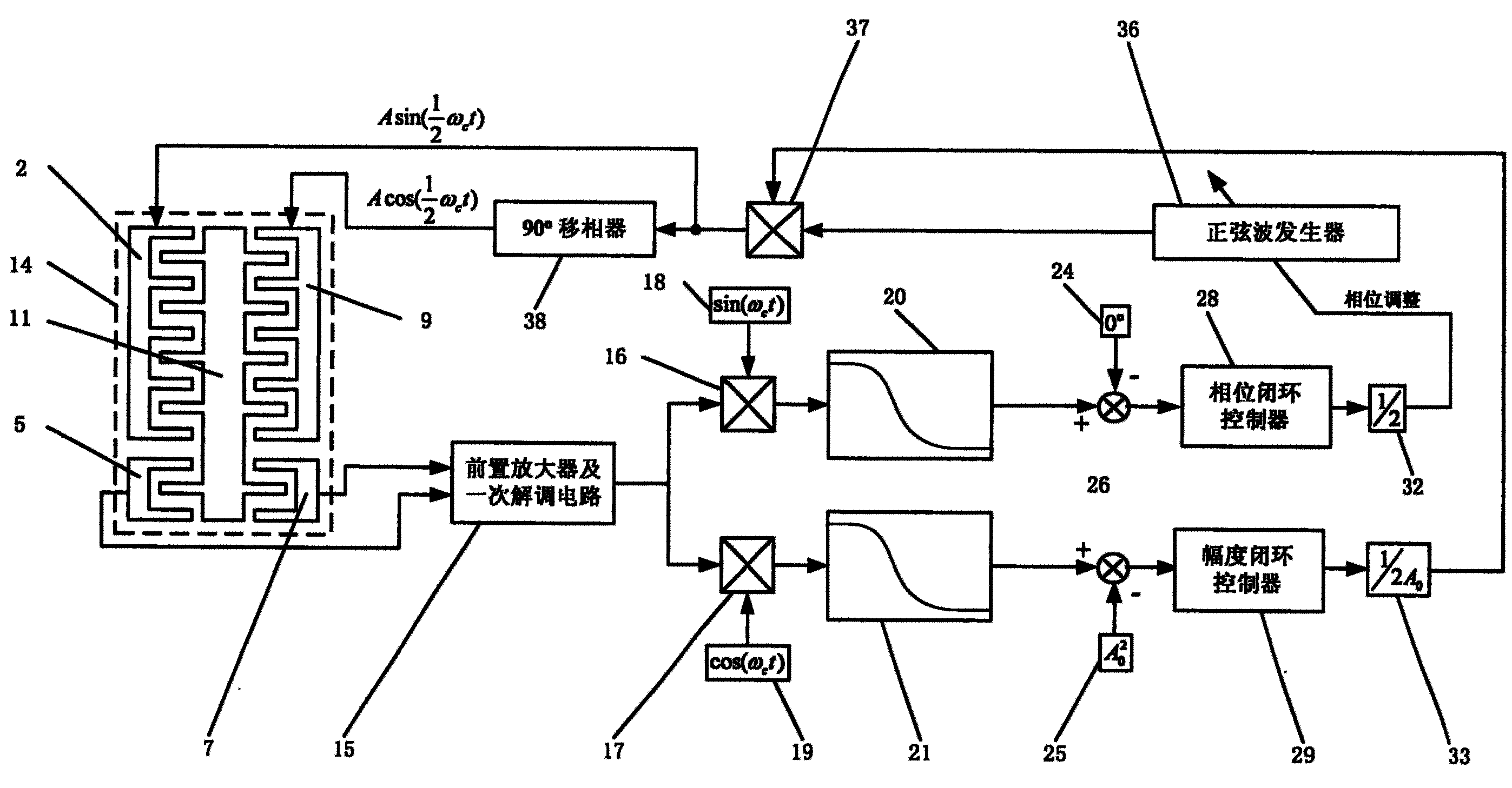
图3是闭环方案原理图。Figure 3 is a schematic diagram of the closed-loop solution.
图中,2.差动梳齿驱动器左侧定子,5.左侧差动检测电极,7.右侧差动检测电极,9.差动梳齿驱动器右侧定子,11.动子,12.余弦驱动电压,13.正弦驱动电压,14.差动梳齿驱动器,15.前置放大器和一次解调电路,16.相位环乘法器,17.幅度环乘法器,18.相位解调参考,19.幅值解调参考,20.相位环低通滤波器,21.幅度环低通滤波器,24.相位闭环设定值,25.幅度闭环设定值,28.相位闭环控制器,29.幅度闭环控制器,32.相位调整因子,33.幅度调整因子,36.正弦波发生器,37.乘法器,38.90°移相器。In the figure, 2. The left stator of the differential comb drive, 5. The left differential detection electrode, 7. The right differential detection electrode, 9. The right stator of the differential comb drive, 11. The mover, 12. Cosine drive voltage, 13. Sine drive voltage, 14. Differential comb driver, 15. Preamplifier and primary demodulation circuit, 16. Phase loop multiplier, 17. Amplitude loop multiplier, 18. Phase demodulation reference, 19. Amplitude Demodulation Reference, 20. Phase Loop Low Pass Filter, 21. Amplitude Loop Low Pass Filter, 24. Phase Closed Loop Setpoint, 25. Amplitude Closed Loop Setpoint, 28. Phase Closed Loop Controller, 29 . Amplitude closed-loop controller, 32. Phase adjustment factor, 33. Amplitude adjustment factor, 36. Sine wave generator, 37. Multiplier, 38. 90° phase shifter.
具体实施方式Detailed ways
下面结合附图来详述一下本发明的原理和具体的实施方式。The principle and specific implementation of the present invention will be described in detail below in conjunction with the accompanying drawings.
本发明所述技术方案的原理在于:在差动梳齿驱动器左、右侧定子上施加一对相差90°无直流偏置的交流电压,其频率为差动梳齿驱动器所需产生的驱动力频率的一半,由于驱动电压和驱动力之间的平方关系,驱动极板上将产生一个带直流分量和倍频交流成分的驱动力,此时利用差动驱动的原理,两个差动驱动极板上的直流分量对消,而剩下的交流成分由于符号相反而合成为所需频率的驱动力,该驱动力可驱动动子按驱动力频率振动。由于驱动电压的频率为驱动力频率的一半,因此驱动信号耦合到器件输出端的电信号其频率是所需器件运动频率的一半,这样在频域上检测信号和耦合信号是分离的,从而达到消除电耦合的效果。另一方面,在噪声影响上,由于电压和力的平方关系,噪声力被调制到驱动电压的频率上,是所需驱动力频率一半处,从而将1/f噪声中低频段转移到该频率附近。The principle of the technical solution of the present invention is that a pair of AC voltages with a difference of 90° and no DC bias are applied to the left and right stators of the differential comb drive, and the frequency thereof is the driving force required by the differential comb drive half of the frequency, due to the square relationship between the driving voltage and the driving force, a driving force with a DC component and a frequency multiplied AC component will be generated on the driving plate. At this time, using the principle of differential drive, two differential drive poles The DC components on the board are cancelled, and the remaining AC components are synthesized into the driving force of the required frequency due to the opposite sign, which can drive the mover to vibrate at the frequency of the driving force. Since the frequency of the driving voltage is half of the frequency of the driving force, the frequency of the electrical signal coupled to the output of the device by the driving signal is half the frequency of the desired device motion, so that the detection signal and the coupling signal are separated in the frequency domain, thereby eliminating The effect of electrical coupling. On the other hand, on the noise effect, due to the square relationship between voltage and force, the noise force is modulated to the frequency of the driving voltage, which is half the frequency of the required driving force, thereby shifting the low frequency band of the 1/f noise to this frequency nearby.
在图1中,一对相差90°、频率相同且电压幅度相等的余弦驱动电压12和正弦驱动电压13分别施加到差动梳齿驱动器左侧定子2和差动梳齿驱动器右侧定子9上,导致定子上的梳齿和动子上的梳齿间产生静电力,该静电力驱动动子11以交流电压频率一倍的频率振动。In Fig. 1, a pair of
现考虑噪声模型,设两电压表达式如下所示:Considering the noise model now, let the two voltage expressions be as follows:
在方程(1)中,A是驱动电压幅度,ωc是动子驱动频率,w1、w2分别为余弦驱动电压和正弦驱动电压上的噪声,ua为余弦驱动电压,ub正弦驱动电压。In equation (1), A is the driving voltage amplitude, ω c is the driving frequency of the mover, w 1 and w 2 are the noise on the cosine driving voltage and sine driving voltage respectively, u a is the cosine driving voltage, u b is the sine driving Voltage.
静电驱动器作为一个非线性能量转换器,是将电压按平方关系转换到驱动力输出,因此差动静电驱动器产生的作用在动子11上的力可表示为:As a non-linear energy converter, the electrostatic driver converts the voltage into the driving force output according to the square relationship, so the force generated by the differential electrostatic driver acting on the
其中ks是与静电驱动器结构相关的常数。where k s is a constant related to the structure of the electrostatic actuator.
在方程(2)中,第一项为主要作用力,第二、三项为噪声被驱动电压调制项,第四、五两项为小量的平方,可忽略,因此作用在动子11上的主要作用力就是第一项。故而加在驱动电极2、9的电压频率与最后作用在动子11上的力频率不同,因而静电力作用在动子11上使其产生的运动频率也与驱动电压频率不同,最终使左侧差动检测电极5和右侧差动检测电极7的输出电信号的频率与驱动电压频率不同,从而可在频域上分离来自驱动电压的电耦合和真正的位移检测输出,达到减小驱动电压电耦合的效果。另一方面,分析第二、三项为驱动电压造成的力噪声影响,驱动电压中的电压噪声一般不是白噪声而是1/f噪声,根据方程(2)可知,该噪声电压通过静电驱动器变成力噪声后,被调制在

采用本发明的驱动方法,可以工作在开环和闭环两种方式下。Adopting the driving method of the present invention, it can work in two modes of open loop and closed loop.
如果用于传感器的力平衡闭环,由于驱动力本身就是作为一种反馈力方式去平衡传感器的受力,因此,半频驱动工作方式为开环方式。具体实施时,直接将一路正弦驱动电压加在差动梳齿驱动器左侧定子2上,另一路与所述正弦驱动电压相位差为90°的余弦驱动电压加在差动梳齿驱动器右侧定子9上,两电压频率和幅度相等,通过产生的静电力使动子运动达到平衡状态。由于本发明的驱动方法具有将噪声移频至

如果用于直接驱动传感器达到稳定的振动,即工作于主动驱动方式,此时应采用闭环工作方式以保证传感器振动的振幅和相位稳定。此时,由于静电驱动器的非线性特性,驱动电压到驱动力为平方非线性关系,因此闭环时需要进行线性化处理,本发明提出了一种简单可行的闭环方案,如图3所示。If it is used to directly drive the sensor to achieve stable vibration, that is, it works in the active drive mode, then a closed-loop working mode should be used to ensure the stability of the vibration amplitude and phase of the sensor. At this time, due to the nonlinear characteristics of the electrostatic driver, the relationship between the driving voltage and the driving force is a square nonlinear relationship, so linearization processing is required when closing the loop. The present invention proposes a simple and feasible closed-loop solution, as shown in FIG. 3 .
在图3中,差动梳齿驱动器14的检测输出由左侧差动检测电极5和右侧差动检测电极7送到前置放大器和一次解调电路15中得到反映动子11振动的信号,经过相位环乘法器16、幅度环乘法器17与相位解调参考18、幅度解调参考19进行相敏解调,并通过相位环低通滤波器20和幅度环低通滤波器21滤波,去除二倍频分量,从而得到动子11振动的相位和幅度。为了稳定动子11的振幅和相位,需要经过幅度和相位两路闭环来进行反馈控制。In Fig. 3, the detection output of the
在幅度闭环中,由于驱动电压和驱动力的关系是平方关系,是一个非线性环节,为了使闭环控制器容易实现,就要进行适当的线性化处理。假设动子11需要驱动到如幅度闭环设定值25所示值A0 2,则在A0 2的小范围内,设检测得到的振幅为A2,则有:In the amplitude closed-loop, because the relationship between the driving voltage and the driving force is a square relationship, it is a nonlinear link. In order to make the closed-loop controller easy to implement, it is necessary to carry out appropriate linearization processing. Assuming that the
采用式(3)的近似线性关系,可得到相应的幅度调整因子33为1/(2A0),从而消除由方程(2)中的平方关系带来的非线性影响,使幅度闭环易于实现。具体实施过程为:将幅度值与幅度闭环设定值25所示值A0 2比较,得到幅度差值;幅度差值经由幅度闭环控制器28进行调整,在本发明中,幅度闭环控制器采用比例积分(PI)控制器,因为其形式简单;然后根据方程(3)将幅度闭环控制器的输出乘以幅度调整因子33所示值1/(2A0)进行修正,通过乘法器37与正弦波发生器36的输出相乘,改变正弦波发生器输出的幅度,达到幅度控制的效果。幅度闭环控制器的传递函数如下所示:Using the approximate linear relationship in equation (3), the corresponding
其中Kp1为比例调节系数,Ki1为积分调节系数,s为拉普拉斯变量。Among them, K p1 is the proportional adjustment coefficient, K i1 is the integral adjustment coefficient, and s is the Laplace variable.
在相位闭环中,从控制电压相位φc到陀螺输出相位φd的关系为线性关系:In the phase closed loop, the relationship from the control voltage phase φ c to the gyro output phase φ d is linear:
由式(5)可得到相位调整因子32为1/2,相位闭环的具体实施过程为:将相位值与相位设定值24比较,得到相位差值;相位差值经由相位闭环控制器29进行调整,在本发明中,相位闭环控制器采用比例积分(PI)控制器;根据方程(5)以相位调整因子32所示值1/2进行修正,得到的相位反馈值去调整正弦波发生器36的相位或者频率,使动子11振动相位发生变化,来保持相位稳定。相位闭环控制器传递函数如下所示:From formula (5), it can be obtained that the
式(6)中参数含义同式(4)。The meanings of the parameters in formula (6) are the same as those in formula (4).
正弦波发生器36的输出经过幅度和相位调整后,即得到一路频率为动子振动频率一半的交流驱动电压。该交流驱动电压经过90°移相器38进行移相处理,得到相差90°且幅度相等的另一路交流驱动电压。After the output of the
将这两路交流驱动电压分别送入静电式差动驱动器的差动梳齿驱动器左侧定子2、差动梳齿驱动器右侧定子9上,驱动动子11振动,使检测电极上的电信号发生变化,从而实现闭环控制。Send these two AC drive voltages to the
Claims (6)
Priority Applications (1)
| Application Number | Priority Date | Filing Date | Title |
|---|---|---|---|
| CNB031573916A CN1299427C (en) | 2003-09-19 | 2003-09-19 | Semi-frequency driving and loop closing method for micro mechanic sensor |
Applications Claiming Priority (1)
| Application Number | Priority Date | Filing Date | Title |
|---|---|---|---|
| CNB031573916A CN1299427C (en) | 2003-09-19 | 2003-09-19 | Semi-frequency driving and loop closing method for micro mechanic sensor |
Publications (2)
| Publication Number | Publication Date |
|---|---|
| CN1490926A CN1490926A (en) | 2004-04-21 |
| CN1299427C true CN1299427C (en) | 2007-02-07 |
Family
ID=34157014
Family Applications (1)
| Application Number | Title | Priority Date | Filing Date |
|---|---|---|---|
| CNB031573916A Expired - Lifetime CN1299427C (en) | 2003-09-19 | 2003-09-19 | Semi-frequency driving and loop closing method for micro mechanic sensor |
Country Status (1)
| Country | Link |
|---|---|
| CN (1) | CN1299427C (en) |
Families Citing this family (3)
| Publication number | Priority date | Publication date | Assignee | Title |
|---|---|---|---|---|
| CN102063057B (en) * | 2010-10-28 | 2012-09-05 | 北京大学 | PID control device for closed loop driving of micro-mechanical resonance type device |
| CN105955247B (en) * | 2016-07-06 | 2018-06-22 | 清华大学 | A kind of dynamic balance closed-loop policy based on decoupling control |
| EP4650795A1 (en) * | 2024-05-14 | 2025-11-19 | Siemens Aktiengesellschaft | Circuit for controlling a field measuring device, method for controlling the field measuring device and field measuring device |
Citations (4)
| Publication number | Priority date | Publication date | Assignee | Title |
|---|---|---|---|---|
| US4553099A (en) * | 1981-03-06 | 1985-11-12 | Matsushita Electric Industrial Co., Ltd. | Electrostatic voltage sensor |
| CN1054485A (en) * | 1989-02-27 | 1991-09-11 | 标准数据控制公司 | Electrostatically driven dual vibrating beam force transducer |
| JPH0814940A (en) * | 1994-06-27 | 1996-01-19 | Yokogawa Electric Corp | Electrostatic drive vibration type sensor circuit |
| US6140737A (en) * | 1999-10-08 | 2000-10-31 | Lucent Technologies Inc. | Apparatus and method for charge neutral micro-machine control |
-
2003
- 2003-09-19 CN CNB031573916A patent/CN1299427C/en not_active Expired - Lifetime
Patent Citations (4)
| Publication number | Priority date | Publication date | Assignee | Title |
|---|---|---|---|---|
| US4553099A (en) * | 1981-03-06 | 1985-11-12 | Matsushita Electric Industrial Co., Ltd. | Electrostatic voltage sensor |
| CN1054485A (en) * | 1989-02-27 | 1991-09-11 | 标准数据控制公司 | Electrostatically driven dual vibrating beam force transducer |
| JPH0814940A (en) * | 1994-06-27 | 1996-01-19 | Yokogawa Electric Corp | Electrostatic drive vibration type sensor circuit |
| US6140737A (en) * | 1999-10-08 | 2000-10-31 | Lucent Technologies Inc. | Apparatus and method for charge neutral micro-machine control |
Also Published As
| Publication number | Publication date |
|---|---|
| CN1490926A (en) | 2004-04-21 |
Similar Documents
| Publication | Publication Date | Title |
|---|---|---|
| CN101454969B (en) | Servo controller | |
| EP2888141B1 (en) | System and method for error correction in angular position sensors | |
| CN1056486C (en) | Method and device for correcting the flux direction of a sensorless, field oriented operating induction machine model flux up to frequency zero | |
| CN103346692B (en) | Frequency domain compensation method for piezoelectric actuator hysteresis nonlinearity in vibration active control | |
| CN111766402A (en) | A kind of tuning control method of micromachined accelerometer | |
| WO2006129612A1 (en) | Electric motor control device | |
| CN109029409B (en) | Parameter amplification method and device in micromechanical gyroscope with tunable gate structure | |
| CN104567849A (en) | Silicon micromechanical line vibrating gyroscope and bandwidth expanding method thereof | |
| CN101145027A (en) | A high-precision magnetic levitation control moment gyro frame servo control system | |
| CN110426025B (en) | A real-time automatic mode matching method for micromachined gyroscope | |
| CN1764824A (en) | Detection circuits, detection method and systems of measuring physical quantities | |
| CN1249565A (en) | Method for controlling and adjusting electric drive device, and apparatus for carrying out said method | |
| WO2012081378A1 (en) | Controlling device for vibration type actuator | |
| CN112821827B (en) | Disturbance suppression system for harmonic reducer of CMG frame system | |
| CN111697874B (en) | Observation Method of Motor Stator Vibration Mode Based on Nonlinear Sliding Mode Observer | |
| CN1490926A (en) | Half-frequency drive and closed-loop method for micromechanical sensors | |
| CN117938008A (en) | Permanent magnet synchronous motor wide voltage range control method and medium based on current lookup table | |
| CN1882889A (en) | Decoupling a harmonic signal from a signal path | |
| CN114499327B (en) | Permanent magnet synchronous motor flux linkage compensation position-sensor-free control method and control system | |
| CN102136830B (en) | Frequency-up drive control method for micromechanical resonant device | |
| CN1228914C (en) | Frequency converter control method and device capable of inhibiting open-loop system oscillation | |
| CN103336523A (en) | Control characteristic testing device and control strategy of ultrasonic motor servocontrol system | |
| CN1945215A (en) | Electromagnetic-piezo-resistance type micro mechanical resonant beam sensor | |
| CN113959424B (en) | Orthogonal real-time correction method, device and related components of a micromechanical gyroscope | |
| CN114826062A (en) | Asynchronous motor indirect magnetic field orientation correction method and correction system thereof |
Legal Events
| Date | Code | Title | Description |
|---|---|---|---|
| C06 | Publication | ||
| PB01 | Publication | ||
| C10 | Entry into substantive examination | ||
| SE01 | Entry into force of request for substantive examination | ||
| C14 | Grant of patent or utility model | ||
| GR01 | Patent grant | ||
| CX01 | Expiry of patent term |
Granted publication date: 20070207 |
|
| CX01 | Expiry of patent term |