CN1313402C - Nut cap assembly and optical fibre cooling method - Google Patents
Nut cap assembly and optical fibre cooling method Download PDFInfo
- Publication number
- CN1313402C CN1313402C CNB021543240A CN02154324A CN1313402C CN 1313402 C CN1313402 C CN 1313402C CN B021543240 A CNB021543240 A CN B021543240A CN 02154324 A CN02154324 A CN 02154324A CN 1313402 C CN1313402 C CN 1313402C
- Authority
- CN
- China
- Prior art keywords
- cap assembly
- heat exchanger
- fiber
- gas
- helium
- Prior art date
- Legal status (The legal status is an assumption and is not a legal conclusion. Google has not performed a legal analysis and makes no representation as to the accuracy of the status listed.)
- Expired - Fee Related
Links
- 238000001816 cooling Methods 0.000 title claims description 27
- 239000013307 optical fiber Substances 0.000 title description 7
- 239000000835 fiber Substances 0.000 claims abstract description 121
- 239000001307 helium Substances 0.000 claims abstract description 76
- 229910052734 helium Inorganic materials 0.000 claims abstract description 76
- SWQJXJOGLNCZEY-UHFFFAOYSA-N helium atom Chemical compound [He] SWQJXJOGLNCZEY-UHFFFAOYSA-N 0.000 claims abstract description 76
- 239000002826 coolant Substances 0.000 claims abstract description 61
- 238000000034 method Methods 0.000 claims abstract description 32
- 239000000112 cooling gas Substances 0.000 claims abstract description 25
- 238000000429 assembly Methods 0.000 claims abstract description 7
- 230000000712 assembly Effects 0.000 claims abstract description 7
- 239000007789 gas Substances 0.000 claims description 112
- 239000012535 impurity Substances 0.000 claims description 16
- 238000007789 sealing Methods 0.000 claims description 15
- CURLTUGMZLYLDI-UHFFFAOYSA-N Carbon dioxide Chemical compound O=C=O CURLTUGMZLYLDI-UHFFFAOYSA-N 0.000 claims description 14
- IJGRMHOSHXDMSA-UHFFFAOYSA-N Atomic nitrogen Chemical compound N#N IJGRMHOSHXDMSA-UHFFFAOYSA-N 0.000 claims description 8
- 238000005192 partition Methods 0.000 claims description 8
- 239000001569 carbon dioxide Substances 0.000 claims description 7
- 229910002092 carbon dioxide Inorganic materials 0.000 claims description 7
- 230000002829 reductive effect Effects 0.000 claims description 7
- 229920006240 drawn fiber Polymers 0.000 claims description 6
- 239000000203 mixture Substances 0.000 claims description 5
- 229910052757 nitrogen Inorganic materials 0.000 claims description 4
- 239000001257 hydrogen Substances 0.000 claims description 3
- 229910052739 hydrogen Inorganic materials 0.000 claims description 3
- UFHFLCQGNIYNRP-UHFFFAOYSA-N Hydrogen Chemical compound [H][H] UFHFLCQGNIYNRP-UHFFFAOYSA-N 0.000 claims 1
- 239000003570 air Substances 0.000 description 29
- 238000001179 sorption measurement Methods 0.000 description 18
- 238000011084 recovery Methods 0.000 description 15
- 238000004064 recycling Methods 0.000 description 10
- 230000009977 dual effect Effects 0.000 description 9
- 239000003463 adsorbent Substances 0.000 description 8
- 238000012681 fiber drawing Methods 0.000 description 8
- 238000004140 cleaning Methods 0.000 description 7
- 239000011521 glass Substances 0.000 description 5
- XLYOFNOQVPJJNP-UHFFFAOYSA-N water Substances O XLYOFNOQVPJJNP-UHFFFAOYSA-N 0.000 description 5
- 238000013461 design Methods 0.000 description 4
- 230000000694 effects Effects 0.000 description 4
- 239000003365 glass fiber Substances 0.000 description 4
- 238000001764 infiltration Methods 0.000 description 4
- 230000008595 infiltration Effects 0.000 description 4
- 238000004519 manufacturing process Methods 0.000 description 4
- 239000005304 optical glass Substances 0.000 description 4
- 238000000746 purification Methods 0.000 description 4
- 238000000926 separation method Methods 0.000 description 4
- 239000010457 zeolite Substances 0.000 description 4
- 229910021536 Zeolite Inorganic materials 0.000 description 3
- 238000010586 diagram Methods 0.000 description 3
- HNPSIPDUKPIQMN-UHFFFAOYSA-N dioxosilane;oxo(oxoalumanyloxy)alumane Chemical compound O=[Si]=O.O=[Al]O[Al]=O HNPSIPDUKPIQMN-UHFFFAOYSA-N 0.000 description 3
- 238000000605 extraction Methods 0.000 description 3
- 239000012528 membrane Substances 0.000 description 3
- 238000012546 transfer Methods 0.000 description 3
- XKRFYHLGVUSROY-UHFFFAOYSA-N Argon Chemical compound [Ar] XKRFYHLGVUSROY-UHFFFAOYSA-N 0.000 description 2
- PNEYBMLMFCGWSK-UHFFFAOYSA-N aluminium oxide Inorganic materials [O-2].[O-2].[O-2].[Al+3].[Al+3] PNEYBMLMFCGWSK-UHFFFAOYSA-N 0.000 description 2
- QVGXLLKOCUKJST-UHFFFAOYSA-N atomic oxygen Chemical compound [O] QVGXLLKOCUKJST-UHFFFAOYSA-N 0.000 description 2
- 238000005452 bending Methods 0.000 description 2
- 238000005253 cladding Methods 0.000 description 2
- 230000003247 decreasing effect Effects 0.000 description 2
- 239000002274 desiccant Substances 0.000 description 2
- 238000001514 detection method Methods 0.000 description 2
- 238000009826 distribution Methods 0.000 description 2
- 238000002474 experimental method Methods 0.000 description 2
- 238000007380 fibre production Methods 0.000 description 2
- 150000002371 helium Chemical class 0.000 description 2
- 125000004435 hydrogen atom Chemical class [H]* 0.000 description 2
- 239000010410 layer Substances 0.000 description 2
- 238000012986 modification Methods 0.000 description 2
- 230000004048 modification Effects 0.000 description 2
- 230000003287 optical effect Effects 0.000 description 2
- 239000001301 oxygen Substances 0.000 description 2
- 229910052760 oxygen Inorganic materials 0.000 description 2
- 239000002245 particle Substances 0.000 description 2
- 238000005086 pumping Methods 0.000 description 2
- 239000002594 sorbent Substances 0.000 description 2
- OKTJSMMVPCPJKN-UHFFFAOYSA-N Carbon Chemical compound [C] OKTJSMMVPCPJKN-UHFFFAOYSA-N 0.000 description 1
- VYPSYNLAJGMNEJ-UHFFFAOYSA-N Silicium dioxide Chemical compound O=[Si]=O VYPSYNLAJGMNEJ-UHFFFAOYSA-N 0.000 description 1
- 230000002411 adverse Effects 0.000 description 1
- 229910052782 aluminium Inorganic materials 0.000 description 1
- XAGFODPZIPBFFR-UHFFFAOYSA-N aluminium Chemical compound [Al] XAGFODPZIPBFFR-UHFFFAOYSA-N 0.000 description 1
- 239000012080 ambient air Substances 0.000 description 1
- 229910052786 argon Inorganic materials 0.000 description 1
- 229910052799 carbon Inorganic materials 0.000 description 1
- 239000003795 chemical substances by application Substances 0.000 description 1
- 238000010276 construction Methods 0.000 description 1
- 125000004122 cyclic group Chemical group 0.000 description 1
- 230000007423 decrease Effects 0.000 description 1
- 238000004821 distillation Methods 0.000 description 1
- 238000011143 downstream manufacturing Methods 0.000 description 1
- 239000011152 fibreglass Substances 0.000 description 1
- 238000010438 heat treatment Methods 0.000 description 1
- 238000009434 installation Methods 0.000 description 1
- 230000000670 limiting effect Effects 0.000 description 1
- 239000000463 material Substances 0.000 description 1
- 229910052751 metal Inorganic materials 0.000 description 1
- 239000002184 metal Substances 0.000 description 1
- 239000002808 molecular sieve Substances 0.000 description 1
- 239000012466 permeate Substances 0.000 description 1
- 239000011241 protective layer Substances 0.000 description 1
- 239000011347 resin Substances 0.000 description 1
- 229920005989 resin Polymers 0.000 description 1
- 239000012260 resinous material Substances 0.000 description 1
- 239000000565 sealant Substances 0.000 description 1
- 239000000741 silica gel Substances 0.000 description 1
- 229910002027 silica gel Inorganic materials 0.000 description 1
- URGAHOPLAPQHLN-UHFFFAOYSA-N sodium aluminosilicate Chemical compound [Na+].[Al+3].[O-][Si]([O-])=O.[O-][Si]([O-])=O URGAHOPLAPQHLN-UHFFFAOYSA-N 0.000 description 1
- 230000000087 stabilizing effect Effects 0.000 description 1
- 229910001220 stainless steel Inorganic materials 0.000 description 1
- 239000010935 stainless steel Substances 0.000 description 1
Images


Classifications
-
- C—CHEMISTRY; METALLURGY
- C03—GLASS; MINERAL OR SLAG WOOL
- C03B—MANUFACTURE, SHAPING, OR SUPPLEMENTARY PROCESSES
- C03B37/00—Manufacture or treatment of flakes, fibres, or filaments from softened glass, minerals, or slags
- C03B37/01—Manufacture of glass fibres or filaments
- C03B37/02—Manufacture of glass fibres or filaments by drawing or extruding, e.g. direct drawing of molten glass from nozzles; Cooling fins therefor
- C03B37/025—Manufacture of glass fibres or filaments by drawing or extruding, e.g. direct drawing of molten glass from nozzles; Cooling fins therefor from reheated softened tubes, rods, fibres or filaments, e.g. drawing fibres from preforms
- C03B37/027—Fibres composed of different sorts of glass, e.g. glass optical fibres
- C03B37/02718—Thermal treatment of the fibre during the drawing process, e.g. cooling
-
- C—CHEMISTRY; METALLURGY
- C03—GLASS; MINERAL OR SLAG WOOL
- C03B—MANUFACTURE, SHAPING, OR SUPPLEMENTARY PROCESSES
- C03B2205/00—Fibre drawing or extruding details
- C03B2205/57—Recovering, recycling or purifying the coolant, e.g. helium
Landscapes
- Engineering & Computer Science (AREA)
- Chemical & Material Sciences (AREA)
- Materials Engineering (AREA)
- Organic Chemistry (AREA)
- General Life Sciences & Earth Sciences (AREA)
- Geochemistry & Mineralogy (AREA)
- Manufacturing & Machinery (AREA)
- Thermal Sciences (AREA)
- Physics & Mathematics (AREA)
- Life Sciences & Earth Sciences (AREA)
- Drying Of Gases (AREA)
- Heat-Exchange Devices With Radiators And Conduit Assemblies (AREA)
- Manufacture, Treatment Of Glass Fibers (AREA)
- Re-Forming, After-Treatment, Cutting And Transporting Of Glass Products (AREA)
- Separation Using Semi-Permeable Membranes (AREA)
- Surface Treatment Of Glass Fibres Or Filaments (AREA)
- Optical Couplings Of Light Guides (AREA)
Abstract
公布了一种用来从一冷却剂腔体管收集冷却气体的盖帽组件。盖帽组件带有连接装置和从其侧壁延伸出的出口装置,它的形状和尺寸一般构造成可分离地安装在冷却气体腔体管的主体上。盖帽组件还应用于用氦气进行冷却的热光纤工艺过程中。
A cap assembly for collecting cooling gas from a coolant cavity tube is disclosed. The cap assembly, with connection means and outlet means extending from a side wall thereof, is generally shaped and sized to be detachably mounted on the main body of the cooling gas chamber tube. Cap assemblies are also used in hot fiber optic processes that are cooled with helium.
Description
技术领域technical field
本发明涉及拉伸纤维的冷却,尤其是涉及使用气态冷却剂的拉伸光学玻璃纤维的冷却。更具体地说,本发明涉及使用盖帽组件来收集从光学玻璃纤维的热交换器抽出的冷却气体,以使从热交换器中损失的冷却剂气体量最少。本发明还涉及使用盖帽组件来向光学玻璃纤维的热交换器供应气体或从其抽出气体。This invention relates to the cooling of drawn fibers, and more particularly to the cooling of drawn optical glass fibers using gaseous coolants. More specifically, the present invention relates to the use of a cap assembly to collect cooling gas drawn from a heat exchanger of optical fiberglass to minimize the amount of coolant gas lost from the heat exchanger. The invention also relates to the use of a cap assembly to supply gas to or extract gas from a heat exchanger of optical glass fibers.
背景技术Background technique
光纤传统上是用玻璃棒或其玻璃中心核心包裹着折射率低于玻璃核心的玻璃包覆层的预制件制成。通过在一炉腔内将玻璃预制件加热到软化温度并从软化的预制件中拉伸出纤维来形成纤维。对纤维快速地进行足够的冷却,以使树脂材料的保护层能覆在拉伸出的纤维的表面。冷却是通过将纤维拉过一个热交换器来实现的,在其中拉伸出的纤维与气态冷却剂接触。Optical fibers are traditionally fabricated from preforms of glass rods or their glass central core surrounded by a glass cladding with a lower refractive index than the glass core. Fibers are formed by heating a glass preform to a softening temperature in a furnace chamber and drawing fibers from the softened preform. The fibers are cooled rapidly enough that a protective layer of resinous material covers the surface of the drawn fibers. Cooling is achieved by drawing the fibers through a heat exchanger, where the drawn fibers come into contact with a gaseous coolant.
气态冷却剂以相对于玻璃纤维穿过热交换器的移动方向横向流动、反向流动、同向流动或者结合这些方式的方向连续地穿过热交换器。气态冷却剂将热量从玻璃纤维传向热交换器的壁,热交换器的壁则由周围的大气和/或在热交换器中的管道中流过的冷却介质(通常为水)来冷却。尽管气态冷却剂也可使用其它的气体或混合物,但一般为氦气。由于氦气传热性能良好且使用安全,故是较佳的冷却剂气体。但是氦气相对其它气体来说是较贵的,所以人们想要将氦气收集起来并进行循环以在热交换器中重复使用。The gaseous coolant passes continuously through the heat exchanger in a direction that flows transversely, counter-flow, co-current, or a combination thereof relative to the direction of movement of the glass fibers through the heat exchanger. The gaseous coolant transfers heat from the glass fibers to the walls of the heat exchanger, which are cooled by the surrounding atmosphere and/or a cooling medium (usually water) flowing through the tubes in the heat exchanger. The gaseous coolant is typically helium, although other gases or mixtures can be used. Helium is the preferred coolant gas due to its good heat transfer properties and its safe use. But helium is expensive compared to other gases, so people want to collect it and recycle it for reuse in heat exchangers.
如果从热交换器中排出的氦气如同在现有的纤维生产过程中所做的那样排到大气中,那么纤维的制造成本就会十分不利地变得更高,尤其是在近30年中纤维的拉伸速度持续增长的情况下。为了降低纤维冷却工序中与氦气的使用相关的纤维制造成本,已提出了用来回收利用氦气的氦气回收利用系统和设备。带有诸如空气和水分之类的杂质的用过的氦气从热交换器中排出,并在再循环回到热交换器的冷却剂气体进给流之前进行净化。If the helium from the heat exchanger was vented to the atmosphere as it is done in the existing fiber production process, the manufacturing cost of the fiber would become quite unfavorably higher, especially in the last 30 years In the case where the stretching speed of the fiber continues to increase. In order to reduce fiber manufacturing costs associated with the use of helium in the fiber cooling process, helium recycling systems and apparatus for recycling helium have been proposed. Spent helium with impurities such as air and moisture is exhausted from the heat exchanger and purified before being recycled back into the heat exchanger's coolant gas feed stream.
但这些氦气回收利用系统存在下列的一个或多个缺点:(1)在收集氦气和施加真空的纤维入口和出口处的周围空气流导致纤维振动;(2)由于回收利用系统缺乏对压力、组成成分以及流速的控制而导致的纤维直径波动,这会对纤维的机械性能和光学质量造成负面影响;(3)由于空气进入到收集气流以及冷却剂(如氦气)从热交换器漏出,使冷却剂(如氦气)的纯度和回收利用率较低。However, these helium recovery systems suffer from one or more of the following disadvantages: (1) the fiber vibrates due to the ambient air flow at the fiber inlet and outlet where the helium is collected and the vacuum is applied; , composition, and control of the flow rate cause fiber diameter fluctuations, which can negatively affect the mechanical properties and optical quality of the fiber; (3) due to air entering the collection airflow and coolant (such as helium) leaking from the heat exchanger , so that the purity and recycling rate of the coolant (such as helium) is low.
通过保证在热交换器内部的冷却气体和周围大气之间的正压力差,就能显著地减少空气的渗入。但这存在一个缺陷,即较贵的氦气就会通过热交换器的纤维入口端开口和/或纤维出口端开口流失到周围环境中。人们已努力在减少通过纤维入口端和出口端开口流出的氦气流出量和空气流入量。例如,对进入热交换器和从热交换器出来的氦气流进行控制以限制空气渗入热交换器中。但是,以大气压力或高于大气压力的压力运转热交换器会造成来自该系统的冷却剂气体的明显损失。人们一直在寻找更为经济的生产光学玻璃纤维的方法。By ensuring a positive pressure differential between the cooling gas inside the heat exchanger and the surrounding atmosphere, air infiltration can be significantly reduced. However, this has the disadvantage that the more expensive helium is lost to the surrounding environment through the fiber inlet opening and/or the fiber outlet opening of the heat exchanger. Efforts have been made to reduce the helium outflow and air inflow through the fiber inlet and outlet openings. For example, the flow of helium into and out of the heat exchanger is controlled to limit air infiltration into the heat exchanger. However, operating the heat exchanger at or above atmospheric pressure can result in a significant loss of coolant gas from the system. People are always looking for more economical methods of producing optical glass fibers.
发明内容Contents of the invention
因此,本发明提供一种新颖的盖帽组件,它能保持高纯度和高回收利用率地收集冷却气体,以降低生产光纤玻璃纤维的成本,并同时解决在纤维生产工艺中空气渗入和冷却剂气体损失的问题。Accordingly, the present invention provides a novel cap assembly that collects cooling gas while maintaining high purity and recycling to reduce the cost of producing optical fiber glass fibers while simultaneously addressing air infiltration and coolant gas in the fiber production process. The problem of loss.
为了实现上述目的,本发明提供一种用来向热交换器装置供应冷却气体和密封气体以及从热交换器装置收集冷却气体的盖帽组件,它包括侧壁、一个在其中心处带有一开口的纤维入口端、一个在其中心处带有一开口的纤维出口端以及在其中心处带有一开口并连接到纤维出口端的连接装置,侧壁带有安装于其中的孔口装置,以使气体可以流过所述侧壁,所述孔口装置包括一从侧壁径向向外延伸的中空孔,其中,所述孔口装置允许气体流入流出所述盖帽组件,并且所述盖帽组件的形状和大小一般构造成可从所述热交换器装置取下。To achieve the above objects, the present invention provides a cap assembly for supplying cooling gas and sealing gas to a heat exchanger unit and collecting cooling gas from the heat exchanger unit, comprising a side wall, a cap assembly with an opening at its center. A fiber inlet end, a fiber outlet end with an opening at its center, and connection means with an opening at its center and connected to the fiber outlet end, with side walls having orifice means fitted therein to allow gas flow Through the side wall, the orifice means includes a hollow hole extending radially outward from the side wall, wherein the orifice means allows gas to flow in and out of the cap assembly, and the shape and size of the cap assembly Typically configured to be removable from the heat exchanger unit.
本发明还提供一种一种在热交换器单元中冷却热拉伸纤维的方法,所述热交换器单元包括单个带有一纤维入口端开口、一个纤维出口端开口、至少一个冷却气体入口的热交换器,一气泵装置以及带有至少一个入口和至少一个出口的盖帽组件,包括以下步骤:The invention also provides a method of cooling hot drawn fibers in a heat exchanger unit comprising a single heat exchanger unit with a fiber inlet end opening, a fiber outlet end opening, at least one cooling gas inlet An exchanger, an air pump unit and a cap assembly with at least one inlet and at least one outlet, comprising the steps of:
1)将纤维拉伸通过所述热交换器;1) drawing the fibers through the heat exchanger;
2)通过至少一个的冷却气体入口将气态冷却剂引入到热交换器中;2) introducing gaseous coolant into the heat exchanger through at least one cooling gas inlet;
3)收集在所述盖帽组件中的冷却气体;以及3) cooling gas collected in the cap assembly; and
4)通过所述泵装置将包含所述气态冷却剂和至少一种气态杂质的用过的气流从盖帽组件抽出。4) Extracting the spent gas stream comprising said gaseous coolant and at least one gaseous impurity from the cap assembly by said pump means.
由此,本发明提供了一种通过使用从热交换器收集冷却气体的盖帽组件来减小光纤冷却系统中的气态冷却剂损失的方法。盖帽组件设计为安装在热交换器的顶部、底部或在其顶部与底部都安装,并且允许纤维穿过盖帽组件(多个盖帽组件)和热交换器。盖帽组件还提供了至少一个孔口装置,它们根据盖帽组件是如何安装在热交换器上和安装在热交换器上的何处能用来供应或抽出冷却和/或密封气体。使用如本发明中所述的装置可以获得很高的冷却剂纯度和回收利用率,且不会对纤维拉伸过程造成任何负面影响,并可以显著地减少或甚至消除空气的进入和氦气的流出。Thus, the present invention provides a method of reducing gaseous coolant loss in fiber optic cooling systems by using a cap assembly that collects cooling gas from a heat exchanger. The cap assembly is designed to be mounted on the top, bottom or both of the heat exchanger and allows fibers to pass through the cap assembly(s) and the heat exchanger. The cap assembly is also provided with at least one orifice means which can be used to supply or extract cooling and/or sealing gas depending on how and where the cap assembly is mounted on the heat exchanger. The use of a device as described in the present invention can achieve very high coolant purity and recycling without any negative impact on the fiber drawing process and can significantly reduce or even eliminate the ingress of air and the ingress of helium. flow out.
在本发明的一个主要的实施例中,本发明包括一种在一热交换器单元中冷却热拉伸纤维的方法,该热交换器单元包括一个纤维入口端开口、一个纤维出口端开口、至少一个冷却气体入口和至少一个冷却气体出口,以及盖帽组件和一气泵装置,并包括以下步骤:将纤维穿过热交换器、通过至少一个的冷却气体入口将气态冷却剂引入到热交换器中以及通过至少一个的气体出口将收集的混有杂质的氦气流抽出盖帽组件,可以净化该混有杂质的氦气流并将其循环回到冷却剂气流中。可选择地,可以将一种诸如氮气、二氧化碳、氢气、氦气(净化好的或从热交换器收集来的)、氩气、干燥空气或者它们的混合气体之类的密封气体引入盖帽组件,从而使渗入的杂质气体和流出热交换器的氦气减到最少。In a principal embodiment of the invention, the invention comprises a method of cooling thermally drawn fibers in a heat exchanger unit comprising a fiber inlet end opening, a fiber outlet end opening, at least a cooling gas inlet and at least one cooling gas outlet, and a cap assembly and an air pump arrangement, and comprising the steps of passing fibers through the heat exchanger, introducing gaseous coolant into the heat exchanger through the at least one cooling gas inlet, and passing the At least one gas outlet draws a collected stream of contaminated helium out of the cap assembly, which stream of contaminated helium can be cleaned and recycled back into the coolant stream. Alternatively, a sealing gas such as nitrogen, carbon dioxide, hydrogen, helium (purified or collected from a heat exchanger), argon, dry air, or a mixture thereof may be introduced into the cap assembly, This minimizes infiltration of impurity gases and helium flow out of the heat exchanger.
附图简述Brief description of the drawings
图1是一个盖帽组件的示意图。Figure 1 is a schematic diagram of a cap assembly.
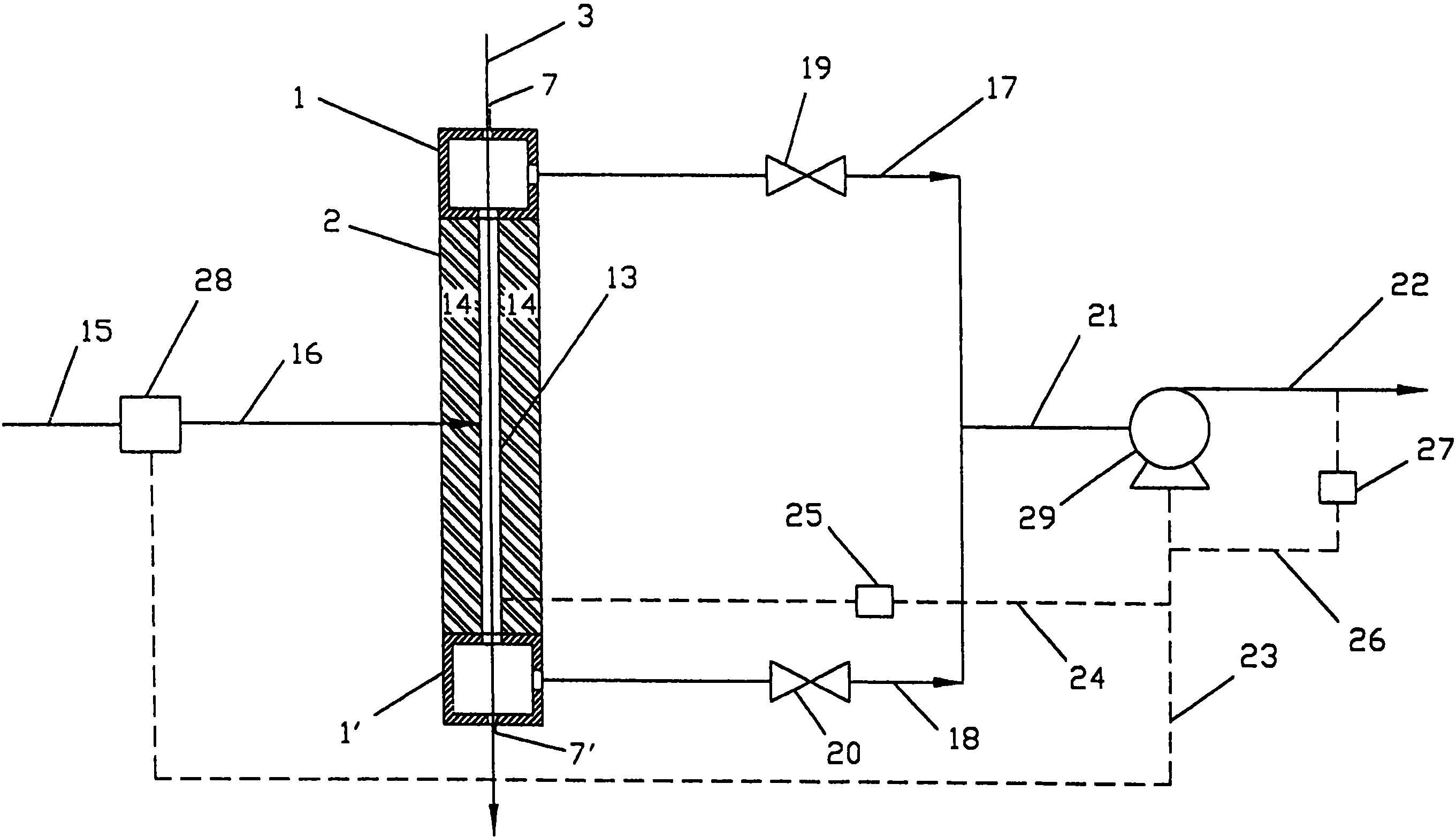
图2是一个实践本发明方法并包括盖帽组件的一个单个单元回收利用系统的示意图。Figure 2 is a schematic illustration of a single unit recycling system for practicing the method of the present invention and including the cap assembly.
图3是一个双腔室盖帽组件的示意图,以及图4是一个多腔室盖帽组件的示意图。Figure 3 is a schematic diagram of a dual chamber cap assembly, and Figure 4 is a schematic diagram of a multi-chamber cap assembly.
图5是氦气回收利用率对收集气流中氦气纯度的点阵图。Figure 5 is a dot plot of helium recovery rate versus helium purity in the collected gas stream.
具体实施方式Detailed ways
本发明提供一种用来收集从光纤热交换器出来的冷却气体的盖帽组件。盖帽的外部形状可以是正方形、矩形、圆柱形或者其它的形状。盖帽组件包括一个在其中心处设有一开口的纤维入口端、一个在其中心处设有一开口的纤维出口端、设有孔口装置以允许气流过其的侧壁以及一个在其中心处带有一开口的连接装置,该连接装置使盖帽组件可与热交换器相连。纤维入口端、纤维出口端以及侧壁形成一个中空的腔室。盖帽的形状和尺寸一般设置为可从热交换器上取下。但是,盖帽组件也可以制成热交换器的一个整体部分。The present invention provides a cap assembly for collecting cooling gas from a fiber optic heat exchanger. The outer shape of the cap can be square, rectangular, cylindrical or other shapes. The cap assembly includes a fiber inlet end having an opening at its center, a fiber outlet end having an opening at its center, side walls having orifice means to allow air flow therethrough, and a fiber outlet end having an opening at its center. Open connection means to allow the cap assembly to be connected to the heat exchanger. The fiber inlet end, the fiber outlet end and the side walls form a hollow chamber. The cap is generally shaped and sized to be removable from the heat exchanger. However, the cap assembly can also be formed as an integral part of the heat exchanger.
盖帽组件可以是一单元或者可以设计成两个或更多个可以铰链连接或不铰链连接的单元。这些部分可用一气缸、机械装置或电气装置来打开或关闭。尽管盖帽组件可以使用任何适合的材料,但它一般是用一种诸如不锈钢或铝之类的金属制成。盖帽组件可设计成内侧壁平行或者从一端向另一端有一定的倾斜度,形成一个锥形的腔室。内侧壁也可以从一端向另一端呈弯曲形。The cap assembly may be one unit or may be designed as two or more units that may or may not be hinged. These parts can be opened or closed with a cylinder, mechanical device or electrical device. The cap assembly is typically made of a metal such as stainless steel or aluminum, although any suitable material can be used. The cap assembly can be designed so that the inner sidewalls are parallel or have a certain inclination from one end to the other to form a tapered cavity. The inner side wall can also be curved from one end to the other.
此外,盖帽组件的纤维入口端可以是平直的或曲线形的,如抛物线形式。在侧壁中的孔口装置允许气体流入或流出盖帽组件的腔室。这些孔口装置可以有螺纹,以使一个通向泵机构的接头可以连接到其上。盖帽组件自身一般安装在热交换器的顶端或底端,或者顶端和底端都安装。盖帽组件通过连接装置来装配到热交换器上。一般来说,会在连接装置、纤维出口端以及热交换器之间涂上某种密封剂,以减少接口处的冷却剂气流失,并保持穿过热交换器的任何真空或气流的完整。连接装置无需置于纤维出口端和热交换器之间,它也可以装在盖帽组件的侧壁和热交换器的侧面上,在这样的情况下,纤维出口端就将直接安装到热交换器上。Additionally, the fiber inlet end of the cap assembly may be straight or curved, such as a parabolic form. An orifice in the side wall allows gas to flow into or out of the chamber of the cap assembly. These orifice means can be threaded so that a connection to the pump mechanism can be attached thereto. The cap assembly itself is typically mounted on the top, bottom, or both top and bottom ends of the heat exchanger. The cap assembly is assembled to the heat exchanger by connecting means. Typically, some kind of sealant is applied between the connection, the fiber outlet end, and the heat exchanger to reduce coolant air loss at the interface and to keep intact any vacuum or airflow through the heat exchanger. The connecting device need not be placed between the fiber outlet port and the heat exchanger, it can also be mounted on the side wall of the cap assembly and the side of the heat exchanger, in which case the fiber outlet port will be mounted directly to the heat exchanger superior.
参照附图可更易理解本发明。图1示出了一个安装在一热交换器2顶部的盖帽组件1。热纤维3穿过盖帽组件和热交换器。图1中所示的盖帽组件1和热交换器2都制作成两个半件。孔口装置8径向穿透标识为4的侧壁。连接装置11将盖帽组件装到热交换器上,它在其中心处带有一个在两个半件相互拼接时形成的开口12或孔,且纤维3穿过它。The invention can be better understood with reference to the accompanying drawings. FIG. 1 shows a
纤维入口端5在它的中心有一个在两个半件相互拼接时形成的开口7,热纤维3从其穿过。纤维出口端6在它的中心有一个在两个半件相互拼接时形成的开口9,纤维3从其穿过。开口一般呈圆形,但也可以是其它的形状。连接装置11和纤维出口端6中的开口一般与热交换器的开口的尺寸和形状相同,而在纤维入口端5处的开口一般小一些。图1剖面A-A所示为一个圆形的盖帽组件,但是盖帽也可以是其它的形状。腔室10由纤维入口端5、侧壁4以及纤维出口端6形成,并且从顶面或侧面看,它可以与盖帽组件的形状不同。The fiber inlet end 5 has in its center an opening 7 formed when the two halves are joined together, through which the
在图2中示出了一个光纤冷却系统,它包括一个热交换器2、一个气流控制器28以及一个气泵装置29。在图2中,盖帽组件1安装在热交换器2的顶部,并且在热交换器2的底部上还装有另一个盖帽组件1′。热交换器2包括一个纤维冷却腔13、纤维入口端、纤维出口端以及套壳14。所示的热交换器带有拉伸过盖帽组件1、腔体13以及盖帽组件1′的玻璃纤维3。该纤维是从一在炉腔内软化了的预制件中拉伸出来的,图中未示出该炉腔,它位于盖帽组件1的上方。冷却剂气体的供应管线15连接到气流控制器28的入口。气流控制器28的出口通过管线16连接到热交换器2。An optical fiber cooling system is shown in FIG. 2 , which includes a
冷却剂气体排出管线17连接到热交换器2顶部上的一个盖帽组件1,同时冷却剂气体排出管线18连接到附着在热交换器2底部的盖帽组件1′。管线17和18分别设有气流控制阀19和20。管线17和18在它们下游的端部连接到管线21,管线21接着连接到泵装置29的吸入端。用过气体的排出管线22将泵装置29的排出连接到一下游的气体净化设备中。热交换器2、气流控制器28以及气泵装置29都是传统的设备,它们的结构和运作方法的细节不构成本发明的一部分。A coolant gas discharge line 17 is connected to a
泵装置可以是任何适于将气体从一个位置移去到另一个位置的泵装置,如一变速鼓风机或连续速度(continuous speed)鼓风机。尽管管线16进入腔体13处所示为一个连到腔体13中心的单管线,但是管线16可位于沿着腔体13长度的任何位置上,或者可使用多根这样的管线来向腔体13供应冷却剂气体。在一个较佳实施例中,供应管线16位于腔体13的纤维出口端处,并且冷却剂气体排出管线17位于腔体13的纤维入口端处,以在与穿过腔体13的纤维流的方向相反的方向提供冷却剂气流。The pumping means may be any pumping means suitable for moving gas from one location to another, such as a variable speed blower or continuous speed blower. Although the place where the line 16 enters the cavity 13 is shown as a single line connected to the center of the cavity 13, the line 16 can be located anywhere along the length of the cavity 13, or multiple such lines can be used to feed the cavity 13. 13 supply coolant gas. In a preferred embodiment, the supply line 16 is located at the fiber outlet end of the cavity 13 and the coolant gas discharge line 17 is located at the fiber inlet end of the cavity 13 to communicate with the fiber flow through the cavity 13. The opposite direction provides coolant flow.
在如图2中所示的结构中,可用阀19和20来关闭管线17或18中的流动,或者可用它们来调整穿过管线17和18的气流的相对速率。泵29的速度控制机构通过气流控制环线23连接到气流控制器28,通过设有压力传感器25的压力控制环线24连到腔体13,并通过设有气态杂质传感器27的管线杂质检测环线26连到管线22。传感器27可以是任何能测量一选择的气态杂质的密度的装置。例如,它可以是一个氧气检测装置。管线22能引导到一个未示出的气体净化系统。气体净化系统可以是任何能够将在该工艺中所用的气态冷却剂从渗入气体热交换器中的气态杂质(如空气、二氧化碳及水蒸气)分离出来的气体净化系统。去除在收集气流中的杂质的适合的气体净化装置包括压力振动吸附(pressure swing adsorption)(PSA)单元、温度振动吸附(temperature swing adsorption)(TSA)单元、可渗透膜分离单元、低温蒸馏设备等等。In a configuration as shown in FIG. 2, valves 19 and 20 may be used to shut off flow in either line 17 or 18, or they may be used to adjust the relative rates of gas flow through lines 17 and 18. The speed control mechanism of the pump 29 is connected to the airflow controller 28 through the airflow control loop 23, connected to the cavity 13 through the pressure control loop 24 provided with the pressure sensor 25, and connected to the pipeline impurity detection loop 26 through the gaseous impurity sensor 27. to line 22. Sensor 27 may be any device capable of measuring the density of a selected gaseous impurity. For example, it could be an oxygen detection device. Line 22 can lead to a gas cleaning system, not shown. The gas cleaning system can be any gas cleaning system capable of separating the gaseous coolant used in the process from the gaseous impurities such as air, carbon dioxide and water vapor that permeate into the gas heat exchanger. Suitable gas purification devices for removing impurities in the collected gas stream include pressure swing adsorption (PSA) units, temperature swing adsorption (TSA) units, permeable membrane separation units, cryogenic distillation equipment, etc. wait.
在较佳的实施例中,气体净化系统是一个PSA设备,当采用适合的吸附剂来使用该设备时,就可以有效和成本较低地从冷却剂气体中去除气态杂质。对工艺进行更为详细的考虑,工艺的第一阶段是从产生穿过热交换器的冷却剂气流开始的。此时,阀19和20中的一个或两者是打开的,且阀的开口调节成所要的程度。接着,就将一个光学玻璃预制件在一放置在盖帽组件1上方的炉腔内加热到它的软化点。当预制件达到其软化点时,它开始流动,形成一根纤维,该纤维被拉伸经过开口7穿过盖帽组件1进入热交换器12的腔体13中,并经过开口7′从盖帽组件1′穿出。In the preferred embodiment, the gas cleaning system is a PSA device which, when used with a suitable adsorbent, provides efficient and inexpensive removal of gaseous impurities from the coolant gas. Considering the process in more detail, the first stage of the process begins with generating a flow of coolant through a heat exchanger. At this point, one or both of valves 19 and 20 are open and the opening of the valves is adjusted to the desired degree. Next, an optical glass preform is heated to its softening point in a furnace chamber placed above the
当纤维穿过热交换器2向下穿行时,它与通过管线16流入腔体13的气态冷却剂接触。气态冷却剂可以是任何不与光纤反应(否则,会有害地影响光纤的质量)的气体。合适的冷却剂气体包括诸如氦气、氢气、氮气、二氧化碳以及这些或其它气体的混合物。冷却剂气体较佳的是含有60%或更大体积含量的氦气,更适宜的是至少90%体积含量的氦气。因为氦气具有良好的传热性能,易于通过传统的分离技术从其它气体中分离,且使用安全,所以相对其它冷却剂气体来说,它是较佳的。As the fiber travels down through the
当氦气通过热交换器2的腔体13时,它冷却了热光纤,因此稳定了纤维并允许它穿过开口7′被拉伸出盖帽组件1′。接着冷却了的光纤就覆上一层树脂并卷绕在一收卷轴上。当管线17、18在鼓风机29的作用下工作时,变热了的或者使用后的氦气就经过盖帽组件1通过管线17和经过盖帽组件1′通过管线18从腔体13排出,并且较佳的是通过管线22送向一个下游的处理系统。As the helium gas passes through the cavity 13 of the
由于氦气的密度低,当穿过腔体13时,它趋向于向上流动。因此,为了使氦气的回收利用率和纯度最优,更希望阀19打开得比阀20要更大一些,以适应在腔体13的顶部内的更多体积的氦气。在一些情况下,会想要完全地关闭阀20,并仅使用管线17来从盖帽组件1中排出用过的气体。Due to the low density of helium, it tends to flow upwards when passing through cavity 13 . Therefore, for optimum helium recovery and purity, it is more desirable that valve 19 be opened somewhat wider than valve 20 to accommodate the greater volume of helium in the top of chamber 13 . In some cases it will be desirable to close valve 20 completely and use line 17 only to vent spent gas from
为了使冷却剂气体的损失最少,泵装置29以一定的速率从腔体13抽出气体,它使至少腔体13中部分的压力在腔体13的冷却剂气体出口处基本保持在大气压力以下,通常在0.5巴与大气压力之间,较佳的是在0.7巴与大气压力之间。用语“基本保持在大气压力以下”指的是尽管整个腔体13的压力可能在一些较短的时段中上升到大于大气压力,但是至少在腔体13的部分中氦气通过腔体13至少90%的时间内,压力保持在大气压力以下。In order to minimize the loss of coolant gas, the pump means 29 draws gas from the cavity 13 at a rate which maintains at least part of the pressure in the cavity 13 substantially below atmospheric pressure at the coolant gas outlet of the cavity 13, Usually between 0.5 bar and atmospheric pressure, preferably between 0.7 bar and atmospheric pressure. The phrase "maintained substantially below atmospheric pressure" means that helium passes through chamber 13 at least in parts of chamber 13 for at least 90 minutes, although the pressure throughout chamber 13 may rise above atmospheric pressure for some relatively short periods of time. % of the time, the pressure remains below atmospheric pressure.
如上所述,气体分离单元可以是任何适合的气体净化设备,但最好是一个PSA系统。它可以包括一单个吸附单元或同相工作的一组吸附单元,或者不同相工作的多个吸附单元或多组吸附单元,任一种都可以。当使用包括一单个吸附单元或者全部同相工作的一组单元的一个系统时,吸附步骤必须周期性地停止以更新吸附剂作用床,而当并列采用多个吸附单元且它们不同相工作时,在一个或多个其它单元进行更新以便放出杂质时,一个或多个单元可以是一个吸附杂质的表面。本发明的吸附系统的运作是循环的。在较佳的吸附方法中,是以净化好的氦气的产量基本连续的方式来重复实现循环。As mentioned above, the gas separation unit can be any suitable gas cleaning equipment, but is preferably a PSA system. It may comprise a single adsorption unit or a group of adsorption units operating in phase, or multiple adsorption units or groups of adsorption units operating in different phases, either. When using a system consisting of a single adsorption unit or a group of units all working in phase, the adsorption step must be stopped periodically to refresh the adsorbent bed, and when multiple adsorption units are used in parallel and they work out of phase, the One or more units may be a surface for absorbing impurities while one or more other units are updated to release impurities. The operation of the adsorption system of the present invention is cyclic. In the preferred adsorption process, the cycle is repeatedly implemented in a substantially continuous manner with the production of purified helium.
在PSA系统中,吸附槽中填满了适合的吸附剂和并为颗粒形式。用于吸附氮气和氧气的适合的吸附剂包括诸如沸石4A、沸石5A及沸石13X之类的沸石或碳分子滤网(sieves)。特别是,用于吸附过程中的吸附剂是要进行选择的,并将部分地由在冷却剂气流中所含的杂质的性能来决定。吸附槽理想的是包含一预净化层,如活化的矾土或硅胶之类的干燥剂,以去除包含在大气中的水蒸气。由于活化的矾土还能用来从空气中去除二氧化碳从而减少或消除被主吸附剂吸附的二氧化碳,故它是较佳的干燥剂。或者,该系统可以包含一单独的空气预净化单元,以在进给气体进入吸附槽之前从其中去除水蒸气和二氧化碳。In a PSA system, the adsorption tank is filled with a suitable adsorbent and is in granular form. Suitable adsorbents for adsorbing nitrogen and oxygen include zeolites such as zeolite 4A, zeolite 5A and zeolite 13X or carbon molecular sieves. In particular, the adsorbent used in the adsorption process is a matter of choice and will be determined in part by the properties of the impurities contained in the coolant gas stream. The adsorption cell ideally contains a pre-purification layer, such as activated alumina or a desiccant such as silica gel, to remove water vapor contained in the atmosphere. Activated alumina is a preferred desiccant because it can also be used to remove carbon dioxide from the air thereby reducing or eliminating carbon dioxide adsorbed by the primary adsorbent. Alternatively, the system may include a separate air pre-cleaning unit to remove water vapor and carbon dioxide from the feed gas before it enters the sorbent.
PSA过程运行所处的温度和压力是需要进行选择而不是决定性的事宜。一般来说,吸附过程可以在约-50至约100℃范围的温度下进行,但一般在约0至约40℃范围的温度下进行。一般来说,吸附是在1巴或之上的压力下进行的。吸附步骤进行的最小的压力较佳的是约2巴,并更佳的是约5巴。压力的上限值是由经济方面的问题和吸附系统的局限性来决定的,并且它一般理想的是约50巴,较佳的是约20巴,并且最佳的是约15巴。吸附剂进行更新的压力也同样是需要进行选择的,并且最小的压力取决于是否使用真空设备来从这些槽中抽出吸附的气体。在这些槽的吸附剂更新过程中的压力下限值一般可以低至50毫巴,但较佳的是不低于约150毫巴,并且最佳的是不低于约200毫巴。吸附剂更新可以在高至5巴的压力下进行,但较佳的是在不高于约2巴的压力下进行,并且最佳的是在不大于1巴。The temperature and pressure at which the PSA process operates is a matter of choice, not conclusive. Generally, the adsorption process can be carried out at a temperature ranging from about -50°C to about 100°C, but generally at a temperature ranging from about 0°C to about 40°C. Generally, adsorption is carried out at a pressure of 1 bar or above. The minimum pressure at which the adsorption step is carried out is preferably about 2 bar, and more preferably about 5 bar. The upper pressure limit is determined by economical considerations and limitations of the adsorption system, and is generally ideally about 50 bar, preferably about 20 bar, and most preferably about 15 bar. The pressure at which the adsorbent is refreshed is also selective, and the minimum pressure depends on whether vacuum equipment is used to draw the adsorbed gas from the tanks. The lower pressure limit during adsorbent refresh of these cells can generally be as low as 50 mbar, but is preferably not lower than about 150 mbar, and most preferably not lower than about 200 mbar. Sorbent refreshment can be carried out at pressures up to 5 bar, but is preferably carried out at a pressure not higher than about 2 bar, and most preferably not greater than 1 bar.
在图3中示出了盖帽组件的一个可替代实施例。盖帽组件1所示为安装在一热交换器2的顶部,其中热纤维3穿过盖帽组件1和热交换器2两者。孔口装置35和36径向延伸过标识为31的侧壁。连接装置42将盖帽连接到热交换器2上。纤维入口端32在其中心处有一个热纤维3穿过的开口34。纤维出口端33在其中心处有一个热纤维3穿过的开口37。在该实施例中,盖帽组件由图3中所示的分隔壁39分隔成两个各别的腔室40和41。分隔壁39将盖帽组件分隔成两个大小相同的腔室,或者分隔壁39也可以设置在形成两个不同大小的腔室的位置上。在图1和3所示的实施例中都应予注意的是,单腔室或双腔室的盖帽组件都可以具有一个或多个可通过其抽出或供给气体的孔口装置。例如,图3中的孔口装置35可以用作密封气体的供给孔口装置,而孔口装置36则可用作抽出冷却气体的孔口装置。或者,孔口装置35也被封住,而孔口装置36可被用来从盖帽装置抽出气体。An alternative embodiment of a cap assembly is shown in FIG. 3 . The
尽管任何气体都可以用作在热交换器顶部上的盖帽组件的密封气体,但较佳的是取出一部分的收集来的气体并将其用作密封气体。通过这样做,就可在收集起来的气流中获得更高的冷却剂气体密度。盖帽组件的腔室和分隔壁可以是分别制作并堆叠在一起的,这不仅使制造和安装更容易,而且使冷却装置的变动更灵活。可以根据冷却装置的几何形状和操作条件来设计各个腔室和分隔壁开口的尺寸。Although any gas can be used as the sealing gas for the cap assembly on top of the heat exchanger, it is preferred to take a portion of the collected gas and use it as the sealing gas. By doing so, a higher coolant gas density can be achieved in the collected gas stream. The chamber and the partition wall of the cap assembly can be made separately and stacked together, which not only makes the manufacture and installation easier, but also makes the cooling device more flexible. The dimensions of the individual chambers and partition wall openings can be designed according to the geometry and operating conditions of the cooling device.
当盖帽组件用在热交换器的底部来收集冷却气体时,盖帽组件将以与图3中所示的位置颠倒的位置来附着在冷却装置上,并且通道36用作气体抽出孔口装置,通道35用作密封气体供应孔口装置。或者,在冷却气体从底部供入的情况下,盖帽组件可以用作进给腔室,其中35和36都用作供应孔口装置。冷却气体可以会通过孔口装置36被引入盖帽组件,并且密封气体会通过孔口装置35被引入盖帽组件。When the cap assembly is used at the bottom of the heat exchanger to collect cooling gas, the cap assembly will be attached to the cooling device in a position reversed from that shown in Figure 3, and the
现在请参见图4,它代表一个多腔室的盖帽,其中存在着两个以上的腔室。图4示出了两个孔口装置60和61,但是其中可以少到仅有一个孔口装置或者每个腔室都可以有它们自己的孔口装置。这个盖帽组件标识为44,并且所示为安装在热交换器2的顶部,或者它可以与图4中所示的位置颠倒的位置安装在热交换器2的底部。图中示出了热纤维3穿过盖帽组件和热交换器2。孔口装置60和61径向延伸穿透标识为45的侧壁。连接装置68将盖帽组件连接到热交换器2上。同样,纤维入口端46在其中心处有一个热纤维3穿过的开口53。纤维出口端52在其中心处有一个热纤维3穿过的开口59。在多腔室盖帽组件中,多个腔室62-67由分隔壁47-51来形成。各个腔室可以有它们自己的孔口装置(例如60和61)。用来形成腔室的分隔壁在它们的中心处各有一个与开口53相似开口(54-58),以使纤维可以穿过它们。图4示出了一个带有若干腔室的盖帽组件,但可以增加或减少腔室的数量。Referring now to Figure 4, it represents a multi-chambered cap in which there are more than two chambers. Figure 4 shows two
如同在单腔室盖帽组件和双腔室盖帽组件中一样,孔口装置60和61可以用作气体入口或出口。因此,在多腔室盖帽组件中,当盖帽组件安装在热交换器组件的底部时,孔口装置60和61可被用来向盖帽组件供应气体。当盖帽组件安装在热交换器组件的顶部时,孔口装置60和61可以一个用来供应密封气体、另一个用来从多腔室盖帽组件抽出冷却气体。同样,也可以在盖帽组件中采用一个或多个入口/出口装置(如60和61)。As in the single and dual chamber cap assemblies, the
应予注意的是,尽管在图1、3及4中所示的盖帽组件中形成腔室的侧壁、分隔壁、纤维入口端以及纤维出口端的是平直和/或相互平行的,但是它们也可以是任何形状和方位,以便于气流入盖帽组件并消除对纤维拉伸过程的负面影响或使其最小。It should be noted that although the side walls, the partition wall, the fiber inlet end and the fiber outlet end of the chamber are formed in the cap assembly shown in FIGS. 1, 3 and 4 are straight and/or parallel to each other, they It can also be of any shape and orientation to facilitate airflow into the cap assembly and eliminate or minimize negative effects on the fiber drawing process.
下文将结合盖帽组件的设计和纤维拉伸/冷却工艺的操作,对本发明中叙述的盖帽组件的一些关键特征和优点进行描述。应予强调的是,组件的几何形状和操作对于回收利用系统和纤维拉伸过程是关键的。例如,描述一纤维冷却热交换器,其中氦气从底部供向热交换器和用过的气体从顶部排出。Some key features and advantages of the cap assembly described in the present invention will be described below in connection with the design of the cap assembly and the operation of the fiber drawing/cooling process. It should be emphasized that the geometry and operation of the components are critical to the recycling system and fiber drawing process. For example, a fiber cooled heat exchanger is described wherein helium gas is supplied to the heat exchanger from the bottom and spent gas is exhausted from the top.
与不使用任何冷却剂回收利用设备的一热交换器相比,该组件提供了改变从热交换器来的已用冷却剂气体方向的装置。用过的冷却剂气体不是从顶部的纤维入口向上排出,而是能改变方向以在垂直于纤维的径向方向上流动。排出热交换器的气体流动方向的改变防止了在周围大气中的颗粒被吹入位于热交换器上方的炉腔内,这些颗粒会污染预制件和正在拉伸的纤维。This assembly provides means to redirect the spent coolant gas from the heat exchanger as compared to a heat exchanger without any coolant recovery equipment. Instead of exiting upwards from the fiber inlet at the top, the spent coolant gas can be redirected to flow in a radial direction perpendicular to the fibers. The redirection of the flow of gas exiting the heat exchanger prevents particles in the surrounding atmosphere from being blown into the furnace cavity above the heat exchanger, which particles would contaminate the preform and the fiber being drawn.
在氦气的回收利用系统中实施将氦气直接从热交换器抽出。在那些情况下,用过的气体从之取出的间隔相对较窄,尤其是对带有小直径冷却腔体管的热交换器来说。这样,为了抽出用过的气流,通常就需要更强的真空,否则用过气体的相当一部分将会从纤维入口损失掉。更强的真空往往会干扰在热交换器冷却腔体管中的气流动图案以及压力分布,这会造成对拉伸过程的干扰和冷却效率的降低(或氦气冷却剂气体用量的增加)。如果使用了本发明所述的组件,在该组件中的压降与在热交换器内氦气通道中的压降相比是很小的。因此,就能够以一个相对较低的真空收集用过的氦气,而不会对纤维拉伸过程产生干扰。为了减少从纤维入口吸入的空气,可以使用一个双腔室或多腔室的组件,其中,收集的气体或其它气体的一部分可以作为密封气体引入到例如一双腔室组件的上腔室中。根据冷却剂的进给流和施加在用过气体收集腔上的真空来对密封气流进行调整。作为选择,也可以在抽出和密封气体之间设置一个或多个腔室,以使该组件中的流动图案和压力分布达到最佳。组件几何形状和抽出腔室的孔口装置的取向设计可以使组件内气流对于纤维的影响(如产生纤维振动)最小。例如,在该组件内可以放置气体分配器、导风板或者多孔管。In the recovery and utilization system of helium, the helium is directly extracted from the heat exchanger. In those cases, the intervals from which the spent gas is withdrawn are relatively narrow, especially for heat exchangers with small diameter cooling chamber tubes. Thus, in order to evacuate the spent gas stream, a stronger vacuum is usually required, otherwise a significant portion of the used gas will be lost from the fiber inlet. A stronger vacuum tends to disturb the airflow pattern and pressure distribution in the cooling cavity tubes of the heat exchanger, which can cause disturbances in the stretching process and reduced cooling efficiency (or increased helium coolant gas usage). If the assembly according to the invention is used, the pressure drop in the assembly is small compared to the pressure drop in the helium channel in the heat exchanger. As a result, spent helium can be collected at a relatively low vacuum without disturbing the fiber drawing process. To reduce the intake of air from the fiber inlet, a dual or multi-chamber assembly can be used, wherein a portion of the collected gas or other gases can be introduced as sealing gas into, for example, the upper chamber of a dual-chamber assembly. Seal gas flow is adjusted based on coolant feed flow and vacuum applied to the spent gas collection chamber. Optionally, one or more chambers may be provided between the extraction and sealing gas to optimize the flow pattern and pressure distribution in the assembly. The geometry of the module and the orientation of the orifice means of the extraction chamber are designed to minimize the effects of air flow in the module on the fibers (eg, fiber vibration). For example, gas distributors, wind deflectors or perforated pipes can be placed within the assembly.
在许多商品化的热交换器中,通过一单腔室进给组件从底部进给冷却剂。通常在进给组件的底部附着一膜片(iris)以限值冷却剂从进给腔体流出。膜片开口的直径是相当小的(通常在1至5毫米之间),在膜片处的气流速可以达到每分钟50米或更高,这取决于进给流的速率、冷却腔体管的直径和冷却腔体管的长度,以及膜片直径。通过膜片的高气体速率可能使纤维振动,这会致使纤维断裂并影响纤维的质量。In many commercial heat exchangers, the coolant is fed from the bottom through a single chamber feed assembly. Usually a diaphragm (iris) is attached to the bottom of the feed assembly to limit the flow of coolant from the feed cavity. The diameter of the diaphragm opening is quite small (usually between 1 and 5 mm), and the gas flow rate at the diaphragm can reach 50 meters per minute or more, depending on the feed flow rate, cooling chamber tube The diameter and length of the cooling chamber tube, as well as the diaphragm diameter. The high gas velocity through the diaphragm may vibrate the fiber, which can cause fiber breakage and affect the quality of the fiber.
另一个与膜片设计相关的问题是从底部损失的冷却剂的百分比随着进给流的降低而增加,并且不能方便地进行调整以变化流速。通过在热交换器的底部使用一双腔室或多腔室的组件,并且同时将冷却剂供应到上腔室、将密封气体供应到例如一双腔室组件的底部腔室,就可以大大地减少冷却剂气体经过纤维出口的损失,并且也可以根据进给流来对密封气流进行调整。此外,在底部腔室处的纤维出口的开口尺寸可以比曾要使用的膜片的开口大,但不会引起冷却剂从底部流失。通过这样做,就减小了在纤维出口处的线速度,并因而也大大地减少了因高流速而导致纤维振动的可能性。Another problem associated with the diaphragm design is that the percentage of coolant lost from the bottom increases with decreasing feed flow and cannot be easily adjusted to vary the flow rate. Cooling can be greatly reduced by using a dual or multi-chamber assembly at the bottom of the heat exchanger and simultaneously supplying coolant to the upper chamber and seal gas to, for example, the bottom chamber of a dual-chamber assembly The loss of agent gas through the fiber exit and the sealing gas flow can also be adjusted according to the feed flow. Furthermore, the opening size of the fiber outlet at the bottom chamber can be larger than the opening of the membrane would have been used without causing loss of coolant from the bottom. By doing so, the linear velocity at the exit of the fiber is reduced, and thus the possibility of fiber vibration due to high flow rates is greatly reduced.
如果从热交换器或单腔室氦气收集组件直接收集氦气,那么就无法独立地改变氦气的回收利用率和氦气的纯度。一般来说,在拉伸腔室中的真空压力应保持在一个相对不变的水平,以使对纤维拉伸过程的干扰最小。可对密封气流的速度进行调整使它能保持收集气流的冷却剂纯度。If the helium is collected directly from a heat exchanger or a single-chamber helium collection assembly, then the helium recovery and helium purity cannot be varied independently. In general, the vacuum pressure in the drawing chamber should be maintained at a relatively constant level to minimize disturbance to the fiber drawing process. The velocity of the seal airflow can be adjusted so that it maintains the coolant purity of the collected airflow.
下面将通过以下的例子来示范本发明。应将这些例子认为是本发明的示范例,而不是必需的限制。The present invention will be demonstrated by the following examples. These examples should be considered exemplary of the invention, and not necessarily limiting.
示例example
例1:example 1:
单腔室和双腔室盖帽组件的所收集氦气的纯度和空气进入示于表1。当纤维进入盖帽组件的流道长度从0.25英寸增加到1英寸时,氦气的纯度从46%增长到53%。与此同时,由于流道的额外长度对空气进入施加了更多的阻力,所以空气进入流速从16.9SLPM降至15.7SLPM。The purity of the collected helium and air ingress are shown in Table 1 for the single-chamber and dual-chamber cap assemblies. The purity of the helium gas increased from 46% to 53% when the length of the flow path of the fiber into the cap assembly was increased from 0.25 inches to 1 inch. At the same time, the air inlet flow rate dropped from 16.9 SLPM to 15.7 SLPM due to the extra length of the runners applying more resistance to the air entry.
表1.在所收集的冷却剂气流中的氦气纯度和空气进入
如表1中所示,一个双腔室的盖帽组件设计可以得到比单腔室盖帽组件设计所获得的氦气纯度更高的氦气纯度。通过减小收集腔室的体积并增加缓冲腔室的体积,氦气的密度就从65%增加到69%,并且空气进入也从8.1SLPM降至6.1SLPM。在热交换器顶部和底部的各双腔室盖帽组件都采用密封气体可以减少冷却剂损失和空气的进入,并进一步改善系统的效率。As shown in Table 1, a dual-chamber cap assembly design can yield higher helium purity than a single-chamber cap assembly design. By reducing the volume of the collection chamber and increasing the volume of the buffer chamber, the density of helium is increased from 65% to 69%, and the air intake is also reduced from 8.1 SLPM to 6.1 SLPM. Each dual chamber cap assembly at the top and bottom of the heat exchanger uses seal gas to reduce coolant loss and air ingress and further improve system efficiency.
例2:Example 2:
在一个15米高的光纤拉伸塔的一热交换器上进行氦气回收利用收集实验。在热交换器(或冷却装置)的底部固定有一个双腔室盖帽组件。将氦气用作为冷却剂气体,该冷却剂气体进给入在热交换器底部的一盖帽组件中。热交换器的内流道直径为10毫米,高度为2米。光纤所穿过的盖帽组件开口的直径为3至5毫米。光纤的拉伸速度从每秒3米变化至每秒20米。根据纤维拉伸速度进行变化的氦气进给流速在每分钟0至100升之间变化。光纤进入盖帽组件的上腔室被用作氦气进给腔,纤维离开盖帽组件的下腔室被用作密封气体腔。将干燥的空气用作密封气体。在热交换器的顶部使用了另一个盖帽组件。对用作冷却剂收集盖帽组件的单腔室和双腔室盖帽组件都进行了实验。在热交换器顶部使用双腔室盖帽组件的情况下,用过的冷却剂从与在纤维出口处的腔室连接的出口装置抽出,并且同时将密封气体(它来自收集的氦气流)在纤维入口端处进给入腔室。对进给到顶部和底部盖帽组件的密封气体进行调整,以使氦气的回收利用率最高。Helium recovery and utilization collection experiments were carried out on a heat exchanger of a 15-meter-high optical fiber drawing tower. At the bottom of the heat exchanger (or cooling unit) is affixed a dual chamber cap assembly. Helium was used as the coolant gas which was fed into a cap assembly at the bottom of the heat exchanger. The inner flow channel of the heat exchanger has a diameter of 10 mm and a height of 2 meters. The opening of the cap assembly through which the optical fiber passes has a diameter of 3 to 5 mm. The drawing speed of the fiber varies from 3 meters per second to 20 meters per second. The helium feed flow rate was varied between 0 and 100 liters per minute, which varied according to the fiber draw speed. The upper chamber where the fiber enters the cap assembly is used as the helium feed chamber and the lower chamber where the fiber exits the cap assembly is used as the seal gas chamber. Use dry air as the sealing gas. Another cap assembly is used on top of the heat exchanger. Experiments were conducted with both single chamber and dual chamber cap assemblies used as coolant collection cap assemblies. In the case of using a dual chamber cap assembly at the top of the heat exchanger, the spent coolant is drawn from an outlet device connected to the chamber at the fiber outlet and at the same time sealing gas (which comes from the collected helium flow) is drawn over the fiber The inlet port feeds into the chamber. The seal gas feed to the top and bottom cap assemblies is adjusted to maximize helium recovery.
当向上气流的摩擦力大于拉伸所产生的纤维拉力时,在热交换器冷却腔体管和盖帽组件中的湍流可能会引起纤维的小幅振动。纤维的振动会造成纤维弯曲或扭转,弯出或扭转会使光纤变细。当振动变得过大时,纤维会撞击在热交换器的壁上,导致其切断或断裂。在0至14英寸水标(IWG)的较宽范围的真空度(在真空泵的吸入侧进行测量)下未观测到振动。Turbulent flow in the heat exchanger cooling chamber tube and cap assembly may cause small vibrations in the fibers when the friction of the upward airflow is greater than the fiber pull produced by stretching. Vibration of the fiber causes bending or twisting of the fiber, and bending out or twisting makes the fiber thinner. When the vibration becomes excessive, the fibers can strike against the walls of the heat exchanger, causing it to shear or break. Vibration was not observed over a wide range of vacuum levels (measured on the suction side of the vacuum pump) from 0 to 14 inches water gauge (IWG).
在纤维拉伸操作中,根据覆层后的纤维的外径对氦气的流速进行调整。覆层纤维直径比特定值小就意味着需要更高的冷却能力,因而就要相应地加大氦气的流速。During the fiber drawing operation, the helium flow rate was adjusted according to the outer diameter of the coated fiber. A cladding fiber diameter smaller than a certain value means that higher cooling capacity is required, so the flow rate of helium must be increased accordingly.
通过测量使用和不使用氦气回收利用系统的覆层纤维直径来研究氦气收集在冷却效率方面的效果。The effect of helium collection on cooling efficiency was investigated by measuring the diameter of clad fibers with and without a helium recovery system.
纤维直径的测得值显示,氦气收集系统不会降低光纤热交换器的冷却效率。因此,氦气需求量不会因为添加了氦气回收利用系统而增大。The measured values of the fiber diameter show that the helium collection system does not reduce the cooling efficiency of the fiber optic heat exchanger. Therefore, the demand for helium will not increase due to the addition of a helium recycling system.
图5示出了在不同的操作条件下(亦即真空度、进给流速、密封气体流速以及纤维拉伸速度)的收集气流的氦气纯度和收集回收利用率。收集回收利用率是收集装置所收集的氦气量为进入热交换器内的氦气量的百分比。Figure 5 shows the helium purity and collection recovery of the collection gas stream at different operating conditions (ie, vacuum level, feed flow rate, sealing gas flow rate, and fiber draw speed). The collection recovery rate is the percentage of the amount of helium collected by the collection device to the amount of helium entering the heat exchanger.
如可从图中所见,获得了高达80%至90%的氦气回收利用率和97%至99%的收集氦气流的纯度。一般来说,在较低的氦气纯度时测得的氦气回收利用率更高。在所给例子中的高氦气纯度显示了不再进行净化而直接循环氦气的可能性,这极大地减少了氦气回收利用系统的投资成本。但是,使用诸如PSA、TSA、渗透膜之类的净化过程将同时提高氦气的回收利用率和纯度。应根据氦气流速值、拉伸塔和热交换器的类型以及纤维的拉伸操作来决定所选择的系统。As can be seen from the figure, a helium recovery rate as high as 80% to 90% and a purity of the collected helium stream of 97% to 99% are obtained. In general, higher helium recovery efficiencies are measured at lower helium purity. The high helium purity in the given example shows the possibility of direct recycling of the helium without purification, which greatly reduces the investment costs of the helium recycling system. However, the use of purification processes such as PSA, TSA, permeable membranes will improve both helium recovery and purity. The system chosen should be determined by the value of the helium flow rate, the type of draw tower and heat exchanger, and the drawing operation of the fiber.
当真空度提高时,由于更多的杂质被吸入收集气流中,所以收集气体的纯度降低。在另一方面,当真空度提高时,氦气回收利用率上升,因而减少了氦气损失量。As the vacuum increases, the purity of the collected gas decreases as more impurities are drawn into the collected gas stream. On the other hand, when the vacuum degree is increased, the recovery rate of helium gas is increased, thereby reducing the amount of helium gas loss.
尽管本发明是对其特殊的实施例进行描述的,但显然,对那些熟悉本技术领域的人们来说,本发明的种种其它形式和修改变型是显而易见的。在本发明文件中的所附权利要求书一般应被认为覆盖了在本发明真正构思范围内的所有这样明显的变化形式和修改变型。While this invention has been described in terms of particular embodiments thereof, it is evident that various other forms and modifications of this invention will be apparent to those skilled in the art. The appended claims in this specification should generally be considered to cover all such obvious changes and modifications which are within the true concept of the invention.
Claims (16)
Applications Claiming Priority (2)
| Application Number | Priority Date | Filing Date | Title |
|---|---|---|---|
| US09/998,288 | 2001-11-30 | ||
| US09/998,288 US6789400B2 (en) | 2001-11-30 | 2001-11-30 | Cap assembly and optical fiber cooling process |
Publications (2)
| Publication Number | Publication Date |
|---|---|
| CN1421410A CN1421410A (en) | 2003-06-04 |
| CN1313402C true CN1313402C (en) | 2007-05-02 |
Family
ID=25545007
Family Applications (1)
| Application Number | Title | Priority Date | Filing Date |
|---|---|---|---|
| CNB021543240A Expired - Fee Related CN1313402C (en) | 2001-11-30 | 2002-11-29 | Nut cap assembly and optical fibre cooling method |
Country Status (8)
| Country | Link |
|---|---|
| US (2) | US6789400B2 (en) |
| EP (1) | EP1316535B1 (en) |
| JP (1) | JP2003192375A (en) |
| CN (1) | CN1313402C (en) |
| AT (1) | ATE412618T1 (en) |
| AU (1) | AU2002301395B2 (en) |
| BR (1) | BR0204905A (en) |
| DE (1) | DE60229609D1 (en) |
Cited By (1)
| Publication number | Priority date | Publication date | Assignee | Title |
|---|---|---|---|---|
| CN101392278B (en) * | 2008-06-11 | 2011-07-20 | 济南大华广济畜牧发展有限公司 | Method for preparing D-pantolactone by microbe mixed fermentation method |
Families Citing this family (19)
| Publication number | Priority date | Publication date | Assignee | Title |
|---|---|---|---|---|
| KR100459570B1 (en) * | 2002-01-19 | 2004-12-04 | 삼성전자주식회사 | Cooling device with sealing cap for high-speed drawing in fiber drawing process |
| US20030205066A1 (en) * | 2002-03-25 | 2003-11-06 | Ghani M. Usman | Method and apparatus for efficient cooling of optical fiber during its manufacture |
| US20030200772A1 (en) * | 2002-04-30 | 2003-10-30 | Foster John D. | Methods and apparatus for forming optical fiber |
| US6701728B1 (en) | 2002-08-28 | 2004-03-09 | The Boc Group, Inc. | Apparatus and method for recovery and recycle of optical fiber coolant gas |
| US20040194513A1 (en) * | 2003-04-04 | 2004-10-07 | Giacobbe Frederick W | Fiber coolant system including improved gas seals |
| US20070113589A1 (en) * | 2005-11-18 | 2007-05-24 | Paganessi Joseph E | Gas Control Device and Corresponding Method for Recovering Coolant Gases in a Fiber Coolant System |
| CN101143762B (en) * | 2006-09-13 | 2012-01-25 | 乔治洛德方法研究和开发液化空气有限公司 | Gas control device and corresponding method for recovering coolant gases in a fiber coolant system |
| JP5323530B2 (en) * | 2009-02-23 | 2013-10-23 | 古河電気工業株式会社 | Optical fiber manufacturing method |
| US8973408B2 (en) * | 2010-05-27 | 2015-03-10 | Corning Incorporated | Method for producing optical fiber using linear non-contact fiber centering |
| CN106477875A (en) * | 2015-08-27 | 2017-03-08 | 北京回能环保科技有限公司 | A kind of fiber drawing furnace helium catcher |
| US10308544B2 (en) | 2015-10-13 | 2019-06-04 | Corning Incorporated | Gas reclamation system for optical fiber production |
| CN105293456A (en) * | 2015-11-24 | 2016-02-03 | 安徽万瑞冷电科技有限公司 | Efficient helium gas recovery apparatus |
| EP3282023A1 (en) * | 2016-08-11 | 2018-02-14 | Linde Aktiengesellschaft | Cooling device and method for cooling continuous elements |
| US10962727B2 (en) * | 2019-04-10 | 2021-03-30 | Lumentum Operations Llc | Optical fiber heat exchanger having parallel channels for optical fiber cooling |
| JP7419670B2 (en) * | 2019-05-23 | 2024-01-23 | 住友電気工業株式会社 | Optical fiber manufacturing method and optical fiber manufacturing device |
| US11390555B2 (en) | 2019-06-06 | 2022-07-19 | Corning Incorporated | Systems and methods for processing an optical fiber |
| NL2025663B1 (en) * | 2020-04-24 | 2021-11-02 | Corning Inc | Particle exhaust apparatus for optical fiber draw furnace |
| CN112066254B (en) * | 2020-08-26 | 2022-11-29 | 杭州永特信息技术有限公司 | Helium recovery control method |
| EP4578838A1 (en) * | 2023-12-29 | 2025-07-02 | Sterlite Technologies Limited | Method to cool an optical fiber |
Citations (2)
| Publication number | Priority date | Publication date | Assignee | Title |
|---|---|---|---|---|
| CN1279654A (en) * | 1997-11-21 | 2001-01-10 | 皮雷利·卡维系统有限公司 | Method and apparatus for cooling optical fibers |
| WO2001027045A1 (en) * | 1999-10-12 | 2001-04-19 | Sumitomo Electric Industries, Ltd. | Optical fiber producing method |
Family Cites Families (22)
| Publication number | Priority date | Publication date | Assignee | Title |
|---|---|---|---|---|
| US4437870A (en) | 1981-11-05 | 1984-03-20 | Corning Glass Works | Optical waveguide fiber cooler |
| US4514205A (en) * | 1981-11-05 | 1985-04-30 | Corning Glass Works | Fiber cooling apparatus |
| CA1213441A (en) * | 1981-11-05 | 1986-11-04 | Charles M. Darcangelo | Optical waveguide fiber cooler |
| NL8402799A (en) | 1984-09-13 | 1986-04-01 | Philips Nv | METHOD AND APPARATUS FOR MANUFACTURING AN OPTICAL FIBER WITH A PLASTIC COATING |
| IT1184909B (en) * | 1985-03-18 | 1987-10-28 | Cselt Centro Studi Lab Telecom | PROCEDURE AND EQUIPMENT FOR THE REDUCTION OF VOLUME AND SURFACE DEFECTS IN SILICA FIBER OPTICS |
| US4594088A (en) | 1985-05-28 | 1986-06-10 | At&T Technologies, Inc. | Method and apparatus for making, coating and cooling lightguide fiber |
| US4636405A (en) * | 1985-12-24 | 1987-01-13 | Corning Glass Works | Curing apparatus for coated fiber |
| US4664689A (en) | 1986-02-27 | 1987-05-12 | Union Carbide Corporation | Method and apparatus for rapidly cooling optical fiber |
| US4894078A (en) | 1987-10-14 | 1990-01-16 | Sumitomo Electric Industries, Ltd. | Method and apparatus for producing optical fiber |
| US4838918A (en) | 1987-12-01 | 1989-06-13 | Alcatel Na | Inert atmosphere cooler for optical fibers |
| DE4022131A1 (en) | 1990-07-11 | 1992-01-16 | Kabelmetal Electro Gmbh | METHOD AND DEVICE FOR DRAWING AN OPTICAL FIBER FROM A SOLID PREFORM |
| JPH05124841A (en) * | 1991-06-12 | 1993-05-21 | Sumitomo Electric Ind Ltd | Hermetics coat optical fiber manufacturing method |
| US5314515A (en) | 1992-07-14 | 1994-05-24 | Corning Incorporated | Method and apparatus for fiber cooling |
| US5346520A (en) * | 1992-09-23 | 1994-09-13 | Corning Incorporated | Apparatus for applying a carbon coating to optical fibers |
| US5377491A (en) * | 1992-12-11 | 1995-01-03 | Praxair Technology, Inc. | Coolant recovery process |
| JPH09142892A (en) | 1995-11-28 | 1997-06-03 | Furukawa Electric Co Ltd:The | Coated optical fiber manufacturing apparatus and manufacturing method |
| DE19617350A1 (en) | 1996-04-30 | 1997-11-06 | Hans Kuehn | Cap lock |
| AU714363B2 (en) | 1996-06-24 | 1999-12-23 | Corning Incorporated | Helium recycling for optical fiber manufacturing |
| US6125638A (en) * | 1998-08-21 | 2000-10-03 | The Boc Group, Inc. | Optical fiber cooling process |
| US6142343A (en) | 1998-12-30 | 2000-11-07 | Steris Inc | Cap and dust cover for an antiseptic soap dispenser |
| US6325981B1 (en) * | 1999-09-28 | 2001-12-04 | Alcatel | Apparatus and method for curing a photocurable coating provided on a fiber |
| US6142393A (en) | 1999-11-22 | 2000-11-07 | Lincoln Industrial Corporation | Cap seal for lubricant injector |
-
2001
- 2001-11-30 US US09/998,288 patent/US6789400B2/en not_active Expired - Fee Related
-
2002
- 2002-10-09 AU AU2002301395A patent/AU2002301395B2/en not_active Ceased
- 2002-11-28 BR BR0204905-8A patent/BR0204905A/en active Search and Examination
- 2002-11-28 AT AT02258223T patent/ATE412618T1/en not_active IP Right Cessation
- 2002-11-28 DE DE60229609T patent/DE60229609D1/en not_active Expired - Lifetime
- 2002-11-28 EP EP02258223A patent/EP1316535B1/en not_active Revoked
- 2002-11-29 JP JP2002346623A patent/JP2003192375A/en active Pending
- 2002-11-29 CN CNB021543240A patent/CN1313402C/en not_active Expired - Fee Related
-
2004
- 2004-06-03 US US10/859,725 patent/US7137279B2/en not_active Expired - Fee Related
Patent Citations (2)
| Publication number | Priority date | Publication date | Assignee | Title |
|---|---|---|---|---|
| CN1279654A (en) * | 1997-11-21 | 2001-01-10 | 皮雷利·卡维系统有限公司 | Method and apparatus for cooling optical fibers |
| WO2001027045A1 (en) * | 1999-10-12 | 2001-04-19 | Sumitomo Electric Industries, Ltd. | Optical fiber producing method |
Cited By (1)
| Publication number | Priority date | Publication date | Assignee | Title |
|---|---|---|---|---|
| CN101392278B (en) * | 2008-06-11 | 2011-07-20 | 济南大华广济畜牧发展有限公司 | Method for preparing D-pantolactone by microbe mixed fermentation method |
Also Published As
| Publication number | Publication date |
|---|---|
| EP1316535A3 (en) | 2004-08-11 |
| ATE412618T1 (en) | 2008-11-15 |
| EP1316535A2 (en) | 2003-06-04 |
| AU2002301395B2 (en) | 2008-12-04 |
| US7137279B2 (en) | 2006-11-21 |
| BR0204905A (en) | 2004-06-15 |
| JP2003192375A (en) | 2003-07-09 |
| DE60229609D1 (en) | 2008-12-11 |
| US20040216493A1 (en) | 2004-11-04 |
| CN1421410A (en) | 2003-06-04 |
| US6789400B2 (en) | 2004-09-14 |
| US20030101773A1 (en) | 2003-06-05 |
| EP1316535B1 (en) | 2008-10-29 |
Similar Documents
| Publication | Publication Date | Title |
|---|---|---|
| CN1313402C (en) | Nut cap assembly and optical fibre cooling method | |
| CN1153037C (en) | Cooling method for fiber glass | |
| CN1120134C (en) | Method and device for cooling optical fiber | |
| CN1054915C (en) | Coolant recovery system | |
| US6068679A (en) | Process of and a device for producing a gas, containing at least one component, from a gas mixture | |
| JPH0317489A (en) | Process and apparatus for producing dried, highly purified nitrogen | |
| CN1220182A (en) | Multi-stage process for separation/recovery of gases | |
| US6715323B1 (en) | Method and apparatus for cooling optical fibers | |
| JPS5814809B2 (en) | Hydrogen gas separation and recovery method | |
| US20040050094A1 (en) | Method and installation for purifying and recycling helium and use in optical fibre manufacture | |
| EP2208522A1 (en) | Gas purification method | |
| CN112938899A (en) | Purification method of high-purity electronic grade hydrogen bromide | |
| JP3951569B2 (en) | Operation method of gas separation membrane | |
| CN117138525A (en) | An adsorption tower for pressure swing adsorption oxygen production and a pressure swing adsorption oxygen production system | |
| CN1093678A (en) | The purifying of crude argon | |
| JP2001233607A (en) | Method for recovering helium | |
| CN115215298B (en) | Independent pressure swing adsorption oxygen purification system and method | |
| CN115989198A (en) | Particle discharge apparatus for optical fiber drawing furnace | |
| CN224156632U (en) | An oxygen recovery device that separates ozone and oxygen to generate high-concentration ozone. | |
| JP2003212523A (en) | Method for recovering/purifying helium gas | |
| US9227155B2 (en) | Apparatus and method for purifying gas | |
| JP2009214012A (en) | Hollow fiber membrane module, hollow fiber membrane dehumidifying apparatus, and hollow fiber membrane gas separation apparatus | |
| CN106731539A (en) | Rare gas dries purifying plant and method |
Legal Events
| Date | Code | Title | Description |
|---|---|---|---|
| C06 | Publication | ||
| PB01 | Publication | ||
| C10 | Entry into substantive examination | ||
| SE01 | Entry into force of request for substantive examination | ||
| C14 | Grant of patent or utility model | ||
| GR01 | Patent grant | ||
| C17 | Cessation of patent right | ||
| CF01 | Termination of patent right due to non-payment of annual fee |
Granted publication date: 20070502 Termination date: 20121129 |