CN1328537C - Jointing structural body - Google Patents
Jointing structural body Download PDFInfo
- Publication number
- CN1328537C CN1328537C CNB2004100546337A CN200410054633A CN1328537C CN 1328537 C CN1328537 C CN 1328537C CN B2004100546337 A CNB2004100546337 A CN B2004100546337A CN 200410054633 A CN200410054633 A CN 200410054633A CN 1328537 C CN1328537 C CN 1328537C
- Authority
- CN
- China
- Prior art keywords
- columnar
- structural member
- shaped
- reinforcing member
- opening
- Prior art date
- Legal status (The legal status is an assumption and is not a legal conclusion. Google has not performed a legal analysis and makes no representation as to the accuracy of the status listed.)
- Expired - Lifetime
Links
Images






Classifications
-
- E—FIXED CONSTRUCTIONS
- E04—BUILDING
- E04B—GENERAL BUILDING CONSTRUCTIONS; WALLS, e.g. PARTITIONS; ROOFS; FLOORS; CEILINGS; INSULATION OR OTHER PROTECTION OF BUILDINGS
- E04B1/00—Constructions in general; Structures which are not restricted either to walls, e.g. partitions, or floors or ceilings or roofs
- E04B1/18—Structures comprising elongated load-supporting parts, e.g. columns, girders, skeletons
- E04B1/24—Structures comprising elongated load-supporting parts, e.g. columns, girders, skeletons the supporting parts consisting of metal
- E04B1/2403—Connection details of the elongated load-supporting parts
-
- E—FIXED CONSTRUCTIONS
- E04—BUILDING
- E04H—BUILDINGS OR LIKE STRUCTURES FOR PARTICULAR PURPOSES; SWIMMING OR SPLASH BATHS OR POOLS; MASTS; FENCING; TENTS OR CANOPIES, IN GENERAL
- E04H12/00—Towers; Masts or poles; Chimney stacks; Water-towers; Methods of erecting such structures
- E04H12/22—Sockets or holders for poles or posts
- E04H12/2292—Holders used for protection, repair or reinforcement of the post or pole
-
- E—FIXED CONSTRUCTIONS
- E04—BUILDING
- E04H—BUILDINGS OR LIKE STRUCTURES FOR PARTICULAR PURPOSES; SWIMMING OR SPLASH BATHS OR POOLS; MASTS; FENCING; TENTS OR CANOPIES, IN GENERAL
- E04H12/00—Towers; Masts or poles; Chimney stacks; Water-towers; Methods of erecting such structures
- E04H12/22—Sockets or holders for poles or posts
- E04H12/2253—Mounting poles or posts to the holder
- E04H12/2261—Mounting poles or posts to the holder on a flat base
-
- E—FIXED CONSTRUCTIONS
- E04—BUILDING
- E04H—BUILDINGS OR LIKE STRUCTURES FOR PARTICULAR PURPOSES; SWIMMING OR SPLASH BATHS OR POOLS; MASTS; FENCING; TENTS OR CANOPIES, IN GENERAL
- E04H12/00—Towers; Masts or poles; Chimney stacks; Water-towers; Methods of erecting such structures
- E04H12/22—Sockets or holders for poles or posts
- E04H12/2253—Mounting poles or posts to the holder
- E04H12/2269—Mounting poles or posts to the holder in a socket
-
- E—FIXED CONSTRUCTIONS
- E04—BUILDING
- E04B—GENERAL BUILDING CONSTRUCTIONS; WALLS, e.g. PARTITIONS; ROOFS; FLOORS; CEILINGS; INSULATION OR OTHER PROTECTION OF BUILDINGS
- E04B1/00—Constructions in general; Structures which are not restricted either to walls, e.g. partitions, or floors or ceilings or roofs
- E04B1/38—Connections for building structures in general
- E04B1/58—Connections for building structures in general of bar-shaped building elements
- E04B1/5825—Connections for building structures in general of bar-shaped building elements with a closed cross-section
- E04B1/5837—Connections for building structures in general of bar-shaped building elements with a closed cross-section of substantially circular form
-
- E—FIXED CONSTRUCTIONS
- E04—BUILDING
- E04B—GENERAL BUILDING CONSTRUCTIONS; WALLS, e.g. PARTITIONS; ROOFS; FLOORS; CEILINGS; INSULATION OR OTHER PROTECTION OF BUILDINGS
- E04B1/00—Constructions in general; Structures which are not restricted either to walls, e.g. partitions, or floors or ceilings or roofs
- E04B1/18—Structures comprising elongated load-supporting parts, e.g. columns, girders, skeletons
- E04B1/24—Structures comprising elongated load-supporting parts, e.g. columns, girders, skeletons the supporting parts consisting of metal
- E04B1/2403—Connection details of the elongated load-supporting parts
- E04B2001/2415—Brackets, gussets, joining plates
-
- E—FIXED CONSTRUCTIONS
- E04—BUILDING
- E04B—GENERAL BUILDING CONSTRUCTIONS; WALLS, e.g. PARTITIONS; ROOFS; FLOORS; CEILINGS; INSULATION OR OTHER PROTECTION OF BUILDINGS
- E04B1/00—Constructions in general; Structures which are not restricted either to walls, e.g. partitions, or floors or ceilings or roofs
- E04B1/18—Structures comprising elongated load-supporting parts, e.g. columns, girders, skeletons
- E04B1/24—Structures comprising elongated load-supporting parts, e.g. columns, girders, skeletons the supporting parts consisting of metal
- E04B1/2403—Connection details of the elongated load-supporting parts
- E04B2001/2451—Connections between closed section profiles
-
- Y—GENERAL TAGGING OF NEW TECHNOLOGICAL DEVELOPMENTS; GENERAL TAGGING OF CROSS-SECTIONAL TECHNOLOGIES SPANNING OVER SEVERAL SECTIONS OF THE IPC; TECHNICAL SUBJECTS COVERED BY FORMER USPC CROSS-REFERENCE ART COLLECTIONS [XRACs] AND DIGESTS
- Y10—TECHNICAL SUBJECTS COVERED BY FORMER USPC
- Y10T—TECHNICAL SUBJECTS COVERED BY FORMER US CLASSIFICATION
- Y10T403/00—Joints and connections
- Y10T403/47—Molded joint
- Y10T403/477—Fusion bond, e.g., weld, etc.
Landscapes
- Engineering & Computer Science (AREA)
- Architecture (AREA)
- Civil Engineering (AREA)
- Structural Engineering (AREA)
- Physics & Mathematics (AREA)
- Electromagnetism (AREA)
- Joining Of Building Structures In Genera (AREA)
- Rod-Shaped Construction Members (AREA)
Abstract
本发明提供一种柱状结构构件和其它的结构构件间的接合结构体,该结构体能够大幅度缓和加固件的终端部与柱状结构构件及其它的结构构件的应力集中,另外在焊接了加固件的情况下能大幅度缓和焊接残余应力,结果使得其屈服强度或疲劳强度较以前有大幅度的提高;该接合结构体是将柱状结构构件接合到其它的结构构件上的接合结构体,其特征在于,在被接合的柱状结构构件与其它的结构构件上焊接有用于加固该结构构件接合的板状加固件,该加固件具有沿着该结构构件表面的形状为U字形或V字形的弯曲部,而且具有开口部。
The present invention provides a joint structure between a columnar structural member and other structural members, which can greatly relieve the stress concentration between the terminal part of the reinforcing member and the columnar structural member and other structural members, and also when the reinforcing member is welded In the case of welding residual stress can be greatly relieved, resulting in a significant increase in yield strength or fatigue strength; the joint structure is a joint structure that joins columnar structural members to other structural members, and its characteristics That is, a plate-shaped reinforcing member for reinforcing the joint of the structural member is welded to the joined columnar structural member and other structural members, and the reinforcing member has a U-shaped or V-shaped curved portion along the surface of the structural member , and has an opening.
Description
技术领域technical field
本发明涉及一种柱状结构构件与其它的结构构件间的接合结构。The invention relates to a joint structure between a columnar structural member and other structural members.
背景技术Background technique
以往,所设计的接合结构体是在钢制的柱状结构构件与其它结构构件(如板状结构构件或与柱状结构构件交叉的柱状结构构件)间焊接板状加固件(补强件)或者U字形或V字形的加固件(例如,参照特开2001-132102号公报、特开2003-1476号公报)。In the past, the joint structure designed was to weld plate-like reinforcements (reinforcing pieces) or U A font-shaped or V-shaped reinforcement (for example, refer to JP-A-2001-132102 and JP-A-2003-1476).
在如图8所示的传统的在钢制的柱状结构构件10与其它结构构件11间焊接接合板状的加固件12的接合结构体中存在着以下问题:当对其它的结构构件11的弯曲力矩作用在柱状结构构件10上时,在板状的加固件12的终端部14附近的柱状结构构件10上会产生较大的应力集中,致使结构强度降低。另外,当将板状的加固件12焊接到柱状结构构件10上时,板状的加固件12的上端的周边焊接部由于受到焊接残余应力和焊接终端部受热影响所导致的构件材质劣化的双重作用,易导致结构缺陷,从而产生使屈服强度或疲劳强度降低的问题。As shown in FIG. 8 , there is the following problem in the joint structure in which a steel columnar
此外,在如图9所示的传统的在钢制柱状结构构件10与其它的结构构件11间焊接有U字形或V字形的加固件13的接合结构体中,柱状结构构件10与加固件13的接合部分,沿着柱状结构构件10的表面其形状成U字形或V字形。因此,当较大的弯曲力矩或轴向力作用于柱状结构构件10上时,作用于焊接在柱状结构构件10上的加固件13的U字形或V字形的终端部15附近的柱状结构构件10上的较大的应力集中得到大幅度的缓和。在将U字形或V字形的加固件13焊接到柱状结构构件10上的情况下,除了使终端部15的应力集中得到缓和以外,还能够使焊接残余应力大幅度缓和,但存在有如下的问题:在U字形或V字形的加固件13的开口端部16处的与其它结构构件11的接合部分上,当弯曲力矩作用在柱状结构构件10上时,在U字形或V字形的加固件13的开口端部16的终端部附近的其它的结构构件11上会产生较大的应力集中,致使结构强度降低。另外,在将U字形或V字形的加固件13的开口端部16焊接到其它的结构构件11上的情况下,U字形或V字形的加固件13的开口端的周边焊接部,由于受到焊接残余应力和焊接终端部受热影响所导致的构件材质劣化的双重作用,易导致结构缺陷,从而产生使屈服强度或疲劳强度降低的问题。In addition, as shown in FIG. 9, in a conventional joint structure in which a U-shaped or V-shaped
发明内容Contents of the invention
本发明旨在于提供一种柱状结构构件与其它结构构件的接合结构体,这种结构体能解决上述的各种问题,能够大幅度缓和因加固件而产生的柱状结构构件及其它的结构构件的终端部的应力集中,另外在焊接加固件的情况下能够大幅度缓和焊接拉伸残余应力,结果使其屈服强度或疲劳强度较以前大幅度提高。The purpose of the present invention is to provide a joint structure between a columnar structural member and other structural members, which can solve the above-mentioned various problems, and can greatly alleviate the termination of the columnar structural member and other structural members due to the reinforcement. In addition, in the case of welded reinforcements, the welded tensile residual stress can be greatly relieved, resulting in a significant increase in yield strength or fatigue strength compared to before.
为解决上述问题,本第1项发明是一种接合结构体,它是将柱状结构构件焊接到其它的结构构件上的接合结构体,其特征在于,在被接合的柱状结构构件和其它的结构构件上,焊接有用于加固该结构构件的接合的板状的加固件,该加固件具有两个或其以上的沿着该结构构件的表面的形状为U字形或V字形的弯曲部,且具有开口部。In order to solve the above-mentioned problems, the first invention of the present invention is a joint structure, which is a joint structure in which a columnar structural member is welded to another structural member, and is characterized in that the jointed columnar structural member and other structures On the member, a plate-shaped reinforcing piece for reinforcing the joint of the structural member is welded, and the reinforcing piece has two or more U-shaped or V-shaped bending parts along the surface of the structural member, and has opening.
本第2项发明是一种接合结构体,它是将柱状结构构件接合到其它的结构构件上、在该柱状结构构件及该其它的结构构件上焊接有加固件的接合结构体,其特征在于,上述加固件,从上述两结构构件的表面突出,在远离上述两结构构件的接合部的一侧具有沿着上述两结构构件的表面的截面形状为U字形或V字形的弯曲部,至少该弯曲部被焊接在上述两结构构件上,在与上述两结构构件不相接的一侧具有开口部。The second invention is a joint structure, which is a joint structure in which a columnar structural member is joined to another structural member, and a reinforcing member is welded to the columnar structural member and the other structural member, and is characterized in that , the above-mentioned reinforcement protrudes from the surfaces of the above-mentioned two structural members, and has a U-shaped or V-shaped curved portion along the surface of the above-mentioned two structural members on the side away from the joint portion of the above-mentioned two structural members, at least the The bent portion is welded to the two structural members, and has an opening on a side not in contact with the two structural members.
本第3项发明是如第2项发明的接合结构体,其特征在于,在由与柱状结构构件及其它的结构构件不相接的一侧的加固件的端部所形成的端面上具有上述开口部,上述开口部是由上述加固件的内缘所形成的空间。The third invention is the joined structure according to the second invention, characterized in that the end surface formed by the end of the reinforcing member on the side not in contact with the columnar structural member and other structural members has the above-mentioned The opening part is a space formed by the inner edge of the reinforcing member.
本第4项发明是如第2项发明的接合结构体,其特征在于,在由与柱状结构构件及其它的结构构件不相接的一侧的端部所形成的端面上具有上述开口部,上述开口部的长径,大于或等于上述端面的长径的0.5倍且小于该端面的长径的1倍。The fourth invention is the joined structure according to the second invention, characterized in that the opening is provided on the end surface formed by the end of the side not in contact with the columnar structural member and other structural members, The major diameter of the opening is greater than or equal to 0.5 times the major diameter of the end face and less than 1 time the major diameter of the end face.
本第5项发明是一种接合结构体,它是在柱状结构构件上接合多个其它的柱状结构构件,在两个其它的柱状结构构件上焊接有加固件的接合结构体,其特征在于,上述加固件,从上述两个其它的柱状结构构件的表面突出,在远离上述两个其它的柱状结构构件与上述柱状结构构件的接合部的一侧具有沿着上述两个其它的柱状结构构件的表面的截面形状为U字形或V字形的弯曲部,至少该弯曲部被焊接在上述两个其它的柱状结构构件上,在与上述柱状结构构件及上述两个其它的柱状结构构件不相接的一侧具有开口部。The fifth invention is a joint structure in which a plurality of other columnar structural members are joined to a columnar structural member, and a reinforcing member is welded to two other columnar structural members, characterized in that, The reinforcing member protrudes from the surface of the other two columnar structural members, and has an edge along the two other columnar structural members on a side away from the junction between the two other columnar structural members and the above-mentioned columnar structural member. The cross-sectional shape of the surface is a U-shaped or V-shaped curved part, at least the curved part is welded to the above-mentioned two other columnar structural members, and the part that is not in contact with the above-mentioned columnar structural member and the above-mentioned two other columnar structural members One side has an opening.
本第6项发明是如第5项发明的接合结构体,其特征在于,在与柱状结构构件及两个其它的柱状结构构件不相接的一侧的加固件的端部具有上述开口部,上述开口部是由上述加固件的内缘形成的空间。The sixth invention is the joined structure according to the fifth invention, characterized in that the opening is provided at the end of the reinforcing member on the side not in contact with the columnar structural member and the two other columnar structural members, The opening is a space formed by the inner edge of the reinforcement.
本第7项发明是如第5项发明的接合结构体,其特征在于,在由与柱状结构构件及两个其它的柱状结构构件不相接的一侧的上述加固件的端部所形成的端面上具有上述开口部,上述开口部的长径,大于或等于上述端面的长径的0.5倍且小于该端面的长径的1倍。The seventh invention is the jointed structure according to the fifth invention, characterized in that, at the end of the reinforcing member on the side not in contact with the columnar structural member and two other columnar structural members, The end surface has the opening, and the major diameter of the opening is greater than or equal to 0.5 times the major diameter of the end surface and less than 1 time the major diameter of the end surface.
本第8项发明是如第1~4项发明中的任意一项的接合结构体,其特征在于,上述其它的结构构件为板状构件。The eighth invention is the bonded structure according to any one of the first to fourth inventions, wherein the other structural member is a plate-shaped member.
本第9项发明是如第1~4项发明中的任意一项的接合结构体,其特征在于,上述其它的结构构件是与上述柱状结构构件交叉的柱状构件。The ninth invention is the bonded structure according to any one of the first to fourth inventions, wherein the other structural member is a columnar member intersecting the columnar structural member.
本第10项发明是如第1~4项发明中的任意一项的接合结构体,其特征在于,上述加固件的宽度为上述柱状结构构件的宽度的0.7~0.95倍,且相对于上述柱状结构构件仅被配置在一对相对的位置上。The tenth invention of the present invention is the bonded structure according to any one of the first to fourth inventions, wherein the width of the reinforcing member is 0.7 to 0.95 times the width of the columnar structural member, and compared to the columnar structural member, Structural members are configured in only one pair of opposing positions.
本第11项发明是如第5~7项发明中的任意一项的接合结构体,其特征在于,上述加固件的宽度为上述两个其它的柱状结构构件的宽度的0.7~0.95倍。The eleventh invention of the present invention is the bonded structure according to any one of the fifth to seventh inventions, wherein the width of the reinforcing member is 0.7 to 0.95 times the width of the two other columnar structural members.
本第12项发明是如第1~7项发明中的任意一项的接合结构体,其特征在于在上述开口部上设置有盖部件。The twelfth invention is the bonded structure according to any one of the first to seventh inventions, wherein a cover member is provided on the opening.
本第13项发明是如第1~7项发明中的任意一项的接合结构体,其特征在于,上述加固件是对两个或其以上的板状构件进行成形加工、并进行焊接而成的构件。The thirteenth invention is the joined structure according to any one of the first to seventh inventions, wherein the reinforcing member is formed by forming and welding two or more plate-shaped members. components.
本第14项发明是如第1~7项发明中的任意一项的接合结构体,其特征在于,上述加固件是成形加工筒状构件而成的构件。The fourteenth invention is the bonded structure according to any one of the first to seventh inventions, wherein the reinforcing member is a member formed by forming a cylindrical member.
本发明的接合结构体,由于具有开口部的加固件和柱状结构构件及其它结构构件的端部接合部,沿着避开柱状结构构件及其它结构构件的主应力方向的方向呈U字形或V字形弯曲,故可以使加固件的端部结合部成为低刚性结构。其结果是,使加固件与柱状结构构件及其它结构构件的端部结合部处的应力集中得到大幅度缓和,同时使焊接部的焊接残余应力也得到大幅度的缓和,作为接合结构体的屈服强度或疲劳强度得到大幅度的提高。In the jointed structure of the present invention, since the reinforcing member having the opening and the end joints of the columnar structural members and other structural members are U-shaped or V-shaped along the direction avoiding the principal stress direction of the columnar structural members and other structural members The font is bent, so the end joint of the reinforcement can be made into a low-rigidity structure. As a result, the stress concentration at the joints between the reinforcement and the columnar structural members and other structural members is greatly relieved, and at the same time, the welding residual stress at the welded portion is also greatly relieved, as a result of the yield of the joint structure. The strength or fatigue strength is greatly improved.
通过使加固件的宽度与柱状结构构件的宽度相近、并且相对于柱状结构构件仅被配置在一对相对的位置上,从而即使是在底板等的板状结构构件的一方的宽度从空间上受到制约、以90度间距配置四个加固件的情况在几何学上已难以办到的情况下,利用本发明的加固件不仅能确保较大的截面二次矩及截面系数,而且还可以以绝对的优势提高耐疲劳性能,可以实现材料费用的降低、施工成本的削减。By making the width of the reinforcing member close to the width of the columnar structural member, and arranging only a pair of opposite positions with respect to the columnar structural member, even one width of the plate-shaped structural member such as the bottom plate is limited in space. In the case that it is geometrically difficult to arrange four reinforcements at intervals of 90 degrees, using the reinforcement of the present invention can not only ensure a large second moment of section and section coefficient, but also can The advantages of improving fatigue resistance can reduce material costs and construction costs.
通过在加固件的开口部设置盖部件,可以防止雨水、尘埃侵入开口部内,抑制加固件、结构构件的腐蚀。By providing the cover member at the opening of the reinforcement, it is possible to prevent rainwater and dust from entering the opening, and to suppress corrosion of the reinforcement and structural members.
附图说明Description of drawings
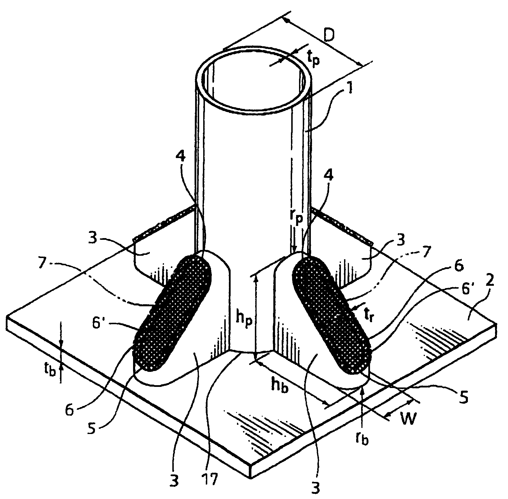
图1是表示本发明的实施方案的立体图。Fig. 1 is a perspective view showing an embodiment of the present invention.
图2(a)是表示本发明的其它实施方案的平面图。Fig. 2(a) is a plan view showing another embodiment of the present invention.
图2(b)是表示本发明的其它实施方案的平面图。Fig. 2(b) is a plan view showing another embodiment of the present invention.
图3(a)是表示本发明的其它实施方案的立体图。Fig. 3(a) is a perspective view showing another embodiment of the present invention.
图3(b)是表示本发明的其它实施方案的立体图。Fig. 3(b) is a perspective view showing another embodiment of the present invention.
图4(a)是表示本发明的其它实施方案的立体图。Fig. 4(a) is a perspective view showing another embodiment of the present invention.
图4(b)是表示本发明的其它实施方案的立体图。Fig. 4(b) is a perspective view showing another embodiment of the present invention.
图5是表示封闭图1中的加固件的开口部的一部分的实施方案的立体图。Fig. 5 is a perspective view showing an embodiment in which a part of an opening of the reinforcing member in Fig. 1 is closed.
图6(a)是表示制造由两个板状构件构成的加固件的方法的立体图。Fig. 6(a) is a perspective view showing a method of manufacturing a reinforcing member composed of two plate-shaped members.
图6(b)是表示制造由两个板状构件构成的加固件的其它方法的立体图。Fig. 6(b) is a perspective view showing another method of manufacturing a reinforcing member composed of two plate-shaped members.
图6(c)是表示制造由四个板状构件构成的加固件的方法的立体图。Fig. 6(c) is a perspective view showing a method of manufacturing a reinforcing member composed of four plate-shaped members.
图7是表示制造由筒状构件构成的加固件的方法的立体图。Fig. 7 is a perspective view showing a method of manufacturing a reinforcement made of a cylindrical member.
图8是以往的接合结构体的立体图。Fig. 8 is a perspective view of a conventional bonded structure.
图9是表示以往的接合结构体的立体图。FIG. 9 is a perspective view showing a conventional bonded structure.
具体实施方式Detailed ways
根据附图说明本发明的实施方案。图1是表示作为本发明的一实施方案的在柱状结构构件和作为其它的结构构件的板状结构构件之间间隔90度地配置有4个加固件的接合结构体的立体图,图2(a)、图2(b)是表示在柱状结构构件和板状结构构件之间间隔180度地配置2个加固件的接合结构体的平面图,图3(a)、图3(b)是表示在柱状结构构件和与其交叉的其它的柱状结构构件之间配置加固件的接合构件体的立体图,图4(a)、图4(b)是表示在柱状结构构件和与其交叉的多个其它的柱状结构构件之间配置加固件的接合构件体的立体图。Embodiments of the present invention are described with reference to the drawings. 1 is a perspective view showing a joint structure in which four reinforcing members are arranged at intervals of 90 degrees between a columnar structural member and a plate-shaped structural member as another structural member according to an embodiment of the present invention. FIG. 2(a ), Figure 2(b) is a plan view showing a joint structure in which two reinforcements are arranged at intervals of 180 degrees between a columnar structural member and a plate-shaped structural member, and Figure 3(a) and Figure 3(b) are shown in A perspective view of a joint member body in which reinforcements are arranged between a columnar structural member and other columnar structural members intersecting with it. FIG. 4(a) and FIG. A perspective view of a joined member body with stiffeners disposed between structural members.
图5是表示封闭了图1中加固件的开口部的一部分之后的状态下的接合结构体的立体图。图6(a)、图6(b)、图6(c)是表示焊接成形加工而成的两个或其以上的板状构件、制造加固件的方法的示例的立体图。图7是表示制造被成形加工的筒状构件所形成的加固件的方法的立体图。Fig. 5 is a perspective view showing a joined structure in a state where a part of an opening of the reinforcing member in Fig. 1 is closed. 6( a ), FIG. 6( b ), and FIG. 6( c ) are perspective views illustrating an example of a method of manufacturing two or more plate-shaped members formed by welding and forming a reinforcing member. Fig. 7 is a perspective view showing a method of manufacturing a reinforcing member formed of a formed cylindrical member.
在图1所示的接合结构体的实施方案中,1是柱状结构构件,2是作为被焊接在柱状结构构件1的下端的其它的结构构件的板状结构构件,3是以90度间隔焊接在柱状结构构件1和板状结构构件2之间的加固件,其以从柱状结构构件1和板状结构构件2突出的方式被设置。在焊接于柱状结构构件1上的加固件3的距离柱状结构构件1和板状结构构件2的接合部17较远一侧的端部、即在上端部4上,沿着柱状结构构件1的表面的加固件3的截面形状,呈U字形或V字形弯曲。此外,在焊接于板状结构构件2上的加固件3的距离柱状结构构件1和板状结构构件2的接合部17较远一侧的端部、即在下端部5上,沿着板状结构构件2的表面的截面形状呈U字形或V字形弯曲。由这些上下端部的弯曲部,在加固件3上与上述柱状结构构件1、板状结构构件2不相接的一侧,形成不含加固件3的板厚tr的空间即开口部6。即,开口部6,是由图1中加固件3的与柱状结构构件1和板状结构构件2的两个结构构件不相接的一侧的端部所包围、由加固件3的内缘所形成的空间。此外,在图1中端面6′,是由加固件3的与柱状结构构件1及板状结构构件2的两结构构件不相接的一侧的端部所形成的端面,包含加固件3的板厚tr。通常,开口部6及端面6′具有长径、短径而呈椭圆形。此外,在此实施方案中,开口部6的大小,为从端面6′减去加固件3的板厚tr所得的大小。在此实施方案的接合结构体中,由于使加固件3的上下端部4、5向避开柱状结构构件1及板状结构构件2的主应力方向的方向弯曲成U字形或V字形,故能够使加固件3的上下端部4、5成为低刚性结构。其结果,能够使加固件3的上下端部4、5处的应力集中得到大幅度的缓和,同时使焊接部的焊接残余应力也得到大幅度的缓和,使作为接合结构体的屈服强度或疲劳强度大幅度提高。为了能充分发挥这种效果,优选将加固件的上下端部4、5的弯曲部的弯曲半径预先设为加固件3的板厚的3倍或其以上。如果弯曲半径比其小,则在使加固件3弯曲时易导致材质劣化,此外减低刚性的效果也变小。此外,虽然仅在加固件3的外侧进行加固件3和柱状结构构件1及板状结构构件2的焊接也可以,但是优选还从加固件3的内侧进行焊接。此外,为了避免柱状结构构件1和板状结构构件2的焊接部与加固件3的重合,可以在加固件3的与柱状结构构件1和板状结构构件2的焊接部17相对应的位置、即与开口部相反一侧的加固件3的内侧的角部,设置弧形缺口(スカ一ラップ)。优选在加固件3的开口部6上设置用于防止雨水、尘埃的侵入的盖部件7(如图1的网格线所示)。若盖部件7的板厚小于或等于加固件3的板厚就可以缓和其作用在加固件3上的应力。另外,盖部件7的板厚优选为加固件3的板厚的0.5倍或其以下。此外,盖部件7的材质优选比加固件3的材质还软。可以在开口部填充发泡树脂等的填充材料来代替设置盖部件7。另外,如在图1~7中所说明的那样,开口部、端面以及空间具有圆形、椭圆形或带圆角的多边形状。In the embodiment of the joint structure shown in FIG. 1, 1 is a columnar structural member, 2 is a plate-shaped structural member as other structural members welded to the lower end of the columnar
图2(a)、图2(b)所示的接合结构体的实施方案,在柱状结构构件1的下端焊接窄幅的板状结构构件2,在柱状结构构件1和窄幅的板状结构构件2之间,相对于柱状结构构件1仅在一对相对的位置上焊接配置有与图1所示的实施方案同样的加固件3。图2(a)是Y方向的板幅压缩(制约)较强、但X方向的板幅压缩较缓和的情况,图2(b)是X方向的板幅压缩以较强的情况(板状结构构件2的X方向的幅度仅为柱状结构构件1的外径的3倍左右的情况)。在图2(b)那样的情况下,加固件3的宽度W、即与连结加固件的中心和柱状结构构件1的中心的轴线相垂直的方向(Y轴方向)上的长度,优选为接近柱状结构构件1的宽度、设为柱状结构构件的宽度的70%或其以上,若考虑加工性上限优选在95%或其以下。更优选在加固件3的开口部6上设置盖部件7。The embodiment of joint structure shown in Fig. 2 (a), Fig. 2 (b), in the lower end of columnar
相对于柱状结构构件1仅在一对相对的位置上配置的加固件3被设计为,相对于绕其中心线面与板状结构构件2的面的交线X轴及绕与其垂直的Y轴的弯曲力矩,可确保足够的刚性及强度。为了抵抗绕Y轴的弯曲力矩,由于通过确保加固件3的板厚t和伸出长度L有必要尺寸就可以实现,因此即使底板等的板状结构构件2为窄幅的形状也可以应对。The reinforcing
为了应付绕X轴的弯曲力矩,在使用窄幅的板状结构构件2的情况下,在沿宽度方向(Y轴方向)不能设置加固件3的限制下,优选将加固件3的宽度W(跨度宽度)加宽。In order to cope with the bending moment around the X-axis, in the case of using a narrow plate-shaped
所谓加固件3的宽度(跨度宽度)W,如图2所示,是指加固件3的焊接在板状结构构件2上的部分的Y轴方向的宽度的最大值。The width (span width) W of the reinforcing
在柱状结构构件1为圆形钢管柱的情况下,设柱状结构构件1的宽度为直径D、板厚为t,截面二次矩(二次モ一メント)(I1)与截面系数(Z1)为:In the case that the columnar
I1=(π/64)×{D4-(D-2·t)4}(π/8)×D3·tI 1 =(π/64)×{D 4 -(D-2·t) 4 }(π/8)×D 3 ·t
Z1=(π/3 2)×{D3-(D-2·t)3}(π/4)×D2·tZ 1 =(π/3 2)×{D 3 -(D-2·t) 3 }(π/4)×D 2 ·t
另一方面,加固件3的底面的截面二次矩(I2)与截面系数(Z2)为:On the other hand, the second moment of section (I 2 ) and section modulus (Z 2 ) of the bottom surface of the reinforcing
I2=L·W2·tI 2 = L·W 2 ·t
Z2=2L·W·tZ 2 =2L·W·t
因此,用于使I2与I1相等的W的下限值Wa为:Therefore, the lower limit value Wa of W for making I2 equal to I1 is:
Wa={(π/8L)×D3}Wa={(π/8L)×D 3 }
用于使Z2与Z1相等的W的下限值Wb为:The lower limit value Wb of W for making Z 2 equal to Z 1 is:
Wb=(π/8L)×D2 Wb=(π/8L)×D 2
在此,在实际的施工中,由于像图2(b)那样X方向的板幅也受到压缩的情况较多,且L=0.75D左右的情况较多,故Here, in actual construction, as shown in Fig. 2(b), the board width in the X direction is often compressed, and L=0.75D in many cases, so
Wa={(π/6D)×D3}=0.72DWa={(π/6D)×D 3 }=0.72D
Wb=(π/8L)×D2=0.52DWb=(π/8L)×D 2 =0.52D
因此,加固件3的宽度W优选为接近柱状结构构件1的宽度,具体地说优选为柱状结构构件1的宽度的0.7~0.95倍。Therefore, the width W of the reinforcing
图3(a)、图3(b)所示的接合结构体的实施方案,是在柱状结构构件1的下端接合有沿与上述柱状结构构件1交叉的方向延伸的其它的柱状结构构件8、在柱状结构构件1和其它的柱状结构构件8之间配置有与图1及图2所示同样的加固件3的方案。在图中,虽然加固件3仅配置有1个,但在有必要进一步加固的情况下,也可以夹着柱状结构构件1相面对地进一步配置加固件3。另外,优选在加固件3的开口部6上设置盖部件7。The embodiment of the joined structure shown in Fig. 3 (a), Fig. 3 (b) is that the lower end of the columnar
图4(a)、图4(b)所示的接合结构体的实施方案,在柱状结构构件1上交叉接合有多个其它的柱状结构构件8(图为2个的例子)、在柱状结构构件1和多个其它的柱状结构构件8之间配置有与图1、图2及图3所示的同样的加固件3。其它的柱状结构构件8的对柱状结构构件1的交叉角度并不限于90度,以任何角度交叉都可以适用。优选在加固件3的开口部6上设置盖部件7。The embodiment of the joint structure shown in Fig. 4 (a), Fig. 4 (b), on the columnar
图5所示的接合结构体的实施方案,是将图1所示的接合结构体的开口部的一部分用具有与加固件3的板厚同等厚度或其以上的厚度的板状构件18封住的方案。即,图5所示加固件3的开口部6的长径,变得比由加固件3的与柱状结构构件1及其它结构构件2不相接的一侧的端部所形成的面、即端面6′的长径还短,开口部6变小。该开口部6的长径,只要是端面6′的长径的0.5倍或其以上就可以缓和作用于加固件3上的应力。此外,开口部6的长径,优选为端面6′的长径的0.8倍或其以上。开口部6的长径相对于端面6′的长径的比,如图1所示,在开口部未被封闭的情况下最大,开口部6的长径相对于端面6′的长径的比的最大比值,随着加固件3的形状及板厚而变化。这种情况下,开口部6的长径不足端面6′的长径的1倍。此外,最好在开口部上设置长径比图1~图4所示的短的盖部件7。In an embodiment of the joint structure shown in FIG. 5, a part of the opening of the joint structure shown in FIG. scheme. That is, the major diameter of the
本发明的加固件,可以通过对两个或其以上的板状构件进行弯曲加工、并进行焊接而形成。例如,如图6(a)所示,只要通过压力加工形成形状为可将加固件3用与单点划线平行的纵剖面在弯曲部一分为二的板状构件19、20,并将弯曲部相互对接焊接即可。此外,如图6(b)所示,也可以是通过压力加工形成形状为可将加固件以与短径平行的剖面、如与连结加固件的开口部的短径和成为柱状结构构件与其它结构构件的接合部分附近的角部的单点划线平行的截面一分为二的板状构件21、22,再使两个构件以形成开口部的方式对接焊接。此外,如图6(c)所示,也可以分离U字形部分,制造两个5边形的板状构件23、24和两个U字形构件25、26,将四个构件在单点划线所示的位置对接焊接。The reinforcement of the present invention can be formed by bending and welding two or more plate-shaped members. For example, as shown in FIG. 6(a), as long as the shape is formed by press working, the reinforcing
此外,本发明的加固件,也可以通过将板材压力加工成图1的开口部为底面那样的形状来进行制造。这种情况下,可以通过将压力加工的板材的底面的一部分或前部切断而设置孔,来形成开口部。根据板材的材质、板厚不同,可以在进行压力加工前预热板材。In addition, the reinforcing member of the present invention can also be produced by press-working a plate material into a shape in which the opening in FIG. 1 is the bottom surface. In this case, the opening can be formed by cutting a part of the bottom surface or the front part of the press-worked plate material to form a hole. According to the material and thickness of the plate, the plate can be preheated before pressure processing.
进而,本发明的加固件,如图7所示,可以通过切断筒状构件27来进行制造。只要将该筒状的构件27的截面作为开口部6,并按照使其位于距离柱状结构构件1和其它结构构件2的接合部较远的一侧的方式进行焊接即可。这种情况下,图7中单点划线所示的筒状的构件27的切断部,只要形成为沿着与焊接在柱状结构构件1及其它结构构件2上的位置相对应的两结构构件的表面形状那样的形状即可。另外,筒状的构件27,也可以扁平地形成而使截面成为椭圆形状。筒状的构件27,例如可以通过将电焊钢管(电焊缝钢管)或无缝钢管以其原有的形状、或压力加工成扁平形状来制造。在将如此所制造的加固件,焊接到例如将柱状结构构件垂直接合到板状结构构件上而成的结构体上的情况下,加固件的U字形或V字形的弯曲部的顶部棱线,就成为相对于柱状结构构件的轴线倾斜的状态。Furthermore, the reinforcing material of the present invention can be produced by cutting the
此外,本发明的加固件,也可以通过例如将图9所示的以往的加固件13的开口端16的前端弯曲成U字形、并使前端相互对接并进行焊接而制造。即,通过使如图9所示的在上端15上具有U字形或V字形的弯曲部、在另端具有开口端16的加固件13的、被形成在与柱状结构构件10和板状结构构件11不相接触的一侧的开口面的开口端部16的前端弯曲成U字形或V字形,并使其前端相互焊接接合,从而形成为开口部6。In addition, the reinforcing member of the present invention can also be manufactured by, for example, bending the front end of the opening
实施例Example
在图1所示的实施方案中,设柱状结构构件的外径D:163mm、柱状结构构件的壁厚tp:4.5mm、板状结构构件的壁厚tb:25mm、加固件的壁厚tr:6.0mm、加固件的柱状结构构件侧的长度hp:200mm、加固件的板状结构构件侧的长度hb:100mm、加固件的宽度W:40mm、加固件的柱状结构构件侧(上端部)的弯曲半径rp:40mm、加固件的板状结构构件侧(下端部)的弯曲半径rb:40mm,实施了在柱状结构物1上加载水平力的试验,结果证明其具有足够的屈服强度。In the embodiment shown in Fig. 1, the outer diameter D of the columnar structural member is 163 mm, the wall thickness tp of the columnar structural member is 4.5 mm, the wall thickness tb of the plate-shaped structural member is 25 mm, and the wall thickness tr of the reinforcing member is: 6.0 mm, length hp of the columnar structural member side of the reinforcement: 200 mm, length hb of the plate-shaped structural member side of the reinforcement: 100 mm, width W of the reinforcement: 40 mm, columnar structural member side (upper end) of the reinforcement Bending radius rp: 40 mm, bending radius rb of the plate-shaped structural member side (lower end) of the stiffener: 40 mm, and a test in which a horizontal force was applied to the
Claims (14)
Applications Claiming Priority (2)
| Application Number | Priority Date | Filing Date | Title |
|---|---|---|---|
| JP2003199723 | 2003-07-22 | ||
| JP199723/2003 | 2003-07-22 |
Publications (2)
| Publication Number | Publication Date |
|---|---|
| CN1576680A CN1576680A (en) | 2005-02-09 |
| CN1328537C true CN1328537C (en) | 2007-07-25 |
Family
ID=34113604
Family Applications (1)
| Application Number | Title | Priority Date | Filing Date |
|---|---|---|---|
| CNB2004100546337A Expired - Lifetime CN1328537C (en) | 2003-07-22 | 2004-07-22 | Jointing structural body |
Country Status (4)
| Country | Link |
|---|---|
| US (1) | US7182543B2 (en) |
| KR (1) | KR20050012160A (en) |
| CN (1) | CN1328537C (en) |
| TW (1) | TWI273157B (en) |
Cited By (1)
| Publication number | Priority date | Publication date | Assignee | Title |
|---|---|---|---|---|
| CN104005493A (en) * | 2014-06-18 | 2014-08-27 | 桂林理工大学 | Method for manufacturing aseismic structure column foot |
Families Citing this family (11)
| Publication number | Priority date | Publication date | Assignee | Title |
|---|---|---|---|---|
| KR100939406B1 (en) * | 2007-10-31 | 2010-01-28 | 구희정 | Reinforcement plate joining structure of pontoon base |
| KR101090806B1 (en) * | 2009-10-08 | 2011-12-08 | 현대자동차주식회사 | Stabilizer link mounting unit for shock absorber |
| BR112012013384A2 (en) | 2009-12-02 | 2016-03-01 | Nippon Steel Corp | structure |
| ES2387143B1 (en) * | 2010-10-21 | 2013-04-15 | Europea De Construcciones Metalicas, S.A. | "DIRECT CONNECTION BETWEEN A TUBE AND A FLAT ELEMENT" |
| US8573550B1 (en) * | 2011-04-28 | 2013-11-05 | The United States Of America, As Represented By The Secretary Of The Army | Radar antenna safety brace |
| GB201214381D0 (en) * | 2012-08-13 | 2012-09-26 | Offshore Design Engineering Ltd | Plated tower transition piece |
| US20140223745A1 (en) | 2013-02-08 | 2014-08-14 | Davis Eberhart | Bolted Structural Connection Systems |
| US20150056004A1 (en) * | 2013-08-23 | 2015-02-26 | Geoffrey Tyler Mitchell | Fatigue Resistant Structural Connection |
| DE102014219482A1 (en) * | 2014-09-25 | 2016-03-31 | Rwe Innogy Gmbh | Transition piece for wind turbines and connection structures |
| CN107461386B (en) * | 2017-09-21 | 2023-04-07 | 上海振华重工(集团)股份有限公司 | Pipe-tube covered rigid joint |
| USD1057215S1 (en) * | 2023-04-21 | 2025-01-07 | Worxsafe Ab | Holder for a post |
Citations (5)
| Publication number | Priority date | Publication date | Assignee | Title |
|---|---|---|---|---|
| US4825621A (en) * | 1987-12-10 | 1989-05-02 | Mitek Industries, Inc. | Holddown |
| US5467570A (en) * | 1994-10-12 | 1995-11-21 | Simpson Strong-Tie Co., Inc. | Tension tie |
| WO1998055771A1 (en) * | 1997-06-03 | 1998-12-10 | Rueger Ulrich | Joining element for a joint which is glued between two or more bars |
| JP2001132102A (en) * | 1999-08-26 | 2001-05-15 | Nippon Steel Corp | Joint structure |
| JP2003001476A (en) * | 2001-06-19 | 2003-01-08 | Nippon Steel Corp | Steel tube column base and method of strengthening steel tube column base |
Family Cites Families (10)
| Publication number | Priority date | Publication date | Assignee | Title |
|---|---|---|---|---|
| US4219285A (en) * | 1977-06-20 | 1980-08-26 | Hayashi Henry T | Clamp-connector for joining three tubular members |
| DK153507C (en) * | 1986-01-23 | 1988-12-19 | Kjeld Thomsen | PROCEDURE FOR COLLECTION OF CROSS-CIRCULAR CIRCUIT GRID STARS AND A MEASURE TO USE IN EXERCISING THE PROCEDURE |
| US5481835A (en) * | 1989-05-12 | 1996-01-09 | Adian Engineering Corporation | Breakaway base and upper-separation joint |
| US5205529A (en) * | 1991-08-02 | 1993-04-27 | Eaton Corporation | Friction-dampened gusset |
| US5853651A (en) * | 1995-09-07 | 1998-12-29 | Simula, Inc. | High pressure hollow process for manufacturing composite structures |
| EP0897016B8 (en) | 1997-01-24 | 2007-04-25 | Nippon Steel Corporation | Grain-oriented electrical steel sheet having excellent magnetic characteristics, its manufacturing method and its manufacturing device |
| US6668417B1 (en) * | 2000-03-17 | 2003-12-30 | Anthony D. Slattery | Handle systems for hand floats |
| US6379074B1 (en) * | 2000-05-08 | 2002-04-30 | Hsueh-Hung Chin | Coupler structure for steel pipe conjoinment stabilization |
| US6726170B2 (en) * | 2002-02-07 | 2004-04-27 | Beijing Trade Exchange, Inc. | Dual position flag pole bracket |
| GB2387394B (en) * | 2002-04-11 | 2004-06-09 | Presco Pressings | Fence panel and connector therefor |
-
2004
- 2004-07-21 TW TW093121751A patent/TWI273157B/en not_active IP Right Cessation
- 2004-07-22 US US10/896,508 patent/US7182543B2/en not_active Expired - Lifetime
- 2004-07-22 KR KR1020040057276A patent/KR20050012160A/en not_active Ceased
- 2004-07-22 CN CNB2004100546337A patent/CN1328537C/en not_active Expired - Lifetime
Patent Citations (5)
| Publication number | Priority date | Publication date | Assignee | Title |
|---|---|---|---|---|
| US4825621A (en) * | 1987-12-10 | 1989-05-02 | Mitek Industries, Inc. | Holddown |
| US5467570A (en) * | 1994-10-12 | 1995-11-21 | Simpson Strong-Tie Co., Inc. | Tension tie |
| WO1998055771A1 (en) * | 1997-06-03 | 1998-12-10 | Rueger Ulrich | Joining element for a joint which is glued between two or more bars |
| JP2001132102A (en) * | 1999-08-26 | 2001-05-15 | Nippon Steel Corp | Joint structure |
| JP2003001476A (en) * | 2001-06-19 | 2003-01-08 | Nippon Steel Corp | Steel tube column base and method of strengthening steel tube column base |
Cited By (1)
| Publication number | Priority date | Publication date | Assignee | Title |
|---|---|---|---|---|
| CN104005493A (en) * | 2014-06-18 | 2014-08-27 | 桂林理工大学 | Method for manufacturing aseismic structure column foot |
Also Published As
| Publication number | Publication date |
|---|---|
| US7182543B2 (en) | 2007-02-27 |
| TW200510612A (en) | 2005-03-16 |
| CN1576680A (en) | 2005-02-09 |
| TWI273157B (en) | 2007-02-11 |
| KR20050012160A (en) | 2005-01-31 |
| US20050028478A1 (en) | 2005-02-10 |
Similar Documents
| Publication | Publication Date | Title |
|---|---|---|
| CN1328537C (en) | Jointing structural body | |
| EP3257690B1 (en) | Structure for bonding press-molded article, structural article for automobile having said bonding structure, and method for manufacturing bonded article | |
| CN104508220B (en) | The axial surrender delayed support member of type elastoplasticity and vibration-damp steel shelf structure thing | |
| KR101826491B1 (en) | Fillet welded joint and manufacturing method thereof | |
| JP4902035B2 (en) | Structure | |
| KR20020059589A (en) | Connected structural body | |
| JP6879442B2 (en) | Vehicle skeleton member | |
| US7654571B2 (en) | Joining structure for side members and cross members in chassis frames | |
| US10590974B2 (en) | Lap fillet arc-welded joint | |
| JP6579139B2 (en) | Fillet welded joint structure of closed cross-section member of car body | |
| JP3836683B2 (en) | Working arm structure of work machine | |
| CN107598405B (en) | Welded member, variable cross-section box member, and welding method | |
| US20250128770A1 (en) | Joining structure and joining method for vehicle member | |
| JP4181094B2 (en) | Bonding structure | |
| JP5216057B2 (en) | Passenger conveyor | |
| JP7812225B2 (en) | Buckling Restrained Brace | |
| JPS60131376A (en) | Joint structure of pillar and side sill | |
| JP2024153302A (en) | Housing and device having the same | |
| JP7754674B2 (en) | Beams with end plates and beam-to-column joints | |
| CN202175351U (en) | Rear corner column of container and container with same | |
| JP4698199B2 (en) | Closed section welded structure and manufacturing method thereof | |
| JP2006002464A (en) | Bonding structure | |
| JP2025171666A (en) | Brace | |
| JP6992954B2 (en) | Body skeleton joint structure | |
| JPH0544808B2 (en) |
Legal Events
| Date | Code | Title | Description |
|---|---|---|---|
| C06 | Publication | ||
| PB01 | Publication | ||
| C10 | Entry into substantive examination | ||
| SE01 | Entry into force of request for substantive examination | ||
| C14 | Grant of patent or utility model | ||
| GR01 | Patent grant | ||
| C56 | Change in the name or address of the patentee |
Owner name: NIPPON STEEL + SUMITOMO METAL CORPORATION Free format text: FORMER NAME: SHIN NIPPON STEEL LTD. |
|
| CP01 | Change in the name or title of a patent holder |
Address after: Tokyo, Japan Patentee after: NIPPON STEEL & SUMITOMO METAL Corp. Address before: Tokyo, Japan Patentee before: NIPPON STEEL Corp. |
|
| CP01 | Change in the name or title of a patent holder |
Address after: Tokyo, Japan Patentee after: NIPPON STEEL & SUMITOMO METAL Corp. Address before: Tokyo, Japan Patentee before: NIPPON STEEL & SUMITOMO METAL Corp. |
|
| CP01 | Change in the name or title of a patent holder | ||
| CX01 | Expiry of patent term |
Granted publication date: 20070725 |
|
| CX01 | Expiry of patent term |