CN1330902A - Dispenser end sheet including integrally associated portions and short fiber dressing - Google Patents
Dispenser end sheet including integrally associated portions and short fiber dressing Download PDFInfo
- Publication number
- CN1330902A CN1330902A CN01129688A CN01129688A CN1330902A CN 1330902 A CN1330902 A CN 1330902A CN 01129688 A CN01129688 A CN 01129688A CN 01129688 A CN01129688 A CN 01129688A CN 1330902 A CN1330902 A CN 1330902A
- Authority
- CN
- China
- Prior art keywords
- dististyle
- short fiber
- arbitrary
- fiber dressing
- end piece
- Prior art date
- Legal status (The legal status is an assumption and is not a legal conclusion. Google has not performed a legal analysis and makes no representation as to the accuracy of the status listed.)
- Granted
Links
Images







Classifications
-
- B—PERFORMING OPERATIONS; TRANSPORTING
- B65—CONVEYING; PACKING; STORING; HANDLING THIN OR FILAMENTARY MATERIAL
- B65D—CONTAINERS FOR STORAGE OR TRANSPORT OF ARTICLES OR MATERIALS, e.g. BAGS, BARRELS, BOTTLES, BOXES, CANS, CARTONS, CRATES, DRUMS, JARS, TANKS, HOPPERS, FORWARDING CONTAINERS; ACCESSORIES, CLOSURES, OR FITTINGS THEREFOR; PACKAGING ELEMENTS; PACKAGES
- B65D83/00—Containers or packages with special means for dispensing contents
- B65D83/14—Containers for dispensing liquid or semi-liquid contents by internal gaseous pressure, i.e. aerosol containers comprising propellant
- B65D83/28—Nozzles, nozzle fittings or accessories specially adapted therefor
- B65D83/285—Nozzles, nozzle fittings or accessories specially adapted therefor for applying the content, e.g. brushes or pads
-
- A—HUMAN NECESSITIES
- A45—HAND OR TRAVELLING ARTICLES
- A45D—HAIRDRESSING OR SHAVING EQUIPMENT; EQUIPMENT FOR COSMETICS OR COSMETIC TREATMENTS, e.g. FOR MANICURING OR PEDICURING
- A45D40/00—Casings or accessories specially adapted for storing or handling solid or pasty toiletry or cosmetic substances, e.g. shaving soaps or lipsticks
- A45D40/26—Appliances specially adapted for applying pasty paint, e.g. using roller, using a ball
-
- B—PERFORMING OPERATIONS; TRANSPORTING
- B65—CONVEYING; PACKING; STORING; HANDLING THIN OR FILAMENTARY MATERIAL
- B65D—CONTAINERS FOR STORAGE OR TRANSPORT OF ARTICLES OR MATERIALS, e.g. BAGS, BARRELS, BOTTLES, BOXES, CANS, CARTONS, CRATES, DRUMS, JARS, TANKS, HOPPERS, FORWARDING CONTAINERS; ACCESSORIES, CLOSURES, OR FITTINGS THEREFOR; PACKAGING ELEMENTS; PACKAGES
- B65D83/00—Containers or packages with special means for dispensing contents
- B65D83/76—Containers or packages with special means for dispensing contents for dispensing fluent contents by means of a piston
- B65D83/761—Containers or packages with special means for dispensing contents for dispensing fluent contents by means of a piston the piston being actuated by a screw-shaft
Landscapes
- Engineering & Computer Science (AREA)
- Mechanical Engineering (AREA)
- Chemical & Material Sciences (AREA)
- Dispersion Chemistry (AREA)
- Containers And Packaging Bodies Having A Special Means To Remove Contents (AREA)
- Coating Apparatus (AREA)
- Closures For Containers (AREA)
- Nozzles (AREA)
- Brushes (AREA)
Abstract
一种涂抹化妆品或养护品的端片,该端片包括与第二部分组装的第一部分,该两个部分之一确定至少一涂抹器表面部分,适合于通过端片上的至少一个小孔为其供应物质,第二部分具有短纤维敷层,该敷层延伸至:所述第二部分的至少一边缘部分,其大体上与第一部分的没有短纤维敷层的相应边缘部分接触;和/或一个大体上与第一部分的没有短纤维敷层的相应边缘部分接触的一条轮廓线,附着短纤维硬毛的第二部分的表面从第一部分的边缘部外表面向后退。
An end piece for applying cosmetics or skin care products, the end piece comprising a first part assembled with a second part, one of the two parts defining at least one applicator surface portion adapted to pass through at least one small hole in the end piece for its supplying the substance, the second portion has a staple fiber coating extending to: at least one edge portion of said second portion substantially in contact with a corresponding edge portion of the first portion without the staple fiber coating; and/or A contour line substantially in contact with the corresponding edge portion of the first portion without the staple fiber coating, the surface of the second portion to which the short fiber bristles are attached recedes from the outer surface of the edge portion of the first portion.
Description
本发明涉及一种涂抹化妆品或养护品的装置,特别是将其涂抹于嘴唇、眼睑的装置。The invention relates to a device for applying cosmetics or maintenance products, especially a device for applying the same to lips and eyelids.
已知带短纤维的涂抹器端片是为了使其保持更多的物质并增加涂抹时的舒适性。Applicator tips with staple fibers are known in order to allow them to hold more substance and increase comfort while applying.
为了制造一个带短纤维的端片,已知开始通过在端片上涂敷粘接剂,随后通过静电装置沉积短硬毛。In order to produce an end piece with staple fibers, it is known to start by applying an adhesive to the end piece, followed by deposition of short bristles by electrostatic means.
获得一个具有明显清晰外轮廓的短纤维敷层是不容易的。It is not easy to obtain a staple fiber layup with a sharp and sharp outer contour.
不幸的是,产品没有一个明显清晰外轮廓在外观上是不吸引人的,并且使其更加难于进行整洁优美的化妆。Unfortunately, products without a clearly defined outline are unattractive in appearance and make it more difficult to apply a clean and polished finish.
本发明的目的特别是寻找一种克服上述缺陷的途径。The object of the present invention is in particular to find a way to overcome the above-mentioned disadvantages.
因此,本发明的一个目的是提供一种易于制造的端片,其能够确定一个适于整洁优美化妆的涂抹器表面,并且使用起来舒适。It is therefore an object of the present invention to provide an easy-to-manufacture end-piece capable of defining an applicator surface suitable for clean and elegant makeup and comfortable to use.
本发明的端片包括一个与一第二部分组装起来的第一部分,两个部分之一确定了至少一个涂抹器表面部分,该表面部分适合于通过端片上的至少一个小孔为其供应物质,该第二部分具有一个短纤维敷层,该敷层延伸至:The end piece of the present invention comprises a first part assembled with a second part, one of the two parts defining at least one applicator surface portion adapted to supply substance thereto through at least one aperture in the end piece, The second part has a staple fiber coating extending to:
●所述第二部分的至少一个边缘部分,所述边缘部分大体上与第一部分的一个没有短纤维敷层的相应边缘部分接触;和/或- at least one edge portion of said second portion substantially in contact with a corresponding edge portion of the first portion without the staple fiber coating; and/or
●一个大体上与第一部分的一个没有短纤维敷层的相应边缘部分接触的一条轮廓线,附着短纤维硬毛的第二部分的表面从第一部分的边缘部外表面向后退。• A contour line substantially in contact with a corresponding edge portion of the first portion without the staple fiber coating, the surface of the second portion to which the staple fiber bristles are attached is set back from the outer surface of the edge portion of the first portion.
术语“大体上接触的边缘部分”意味着彼此相互接触或彼此直接相邻的边缘部分,给定了制造公差。The term "substantially touching edge portions" means edge portions that are in contact with each other or directly adjacent to each other, given manufacturing tolerances.
本发明能够获得一个具有明显清晰外轮廓的短纤维敷层,由此改善了端片的外观,并且改善了化妆质量。The present invention makes it possible to obtain a staple fiber coating with a distinctly defined outer contour, thereby improving the appearance of the end pieces and improving the cosmetic quality.
此外,采用两个组装在一起的部分使得易于制造短纤维敷层,因为所述部分中的一个能够更容易地被单独粘敷,能够减少堵塞用于为短纤维敷层供应物质的小孔的危险。Furthermore, the use of two parts assembled together makes it easier to manufacture the staple fiber layup, since one of the parts can be more easily adhered alone, reducing the chance of clogging the small holes used to supply the staple fiber layup. Danger.
在一个特定实施例中,第二部分具有一个短纤维敷层,其延伸到所述第二部分的至少一个边缘部分,该边缘部分大体上与第一部分的一个没有短纤维敷层的相应边缘部分接触,第二部分的边缘部分由一个边缘确定。In a particular embodiment, the second portion has a staple fiber coating that extends to at least one edge portion of said second portion that is substantially identical to a corresponding edge portion of the first portion that does not have a staple fiber coating. contact, the edge portion of the second part is defined by an edge.
在一个特定实施例中,第二部分具有一个短纤维敷层,其延伸到所述第二部分的至少一个边缘部分,该边缘部分大体上与第一部分的一个没有短纤维敷层的相应边缘部分接触,第二部分的边缘部分由其自由边确定。In a particular embodiment, the second portion has a staple fiber coating that extends to at least one edge portion of said second portion that is substantially identical to a corresponding edge portion of the first portion that does not have a staple fiber coating. contact, the edge portion of the second part is defined by its free edge.
在一个特定实施例中,第二部分具有一个短纤维敷层,其延伸到大体上与第一部分的一个没有短纤维敷层的相应边缘部分接触的一条轮廓线,附着短纤维硬毛的第二部分的表面从第一部分的边缘部分的外表面向后退。In a particular embodiment, the second part has a staple fiber coating extending to substantially a contour line in contact with a corresponding edge portion of the first part without the staple fiber coating, the second portion of the staple fiber bristles attached. The surface of the part is set back from the outer surface of the edge part of the first part.
短纤维敷层的包封表面可位于大体上与第一部分边缘外表面相连贯的位置。The envelope surface of the staple fiber blanket may be located substantially contiguous with the outer surface of the edge of the first portion.
短纤维敷层的包封表面也可以大体上平行于所述端片的轴线,或者可相对于端片轴线横向延伸。The envelope surface of the staple fiber blanket may also be substantially parallel to the axis of the end piece, or may extend transversely with respect to the axis of the end piece.
短纤维敷层不必被第一部分的边缘部分覆盖。The staple fiber blanket does not have to be covered by the edge portion of the first part.
涂抹器表面可被第二部分确定,该部分可以是所述配合部分。The applicator surface may be defined by a second part, which may be said cooperating part.
第二部分可具有一个确定所述涂抹器表面的整体带有短纤维的外表面。The second portion may have an integrally stapled outer surface defining said applicator surface.
涂抹器表面也可至少部分被第一部分确定。The applicator surface may also be at least partially defined by the first portion.
在一个特定实施例中,第一部分具有一个壳体,所述第二部分被固定于其中。In a particular embodiment, the first part has a housing in which the second part is fixed.
该壳体优选具有一个与第二部分形状互补的形状。The housing preferably has a shape that is complementary to the shape of the second part.
第一部分可以包括一个没有短纤维敷层的外部环形裙边。The first portion may comprise an outer annular skirt without a staple fiber coating.
优选地,所述第一部分和第二部分具有密封装置,使得该两部分以不泄露的方式组合在一起。Preferably, said first and second parts have sealing means such that the two parts are brought together in a leak-tight manner.
通过按扣配合方式将两个部分中的其中一个固定在另一个内部。Secure one of the two parts inside the other with a snap fit.
在一种变形中,所述两个部分可通过热封、粘接剂或热压方法相互固定在一起。In a variant, the two parts may be fixed to each other by heat sealing, adhesives or thermocompression.
在一个优选实施例中,第二部分包括一个格栅或由一个格栅构成。In a preferred embodiment, the second part comprises or consists of a grid.
有利地,第二部分包括一个沿一条封闭曲线延伸的环形沟槽或空腔,所述沟槽或空腔可以非圆形。Advantageously, the second portion comprises an annular groove or cavity, which may be non-circular, extending along a closed curve.
所述沟槽或空腔在向着其外部开口的截面处优选不存在任何狭窄部分,这样就使得皮肤或嘴唇表面适当时能够更深地深入其中,以便吸取物质。The grooves or cavities preferably do not have any constrictions in the cross-section that is open to the outside, so that the skin or the surface of the lips can penetrate deeper into them, if appropriate, for the suction of substances.
在一个特定实施例中,第二部分具有不同的高度,以便限定一个倾斜的涂抹器表面。In a particular embodiment, the second portion has a different height so as to define an inclined applicator surface.
所述第二部分可包括与第一部分相互配合的一个件,以便形成一个止回阀,适合于在物质压力的驱使下打开。The second part may comprise a member cooperating with the first part to form a check valve adapted to open under the pressure of the substance.
所述阀用于保护端片上游的物质不被干燥和氧化。The valve is used to protect the material upstream of the end piece from drying and oxidation.
第一部分可以包括一个形成喷嘴导流板的中心部分,该部分位于或对着一个供应物质通道。The first portion may comprise a central portion forming a nozzle deflector located in or opposite a feed material passage.
在一种变形中,第二部分包括一个对着物质供应通道设置的喷嘴导流板形成部分。In one variation, the second portion includes a nozzle deflector forming portion disposed opposite the material supply passage.
涂抹器表面可包括一个斜面和一个围绕该斜面延伸的侧面,所述斜面和侧面都被粘敷短纤维。The applicator surface may include a bevel and a side extending around the bevel, both of which are coated with staple fibers.
所述第二部分可包括一个或多个沟槽或空腔,并且可被延伸过所述沟槽或空腔内表面至少一部分的短纤维敷层覆盖。The second portion may include one or more grooves or cavities, and may be covered by a blanket of staple fibers extending across at least a portion of the inner surface of the grooves or cavities.
有利地,所述一个或多个小孔从涂抹器表面后退至少1mm,物质供应通道通过所述一个或多个小孔开通进入所述沟槽或空腔(一个或多个)的底部。Advantageously, said one or more small holes are set back at least 1mm from the applicator surface through which a substance supply channel opens into the bottom of said groove or cavity(s).
所述沟槽或空腔(一个或多个)可在从涂抹器表面起的一部分高度范围内粘敷短纤维,不会出现短纤维敷层与物质流过分干涉的危险,这是由于所述沟槽或空腔(一个或多个)可以相对较宽,例如两个相对边缘相距大于1mm,该两个边缘之间的距离最好以这种方式选择,即嘴唇或皮肤表面可以够得着包含在其内的物质。The grooves or cavities(s) allow the deposition of short fibers over a portion of the height from the applicator surface without the risk of the short fiber coating interfering unduly with the flow of the substance due to the The groove or cavity(s) may be relatively wide, e.g. more than 1mm between two opposing edges, the distance between the two edges is preferably chosen in such a way that the lips or skin surface can be reached substances contained in it.
所述沟槽或空腔(一个或多个)的存在还有一个优点是,当端片与被化妆处理的皮肤表面接触时,这些沟槽能够吸收在涂抹器表面出现的过量物质,避免这些物质从涂抹器表面被排除掉。The presence of said grooves or cavities(s) also has the advantage that these grooves are able to absorb excess substances present on the surface of the applicator when the end piece is in contact with the cosmetically treated skin surface, avoiding these problems. Substances are expelled from the applicator surface.
在一个特定实施例中,第二部分呈套筒状,在其前面和至少其内外侧表面之一覆盖有短纤维敷层,优选在其整个外表面和其内侧表面的一部分上覆盖短纤维敷层。In a particular embodiment, the second part has the shape of a sleeve covered on its front face and on at least one of its inner and outer surfaces with a staple fiber coating, preferably over its entire outer surface and part of its inner surface. layer.
所述第二部分可以由柔性材料制成。The second part may be made of a flexible material.
一般地说,所述第一部分和/或第二部分可以由从下列材料中选择的一种或多种塑料制成:乙烯-丙烯二烯系单体(EPDM)弹性体、腈类橡胶、乳胶、聚苯乙烯热塑性弹性体(PS)、聚对苯二甲酸乙二醇酯(PET)、聚氨酯(PU)、乙烯醋酸乙烯酯(EVA)、聚氯乙烯(PVC)、“Polynorborden”、或一种相对刚硬的热塑性材料,如聚丙烯(PP)、聚乙烯(PE)、PS、PET、聚碳酸酯(PC)等。Generally speaking, the first part and/or the second part may be made of one or more plastics selected from the following materials: ethylene-propylene diene monomer (EPDM) elastomers, nitrile rubber, latex , polystyrene thermoplastic elastomer (PS), polyethylene terephthalate (PET), polyurethane (PU), ethylene vinyl acetate (EVA), polyvinyl chloride (PVC), "Polynorborden", or a A relatively rigid thermoplastic material, such as polypropylene (PP), polyethylene (PE), PS, PET, polycarbonate (PC), etc.
在一个特定实施例中,短纤维敷层延伸到一个起伏波动的边缘。In a particular embodiment, the staple fiber blanket extends to an undulating edge.
在一个特定实施例中,所述第二部分包括一个中心区域和一个周边区域,它们通过材料桥相互连接。In a particular embodiment, said second portion comprises a central area and a peripheral area, which are interconnected by bridges of material.
这些材料桥不必粘敷短纤维,特别是如果它们从涂抹器表面大大往后退时。These bridges of material do not necessarily stick to the short fibers, especially if they are set back considerably from the applicator surface.
所述第二部分也可以被短纤维完全粘敷。Said second part may also be fully adhered by staple fibers.
在一个特定实施例中,端片具有至少一个给涂抹器表面供应物质的偏心孔。In a particular embodiment, the end piece has at least one off-center hole for supplying the applicator surface with substance.
在一个特定实施例中,第二部分相对于第一部分是偏心设置的,这就使得适当时能够制造一个符合人体工程学的端片。In a particular embodiment, the second part is arranged off-centre with respect to the first part, which makes it possible to produce an ergonomic end piece where appropriate.
第二部分可与第一部分配合而提供一个允许物质在第二部分下面流动、甚至回流的间隙。The second part can cooperate with the first part to provide a gap that allows material to flow, even backflow, under the second part.
本发明还提供了一个包装和涂抹器装置,其特征在于,该装置包括一个如上确定的端片和一个盛放要被供应到端片的物质的容器。The invention also provides a packaging and applicator device characterized in that the device comprises an end piece as defined above and a container containing a substance to be supplied to the end piece.
所述容器可以通过一个与端片第一部分整体而成的本体形成。The container may be formed by a body integral with the first portion of the end piece.
该装置可以包括一个在所述容器内包含的物质上施加压力的活塞,以分配该物质。The device may include a piston that exerts pressure on the substance contained in said container to dispense the substance.
该容器也可以包括一个可压缩壁,其使得通过在其上施加压力例如通过使用者施加压力而分配物质。The container may also include a compressible wall enabling the substance to be dispensed by applying pressure thereon, for example by a user.
该装置也可以包括一个泵。The device may also include a pump.
该储可以是抽取式的,在这种情况下可以再填充。The reservoir can be removable, in which case it can be refilled.
当装置包括一个泵时,容器最好相对于该装置的其余部分可移动,以便为了分配大量物质而启动泵。When the device includes a pump, the container is preferably movable relative to the remainder of the device to enable activation of the pump for dispensing large quantities of substance.
有利地,该装置包括一个封闭帽,其包含至少一个内部关闭件,当该关闭件处于端片适当位置时所述关闭件适合于覆盖物质排出孔。Advantageously, the device comprises a closure cap comprising at least one internal closure adapted to cover the substance discharge orifice when the closure is in place on the end piece.
本发明还提供了一种制造如上限定的端片的方法,其特征在于,第二部分被附着一种短纤维敷层并在第二部分上制造至少一个沟槽或空腔,而不需要在粘敷敷层后刺穿所述沟槽或空腔,也不需要在粘敷短纤维期间在所述沟槽或空腔内插入插入物。The invention also provides a method of manufacturing an end piece as defined above, characterized in that the second part is attached with a staple fiber coating and at least one groove or cavity is made in the second part without the need for Piercing the grooves or cavities after application of the coating also eliminates the need for inserts to be inserted in the grooves or cavities during application of the staple fibers.
因此,该端片的制造工艺就比较简单。Therefore, the manufacturing process of the end piece is relatively simple.
此外,当完成短纤维的粘敷后不穿刺第二部分,没有形成凹凸不平的粗糙部分,或者说不需进行对形成的短纤维敷层的剥离工作,当端片第二部分柔软时例如因其由弹性体制成时尤为重要。In addition, the second part is not pierced after the adhesion of the short fibers is completed, and uneven rough parts are not formed, or it is not necessary to peel off the formed short fiber coating. When the second part of the end piece is soft, for example, This is especially important when it is made of elastomer.
通过阅读下面对本发明的各种非限定性实施例的详细描述并结合附图,就会更好地理解本发明,其中:The invention will be better understood by reading the following detailed description of various non-limiting embodiments of the invention, in conjunction with the accompanying drawings, in which:
图1是本发明的包装和涂抹器装置的一个图解轴向截面图;Figure 1 is a diagrammatic axial sectional view of the packaging and applicator device of the present invention;
图2表示图1的一个局部;Figure 2 represents a part of Figure 1;
图3表示单独的格栅周边部分;Fig. 3 shows a separate grid peripheral part;
图4是端片的部分视图,表示该端片是如何被供应物质的;Figure 4 is a partial view of an end piece showing how the end piece is supplied with a substance;
图5是端片的图解透视图;Figure 5 is a diagrammatic perspective view of an end piece;
图6表示物质是如何被端片的沟槽或空腔回收的;Figure 6 shows how material is recovered by the grooves or cavities of the end piece;
图7表示在接触到端片时嘴唇的皮肤或粘膜是如何变形的,以及嘴唇的皮肤或粘膜是如何接触端片的沟槽或空腔内所包含的物质的;Figure 7 shows how the skin or mucous membrane of the lips deforms upon contact with the end piece, and how the skin or mucous membrane of the lips contacts the substance contained in the groove or cavity of the end piece;
图8到图10是表示本发明另一个实施例的示意性局部轴向剖面图;8 to 10 are schematic partial axial sectional views showing another embodiment of the present invention;
图11是表示本发明又一个实施例的示意性局部轴向剖面图;Figure 11 is a schematic partial axial sectional view showing yet another embodiment of the present invention;
图12到图17表示各种端片形状的图解透视图;Figures 12 to 17 show diagrammatic perspective views of various end piece shapes;
图18到图20表示可以包装物质的各种方式;Figures 18 to 20 illustrate the various ways in which a substance can be packaged;
图21到图22表示两个端片,这两个端片的涂抹器表面分别向外突出和凹进;Figures 21 to 22 show two end pieces with applicator surfaces projecting outwards and recessed respectively;
图23表示一个端片,其中第二部分全部带有短纤维;Figure 23 shows an end piece in which the second part has all staple fibers;
图24到图29表示端片的其它外形;Figures 24 to 29 represent other profiles of end pieces;
图30表示图29所示端片中分离的格栅。Figure 30 shows the grid separated from the end piece shown in Figure 29.
图1表示一个包装和涂抹器装置,该装置包括一个涂抹物质的端片11,一个限定了一盛装化妆品或养护品P的容器12的本体18,和一个使得大量物质被分配供应的机构13。Figure 1 shows a packaging and applicator device comprising an
通过实施例的方式,物质P的粘度可在0.6帕斯卡秒(Pa.s)到17Pa.s范围内。By way of example, the viscosity of substance P may range from 0.6 Pascal seconds (Pa.s) to 17 Pa.s.
端片11包括第一部分或基部14,及与之配合的一第二部分或格栅15,下面描述其配合方式。The
上述机构13具有一个螺纹杆17,其拧入本体18内的一个孔中,并且适合于借助一个驱动旋钮19被旋转,所述驱动旋钮位于装置10的底部。The above-mentioned mechanism 13 has a threaded rod 17 screwed into a hole in the body 18 and adapted to be turned by means of a drive knob 19 located at the bottom of the device 10 .
一个活塞20与螺纹杆17相啮合,并且活塞可以平移移动与本体18接触,同时被防止相对于本体旋转,以致旋转旋钮19引起活塞20的轴向移动,由此通过在本体18顶部提供的通道30而排出大量物质。A piston 20 engages the threaded rod 17 and the piston is movable in translation into contact with the body 18 while being prevented from rotating relative to the body so that rotation of the knob 19 causes axial movement of the piston 20 thereby passing through a passage provided at the top of the body 18 30 while expelling a large amount of material.
在该实施例中,通过模制一种相对刚硬的塑料材料,端片11的基部14与本体18整体而成,基部14包括一个围绕壳体24的管状裙边23,在该壳体24中固定有格栅15。In this embodiment, the
就是通过这样的基部14而给格栅15供应物质。It is through such a
在不超出本发明范围的前提下,格栅15可以以各种不同方式被固定在基部14上。The
例如,如图所示,可以借助在格栅15上形成的凸起26以防泄露的方式按扣配合在管状裙边23的内表面中形成的一个互补环形槽内来固定格栅。For example, the grille may be secured by means of projections 26 formed on the
在所描述的实施例中,格栅15具有一个中心区域15a和一个周边区域15b,它们通过材料桥15c相互连接。In the illustrated embodiment, the
区域15a和15b之间留出一个环形槽25,材料桥15c横穿该环形槽延伸,该材料桥给这些区域相互之间留出通道,通过这些通道物质可以穿过格栅15。An
在其外表面27,格栅15具有一个短纤维的敷层28,正如图2所示,该敷层28覆盖格栅15的侧面25a和25b,在这些敷层高度一部分上确定了槽25。On its
在这种情况下,外表面27为平面并且相对于杆17的轴X倾斜延伸,以致于端片11呈现出一种通常的斜切面形状。In this case, the
在所描述的实施例中,材料桥15c从外表面27向内退,短纤维28敷层覆盖侧面25a和25b的一个高度,该被覆盖高度小于外表面27和材料桥15c之间的距离。In the depicted embodiment, the bridge of
为了制作短纤维28的敷层,首先通过将其完全或部分浸入粘接剂池而在格栅15的外表面27上涂敷粘接剂,然后将硬毛静电沉积在格栅15的这些已这样在粘接剂中涂敷的区域上。To make the coating of
选择所采用的粘接剂具有一定的粘度和表面张力,防止粘接剂横穿通过格栅15的开口形成薄膜,以便保证这些开口不被闭合。The adhesive used is chosen to have a viscosity and surface tension that prevent the adhesive from forming a film across the openings through the
根据要被涂抹的物质,硬毛的直径、长度和性能可以各种各样,或者它们可以大体上相同。Depending on the substance to be applied, the bristles can vary in diameter, length and properties, or they can be substantially the same.
通过实施例的方式,硬毛可以特别由聚酰胺、人造纤维、聚酯、粘胶纤维或棉花制成。By way of example, the bristles may in particular be made of polyamide, rayon, polyester, viscose or cotton.
例如硬毛的长度可以是0.5mm或者更长。For example, the length of the bristles may be 0.5 mm or longer.
如图3所示,短纤维涂敷层在一定高度上覆盖格栅15的外侧边缘。As shown in FIG. 3 , the staple fiber coating covers the outer edges of the
通过上面提到的通道30给格栅15供应物质,该通道使得壳体24与容器12的内部连通。The
通道30通过壳体24底部与槽25的底部区域25c对齐的小孔30a向外打开。The
结果,当使用者旋拧旋钮19时,如图4所示,物质开始通过环形槽25的底部区域25c被排出,即使在格栅15和壳体24的底部之间可存在一个间隙33。As a result, when the user turns the knob 19, as shown in FIG.
这样,如图5所示,使用者可以使得物质P的一滴G被传送到外表面27的非中心区域。In this way, as shown in FIG. 5 , the user may cause a drop G of substance P to be delivered to a non-central area of the
在这种情况下,该滴物质G位于外表面27的底部区域。In this case, the droplet G is located in the bottom region of the
当物质经过底部区域25c被排出时,由于环形槽25仅部分填充有物质P,所以顶部区域25d可以吸收物质,同时物质可以铺展在涂抹器表面上,如图6所示。When the substance is expelled through the bottom region 25c, since the
物质P以局部方式被排放到外表面27的事实使得使用者在涂抹前能够准确地控制有多少物质将被充填在所述外表面27上。The fact that the substance P is discharged to the
进一步,由于环形槽25吸附物质的能力的那些区域的,远离传送物质区域,减少了将过量物质涂敷于涂抹器表面的危险。Further, since those areas of the capacity of the
可以选择间隙33足够大,以允许一定量的物质在格栅15下循环。The
物质从通道30向着槽25的区域25c的循环使得物质足够快速地运动,以产生一种效果,由此包含在间隙33内的物质被输送和吸收,以致于这些物质与被输送到区域25c的物质混合,从而至少部分地排空区域25d。The circulation of the substance from the
这样,每次从容器12重新输送物质,区域25d就会接收一些过量出现在涂抹器表面的物质,这是必须的。In this way, each time the substance is re-delivered from the container 12, it is necessary that the
进一步,使得物质循环起来有助于防止物质在端片内存留时间太长而不被使用,由此防止其变质。Further, having the substance circulated helps prevent the substance from remaining in the end piece for too long without being used, thereby preventing it from deteriorating.
如在所描述的实施例中,优选以这样的方式选择槽25的宽度,即如图7所示,涂抹物质时与端片11接触的皮肤或粘膜表面可以稍微变形,并且可以浸入包含在槽中的物质里。As in the described embodiment, the width of the
在所描述的实施例中,可以观察到短纤维28的敷层至少延伸到格栅15的由一边缘确定的周边缘28a,所述边缘28a与裙边23的没有短纤维的顶端接触,这就使得当从外侧观察时能够获得具有明显清晰外轮廓的短纤维。In the described embodiment, it can be observed that the coating of
也可以观察到供应涂抹器表面的通道被短纤维层敷层阻塞的危险被减小,给定一个相对大尺寸的环形槽25,小孔30a不被暴露在用于将短纤维附着于格栅15的粘接剂中。It can also be observed that the risk of the passage supplying the applicator surface being blocked by the lay-up of the short fiber layer is reduced, given a relatively large size of the
当然,在不超出本发明范围的前提下,能够采用具有不同外形轮廓的端片。Of course, end pieces having different contours can be used without departing from the scope of the invention.
通过实施例的方式,图8到图10表示的端片40包括一个与配合件或格栅42有关的支撑件或基部41。By way of example, FIGS. 8 to 10 illustrate an end piece 40 comprising a support or base 41 associated with a fitting or grille 42 .
支撑件41包括一个底部43和一个顶部45,中心通道44穿过所述底部与盛放物质的容器相连通,所述顶部用于确定一个壳体46,配合件42固定在其中。The support 41 comprises a bottom 43 through which a central channel 44 communicates with the container for the substance and a top 45 defining a housing 46 in which the fitting 42 is secured.
顶部45呈一个高度改变的管状裙边形式,该管状裙边的顶端大体上与一个相对于端片轴线倾斜的平面相切。The top 45 is in the form of a tubular skirt of varying height, the top end of which is generally tangent to a plane inclined with respect to the axis of the end piece.
配合件42具有一个确定涂抹器表面的外表面47,该外表面被覆盖有短纤维48敷层。The fitting 42 has an outer surface 47 defining the applicator surface, which is covered with a coating of staple fibers 48 .
端片40基本上成斜面形状。The end pieces 40 are substantially beveled in shape.
配合件42有一个中心部分42a和一个周边部分42b,它们通过材料桥42c相互连接,就象前面描述的格栅15一样。Fitting member 42 has a central portion 42a and a peripheral portion 42b which are connected to each other by bridges of material 42c, just like the
如在前面的实施例一样,配合件42通过按扣方式固定在外壳46内。As in the previous embodiments, the mating member 42 is snap-fastened within the housing 46 .
中心部分42a与周边部分42b共同作用,确定一个环形槽49。The central portion 42a cooperates with the peripheral portion 42b to define an annular groove 49 .
短纤维48敷层有点延伸进环形槽49内,在所述槽的两侧覆盖部分42a与42b的边缘。The blanket of staple fibers 48 extends somewhat into an annular groove 49 covering the edges of portions 42a and 42b on both sides of said groove.
如图9所示,当物质被分配时,该物质以特许的方式经过槽49的底部区域49a被排出,因为在该区域槽具有较小的高度。As shown in FIG. 9, when a substance is dispensed, it is discharged in a privileged manner via the bottom region 49a of the groove 49, since the groove has a smaller height in this region.
如图10所示,槽49的顶部区域49b用于回收会在涂抹器表面47发现的任何过量物质。As shown in FIG. 10 , the top region 49b of the groove 49 is used to recover any excess material that would be found on the applicator surface 47 .
中心区域42a在对着通道44的位置起一个喷嘴导流板的作用。The central region 42a acts as a nozzle deflector at a location opposite the channel 44 .
短纤维48敷层延伸到配合件42的由一个边缘确定的周边缘48a,该边缘与管状裙边45的没有短纤维的顶端45a接触。The blanket of staple fibers 48 extends to a peripheral edge 48a of the fitting 42 defined by an edge which contacts the top end 45a of the tubular skirt 45 free of staple fibers.
图11是类似于图8到图10视图的一个视图,其表示出一个端片50,该端片具有一个与上述支撑件41相同的支撑件51和一个配合件52。FIG. 11 is a view similar to that of FIGS. 8 to 10 showing an end piece 50 having a support member 51 and a mating member 52 identical to the support member 41 described above.
配合件52具有一个中心部分52a和一个周边部分52b,它们通过材料桥52c相互连接。The fitting part 52 has a central part 52a and a peripheral part 52b, which are connected to each other by material bridges 52c.
配合件52的外表面57确定了一个涂抹器表面。The outer surface 57 of the fitting 52 defines an applicator surface.
周边部分52b与上面描述的周边部分42b相同,其以相同的方式被固定到支撑件51。The peripheral portion 52b is the same as the peripheral portion 42b described above, and is fixed to the support 51 in the same manner.
中心部分52a的底部具有一个闸板形成部分54,在静止状态,该部分压靠在壳体46的底部,以便关闭将壳体46与物质供应连通起来的通道44。The bottom of the central portion 52a has a shutter forming portion 54 which, in the rest state, presses against the bottom of the housing 46 to close the passage 44 connecting the housing 46 with the substance supply.
除了所述端片被供应物质之外,这用于隔离周围环境空气的供应。This serves to insulate the supply of ambient air in addition to the end piece being supplied with substance.
材料桥52c以这种方式形成,即在通道44内物质的压力作用下给中心部分52a的移动留出一定量的自由度。The material bridges 52c are formed in such a way as to leave a certain amount of freedom for the movement of the central portion 52a under the pressure of the material within the passage 44.
闸门形成部分54被成形为如一个中心冲头一样,以便当其远离壳体46底部移动时,为物质向着涂抹器表面流动留出一个通道。The gate forming portion 54 is shaped like a central punch so as to leave a passage for the substance to flow towards the applicator surface as it moves away from the bottom of the housing 46 .
图12到图17表示各种不同的端片外形,以便说明本发明不局限于上面描述的两种形状。Figures 12 to 17 show various end piece configurations in order to illustrate that the invention is not limited to the two shapes described above.
这样,图12表示一个具有支撑件或基部61和一个格栅或配合件62的端片60,所述支撑件或基部在该实施例中与上面描述的支撑件14相同,所述格栅或配合件具有一个中心区域62a和一个由桥62c将其与中心区域连接的周边区域62b。Thus, FIG. 12 shows an
格栅62具有平行于桥62c的底部和顶部条62d。The
格栅62确定了许多空腔63a、63b、63c和63d,这些空腔的底部从涂抹器表面向后退。The
空腔63a在周边部分62b和底部条62d之间形成。A
空腔63b在周边部分62b、底部条62d和中心区域62a之间形成。A
空腔63c在中心区域62a、顶部条62d和周边部分62b之间形成。A cavity 63c is formed between the
空腔63d在顶部条62d和周边部分62b之间形成。A
小孔64开通进入接收格栅62的壳体底部,以便给涂抹器表面供应物质。A
在上述实施例中,小孔64开通进入上面提到的空腔63a中。In the above-described embodiment, the
所有的空腔63a到63d都在格栅62之下相互连通。All the
出现在涂抹器表面的过量物质可以类似于在上述实施例中出现的方式由空腔63b到63d其中之一来回收。Excess material present on the applicator surface can be recovered from one of the
格栅62的整个外表面由短纤维敷层覆盖,其一直延伸直到基部61的围绕格栅62的环形无短纤维覆盖的裙边为止。The entire outer surface of the
图13表示不同于图5中所示端片的一个端片70,其不同点主要在于中心区域15a由一个较大直径的中心部分75a代替,其占据了涂抹器表面的主要部分。Figure 13 shows an
连接支撑件的格栅外轮廓不必是圆形的。The outer profile of the grid connecting the supports need not be circular.
通过实施例的方式,图14表示一个端片80,其具有一个固定到支撑件82上的一个格栅81。By way of example, FIG. 14 shows an end piece 80 having a grid 81 fixed to a support 82 .
支撑件82具有一个斜切前表面83和一个开通进入所述前表面接收格栅81的壳体。The support 82 has a chamfered front face 83 and a housing opening into said front face to receive the grate 81 .
在图14中,可以看到格栅81包括一个中心区域81a和一个由材料桥81c将其与中心区域相互连接的周边区域81b。周边区域81b直到边缘84具有短纤维敷层,边缘84呈现出波动形状,其处于与前表面83的互补形状的无短纤维的相应边缘85接触的位置。In Fig. 14, it can be seen that the grid 81 comprises a central region 81a and a peripheral region 81b interconnecting it with the central region by bridges of material 81c. The peripheral region 81b has a short fiber coating up to the edge 84 , which presents an undulating shape, which is in contact with the corresponding edge 85 of the front surface 83 of complementary shape without short fibers.
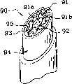
图15表示一个端片90,其具有一个接收格栅91的支撑件,所述格栅91具有一个中心部分91a和一个周边部分91b。Figure 15 shows an
周边部分91b直到其径向外边缘92具有短纤维敷层,该边缘与支撑件94的无短纤维边缘93接触。The
周边部分91b具有包围中心部分91a的波动起伏边缘95。The
图16表示具有一个支撑件101和一个配合件102的端片100,所述配合件具有一个中心部分102a和一个周边部分102b,它们通过材料桥102c相互连接。Figure 16 shows an
支撑件101具有管状裙边103,其顶部边缘104呈现波动起伏形状。The
配合件102也具有一个管状裙边105,其底部边缘106呈现出的形状与边缘104的形状互补,以致两个边缘104和106相互之间充分接触,如图16所示。Fitting
配合件102在其前表面108和侧表面109都具有短纤维敷层。The fitting 102 has a staple fiber coating on both its
所述短纤维敷层一直延伸直到边缘106与支撑件的无短纤维边缘104接触。边缘106是所述配合件的一个自由边缘。The staple fiber blanket extends until the
可以观察到由于短纤维裙边105压靠在支撑部分的边缘104上,所以能够获得呈现明显清晰外轮廓的短纤维敷层,不需要以面罩覆盖裙边105。It can be observed that since the
端片还可以给出其它形状,端片侧表面不必是圆形对称的。The end piece can also be given other shapes, the side surfaces of the end piece need not be circularly symmetrical.
通过实施例的方式,图17表示一个端片110,其具有一个支撑件111和一个配合件112,配合件112包括一个底部112a和一个偏移部分112b,所述底部与支撑件111接触,所述偏移部分相对于支撑件111的轴线偏心。By way of example, FIG. 17 shows an end piece 110 having a support member 111 and a mating member 112 comprising a base 112a and an offset portion 112b, said base being in contact with the support member 111 so that The offset portion is eccentric with respect to the axis of the support member 111 .
配合件112具有一个形成斜切面的顶面113。配合件112的整个外表面具有短纤维敷层。The mating part 112 has a top surface 113 forming a chamfer. The entire outer surface of the fitting 112 has a staple fiber coating.
短纤维敷层延伸到支撑件111的无短纤维的顶部边缘。The staple fiber blanket extends to the staple free top edge of the support 111 .
物质可以被包装起来,涂抹器表面可被以各种不同的其它方式供应所述物质。The substance may be packaged and the applicator surface may be supplied with the substance in a variety of other ways.
这样,图1所示的活塞和驱动旋钮容器可以被一个具有可变形壁的容器代替,如图18所示。Thus, the piston and drive knob receptacle shown in FIG. 1 can be replaced by a receptacle having deformable walls, as shown in FIG. 18 .
图18表示一个包装和涂抹器装置120,该装置包括一个与上述端片11相同的端片121,和一个由可压缩管122构成的容器。FIG. 18 shows a packaging and
在该实施例中,端片121的基部与管整体形成,但是在一个变换实施例中,基部本身可以由一个配合于所述管的件制成。In this embodiment the base of the
如图19所示,也可以采用一个泵给涂抹器表面供应物质。As shown in Figure 19, a pump may also be used to supply the substance to the applicator surface.
在该图中,可以看到一个装置130包括一个本体134,带有一个格栅132的端片131置于所述本体之上,格栅132类似于参照图8到图10描述的格栅42,该格栅包括一个环形沟槽153和一个固定在本体134上的支撑件133。In this figure, a
打开本体134的底端135,接收容纳一个再装品136,所述再装品包括一个盛装物质的容器137和带有一个空心控制杆139的泵138。The
驱使杆139进入位于本体134顶部的壳体140中。The
所述壳体140包括一个开通进入支撑件133中的壳体142底部的通道141,在所述支撑件壳体中固定格栅132。The housing 140 includes a
当泵138静止时,再装品136凸伸出本体134底部外。The
通过按压容器137的底部144,使用者向着本体134的顶部145推动再装品136,由此启动杆139并使得大量物质被分配。By depressing the bottom 144 of the
物质离开杆139的顶端,以类似于参照图8到图10描述的方式供应到涂抹器表面。The substance exits the tip of the
有益地,如图20所示,装置130具有一个关闭帽151,该关闭帽适合于例如通过按扣配合以密封方式固定在本体134上,并且包括一个底部裙边148,底部裙边148的底缘150适合于啮合在环形槽153中,以防止任何物质从中逸出,便于防止可能出现在格栅132底部和沟槽153中的物质与周围空气接触。Advantageously, as shown in FIG. 20, the
如图21所示,也可以使得端片的格栅具有向外凸出的外表面,或者如图22所示,向外凹进的外表面。As shown in FIG. 21 , it is also possible to make the grid of the end piece have an outwardly convex outer surface, or as shown in FIG. 22 , an outwardly concave outer surface.
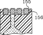
如图23所示,也可以使得端片的格栅被短纤维完全覆盖。As shown in Figure 23, it is also possible to have the grid of the end piece completely covered by short fibers.
在该图中,可以看到短纤维敷层延伸过端片的外表面直到格栅顶部周边155为止,所述周边大体上与接收格栅的支撑件的相应的无短纤维的边缘156接触。In this figure, it can be seen that the staple fiber blanket extends over the outer surface of the end piece up to the grid
尽管优选用于涂抹物质的表面是一个斜切面,以便易于涂抹物质而获得整洁优雅的化妆,但是涂抹器表面垂直于支撑件的轴线延伸并没有超出本发明的范围,如图23所示。It is not outside the scope of the invention for the applicator surface to extend perpendicular to the axis of the support, although it is preferred that the surface for applying the substance is a chamfered surface for ease of application of the substance for a clean and elegant finish, as shown in FIG. 23 .
进一步,尽管物质优先到达涂抹器表面的沟槽或空腔的一个限定区域也是优选的(通常就是这样),但是物质以均匀的方式到达涂抹器表面并没有超出本发明的范围。Further, it is not beyond the scope of the invention for the substance to reach the applicator surface in a uniform manner, although preferential access of the substance to a defined area of the groove or cavity of the applicator surface is also preferred (and usually is).
图24表示一个端片160,该端片包括一个带有中心区域163a的格栅163。Figure 24 shows an
涂抹器表面161垂直于端片轴线延伸,物质以均匀的方式到达涂抹器表面161,由于所述表面通过开通进入接收格栅163的壳体中心的通道162被供应,该格栅具有完全相同的通道164,这些通道围绕中心区域163a形成。The
在不超出本发明范围的前提下,支撑件和格栅可以以许多种方式制造。The supports and grids can be manufactured in many ways without exceeding the scope of the invention.
特别是,喷嘴导流板可以与支撑件整体形成。In particular, the nozzle deflector may be integrally formed with the support.
通过实施例的方式,图25表示一个端片170,其具有一个支撑件171和一个固定在支撑件上的格栅172。By way of example, FIG. 25 shows an
支撑件171具有给格栅172供应物质的通道173。The
喷嘴导流板174与支撑件171整体形成。The
在这一实施例中,可以看到格栅172的周边缘向下延伸有一个固定裙边175,该裙边以不泄露方式按扣配合于在支撑件171上形成的一个轮缘176上。In this embodiment, it can be seen that the perimeter edge of the
所述轮缘本身从支撑件171的侧面177向回退。The rim itself is set back from the
裙边175的外表面覆盖有短纤维敷层178,其延伸到与无短纤维敷层的支撑件171的相应边缘180接触的底缘179,所述边缘由其中的台阶确定。The outer surface of the
可以观察到由裙边175上的短纤维敷层的硬毛自由端确定的包封表面S平行于端片的轴Y,并且和支撑件171侧面大体上一致。It can be observed that the envelope surface S defined by the free ends of the bristles of the staple fiber coating on the
如图26所示,也可以用没有短纤维的格栅制造所述端片,或者用仅在其外表面的一部分上有短纤维的格栅制造所述端片。As shown in Figure 26, the end piece can also be made from a grid without short fibers, or from a grid with short fibers on only a portion of its outer surface.
该图表示出一个带有支撑件191的端片190,所述支撑件在顶部包括一个外部裙边192,所述裙边确定了一个接收格栅194的壳体193。The figure shows an
格栅194具有一个中心部分194a和一个周边部分194b,它们通过一个材料桥194c相互连接起来。The
中心部分194a的外侧面覆盖有短纤维敷层。The outer side of the
周边部分194b没有覆盖短纤维。The
裙边192的顶端覆盖有短纤维敷层197,其与格栅194的没有短纤维敷层的周边部分194b相接触。The top end of the
在所示的实施例中,格栅194通过开通的与中心部分194a中间对齐的通道196供应物质。In the illustrated embodiment, the
在没有表示出的一种变形中,格栅通过偏心的一个通道供应物质,以便使得物质优先在涂抹器表面的预定区域被排出。In a variant not shown, the grid supplies the substance through an eccentric channel so that the substance is preferentially expelled in a predetermined area of the applicator surface.
图27表示一个端片200,该端片包括一个支撑件201和一个配合于其中的格栅202。Figure 27 shows an
所述格栅200具有一个中心部分202a,其底面出现一个适合于关闭通道204的闸门形成突起203,所述通道204用于给格栅202供应物质。The
中心部分202a通过材料桥202c与周边部分202b连接。The
周边部分202b延伸到一个边缘202d,该边缘与支撑件201的侧面205相一致。The
格栅202在其前面并向外一直到边缘202d都覆盖有短纤维敷层。The
侧面205没有短纤维敷层。
图28表示一个端片210,其具有一个支撑件211和一个配合部分212,所述支撑件211例如与容器形成本体215整体而成。FIG. 28 shows an
支撑件211具有一个由一颈部214确定的中心通道213,所述颈部形成一个凸肩216并在此与本体215连接。The
喷嘴导流板217被整体铸造在支撑件顶部。The
喷嘴导流板217关闭通道213的大部分截面并确定了颈部214内物质的通道219。
配合部分212呈套筒形式,其外侧面222和前表面223都覆盖有短纤维敷层。The
短纤维敷层也出现于在前表面223和颈部214的顶端225之间延伸的内侧表面224部分上,配合件212的高度大于颈部214的高度。The staple fiber blanket is also present on the portion of the
侧面222位置与没有短纤维覆盖的本体215的外侧表面227相一致。The
图29表示一个分配端片230,其具有一个支撑件231和固定在其上的一个格栅232。Figure 29 shows a dispensing
格栅232具有一个固定在支撑件231上的周边部分232a,和一个通过材料桥232c连接到周边部分232a的环形部分232b。The
喷嘴导流板232d被制造在环形部分232b的中间位置,与通道235对齐,物质通过所述通道被供应到格栅。A
喷嘴导流板232d通过材料桥232e被连接到所述环形部分232b。The
支撑件231具有确定一接收格栅232的壳体的裙边236,加热时通过镦锻裙边236的顶端而将格栅保持在支撑件231上。The
覆盖格栅232的短纤维敷层239延伸到从格栅232的边缘232f后退的一条线239a。该条线239a位于大体上与没有短纤维的裙边236的自由端236a对准的位置。The
可以看到由格栅232上的短纤维敷层的硬毛的自由端确定的包封表面S大体上与裙边236向下折叠部分的外表面236b相一致。It can be seen that the envelope surface S defined by the free ends of the bristles of the staple fiber blanket on the
当然,本发明不局限于上面描述的实施例。Of course, the present invention is not limited to the embodiments described above.
特别是,在不超出本发明范围的前提下,基部或支撑件的形状和配合件或格栅的形状可被进一步修改。In particular, the shape of the base or support and the shape of the fitting or grille may be further modified without going beyond the scope of the invention.
特别是,上面描述的实施例的各种特征可以相互结合。In particular, various features of the embodiments described above can be combined with each other.
端片的第二部分例如可以由短纤维泡沫材料制成。The second part of the end piece may for example be made of staple fiber foam.
Claims (39)
Applications Claiming Priority (2)
| Application Number | Priority Date | Filing Date | Title |
|---|---|---|---|
| FR0008309 | 2000-06-28 | ||
| FR0008309A FR2810858B1 (en) | 2000-06-28 | 2000-06-28 | DISTRIBUTION TIP COMPRISING TWO ASSEMBLED PARTS AND A FLOCKING COATING |
Publications (2)
| Publication Number | Publication Date |
|---|---|
| CN1330902A true CN1330902A (en) | 2002-01-16 |
| CN1209991C CN1209991C (en) | 2005-07-13 |
Family
ID=8851793
Family Applications (1)
| Application Number | Title | Priority Date | Filing Date |
|---|---|---|---|
| CNB011296887A Expired - Fee Related CN1209991C (en) | 2000-06-28 | 2001-06-28 | Dispenser end sheet including integrally associated portions and short fiber dressing |
Country Status (12)
| Country | Link |
|---|---|
| US (1) | US6745781B2 (en) |
| EP (1) | EP1169939B1 (en) |
| JP (1) | JP3895564B2 (en) |
| CN (1) | CN1209991C (en) |
| AR (1) | AR028764A1 (en) |
| AT (1) | ATE347829T1 (en) |
| BR (1) | BR0102540A (en) |
| CA (1) | CA2351803C (en) |
| DE (1) | DE60125101T2 (en) |
| ES (1) | ES2276756T3 (en) |
| FR (1) | FR2810858B1 (en) |
| MX (1) | MXPA01006651A (en) |
Families Citing this family (50)
| Publication number | Priority date | Publication date | Assignee | Title |
|---|---|---|---|---|
| ES2241945T3 (en) * | 2002-12-02 | 2005-11-01 | SCHWAN-STABILO COSMETICS GMBH & CO. KG | MANUFACTURING PROCEDURE FOR FLOCATED APPLICATIONS AND CORRESPONDING DEVICE. |
| US7309184B2 (en) * | 2003-08-15 | 2007-12-18 | Revlon Consumer Products Corporation | Dispenser for fluid materials |
| US20050054967A1 (en) * | 2003-09-05 | 2005-03-10 | Gary Ashe | Fome swab applicator for fluid-containing ampule |
| FR2860960B1 (en) * | 2003-10-17 | 2007-03-30 | Oreal | APPLICATOR OF A PRODUCT, IN PARTICULAR COSMETIC |
| ITMI20030584U1 (en) * | 2003-12-12 | 2005-06-13 | Intercos Italiana | APPLICABLE DEVICE FOR COSMETIC PRODUCTS |
| FR2868669B1 (en) * | 2004-04-09 | 2007-07-20 | Oreal | DEVICE FOR PACKAGING AND APPLYING A PRODUCT. |
| DE202004008901U1 (en) * | 2004-06-04 | 2005-10-13 | Schwan-Stabilo Cosmetics Gmbh & Co. Kg | applicator |
| FR2871664B1 (en) * | 2004-06-17 | 2006-07-28 | Techpack Int Sa | LIP RED APPLICATOR AND DISPENSER COMPRISING SAID APPLICATOR |
| WO2006037112A2 (en) | 2004-09-27 | 2006-04-06 | Medical Instill Technologies, Inc. | Laterally-actuated dispenser with one- way valve for storing and dispensing metered amounts of substances |
| USD543469S1 (en) | 2004-09-27 | 2007-05-29 | Medical Instill Technologies, Inc. | Tube dispenser |
| FR2879084B1 (en) | 2004-12-10 | 2007-04-06 | Oreal | DEVICE FOR PACKAGING AND APPLYING A COSMETIC PRODUCT |
| US8157467B2 (en) * | 2005-03-21 | 2012-04-17 | Johnson & Johnson Consumer Companies, Inc. | Device for administering fluid compositions including tensioning polymers |
| US20070086833A1 (en) * | 2005-10-19 | 2007-04-19 | Paul Gurrisi | Dispenser for personal care composition |
| FR2894941B1 (en) * | 2005-12-16 | 2008-02-01 | Cebal Sas Soc Par Actions Simp | DISTRIBUTOR APPLICATOR OF LOW VISCOUS PRODUCTS |
| USD579786S1 (en) | 2005-12-22 | 2008-11-04 | Medical Instill Technologies, Inc. | Dispenser |
| USD574232S1 (en) | 2006-02-09 | 2008-08-05 | Medical Instill Technologies, Inc. | Dispenser with laterally-actuated dispensing valve |
| USD580785S1 (en) | 2006-02-13 | 2008-11-18 | Medical Instill Technologies, Inc. | Dispenser |
| US8215861B2 (en) * | 2006-02-15 | 2012-07-10 | L'oreal | Packaging and applicator device |
| FR2897245B1 (en) | 2006-02-15 | 2008-04-25 | Oreal | DEVICE FOR CONDITIONING AND APPLICATION. |
| FR2899076B1 (en) * | 2006-04-03 | 2008-07-04 | Oreal | PACKAGING AND APPLICATION DEVICE |
| US8297869B2 (en) * | 2006-04-03 | 2012-10-30 | L'oreal | Packaging and applicator device |
| JP5149499B2 (en) * | 2006-09-15 | 2013-02-20 | 株式会社壽 | Application container |
| WO2008061041A2 (en) * | 2006-11-11 | 2008-05-22 | Medical Instill Technologies, Inc. | Multiple dose delivery device with manually depressible actuator and one-way valve for storing and dispensing substances, and related method |
| US7785026B2 (en) * | 2007-01-08 | 2010-08-31 | Serena Eng | Cosmetic applicator device |
| DE102007022255B4 (en) * | 2007-05-09 | 2009-07-09 | Beiersdorf Ag | Release plate for optically attractive antiperspirant formulations |
| BR112012005250A2 (en) | 2009-09-16 | 2019-09-24 | Colgate Palmolive Co | oral care system, combined oral care dispenser and toothbrush, and methods for applying oral care material to an oral surface and teeth |
| US8360673B2 (en) * | 2009-10-14 | 2013-01-29 | Walter Dwyer | Dual-reservoir mascara applicator with dispersive product delivery |
| US8801315B2 (en) | 2009-10-14 | 2014-08-12 | Cosmopak Usa, Llc | Airless cosmetics applicator with airtight sealing dual cap |
| CN102711554B (en) | 2009-12-23 | 2014-10-29 | 高露洁-棕榄公司 | Oral care system |
| PH12012500882A1 (en) | 2009-12-23 | 2013-01-07 | Colgate Palmolive Co | Oral care system, kit and method |
| KR101528395B1 (en) | 2009-12-23 | 2015-06-11 | 콜게이트-파아므올리브캄파니 | Oral care system |
| KR101513342B1 (en) | 2009-12-23 | 2015-04-17 | 콜게이트-파아므올리브캄파니 | Oral care system |
| JP2011219118A (en) * | 2010-04-07 | 2011-11-04 | Kao Corp | Cap for liquid vessel |
| JP2011218046A (en) * | 2010-04-13 | 2011-11-04 | Asanuma Corporation | Cosmetic storage container |
| US20130245597A1 (en) | 2010-11-19 | 2013-09-19 | Robert C. Johnson | Click pen applicator device and method of using same |
| BR112013014928B1 (en) | 2010-12-15 | 2020-12-15 | Colgate - Palmolive Company | ORAL HYGIENE DISTRIBUTOR AND SYSTEM |
| DE102011007405A1 (en) * | 2011-04-14 | 2012-10-18 | Ing. Erich Pfeiffer Gmbh | Cosmetic dispenser |
| CN102203705B (en) * | 2011-06-10 | 2015-04-08 | 华为终端有限公司 | A touch-off method and wireless hand-held device |
| US20140001071A1 (en) * | 2012-06-29 | 2014-01-02 | Michael David Sanders | Package for laundry detergent having apparent pre-treat capability |
| US20140048562A1 (en) * | 2012-08-17 | 2014-02-20 | Meadwestvaco Corporation | Pump device and flow control system |
| US8757914B1 (en) * | 2013-03-15 | 2014-06-24 | BlokRok, Inc. | Apparatus and method for dispensing a fluid |
| US9498042B2 (en) * | 2013-06-24 | 2016-11-22 | HCT Group Holdings Limited | Dispenser with spaced thermal member |
| BR102014016689B1 (en) | 2014-07-04 | 2021-12-28 | Eric Zembrod | VALVE MECHANISM WITH APPLICATOR TIP FOR COSMETIC PACKAGING |
| EP3244772B1 (en) | 2015-02-02 | 2023-07-26 | Colgate-Palmolive Company | Oral care material dispenser |
| US10285485B2 (en) | 2016-03-25 | 2019-05-14 | Blok Rok, Inc. | Apparatus and method for dispensing fluid |
| US10092077B1 (en) * | 2017-04-11 | 2018-10-09 | Ojip, Llc | Device for applying and removing nail polish |
| WO2019237162A1 (en) | 2018-06-12 | 2019-12-19 | Eric Zembrod | Airless dispensing device for applicator tips for a range of flexible packagings |
| US11382400B2 (en) | 2018-08-10 | 2022-07-12 | Go Products Co. | Material applicator |
| US11224277B2 (en) * | 2018-12-04 | 2022-01-18 | Mimma Ganci | Two-sided applicator assembly |
| CN223438043U (en) * | 2024-10-22 | 2025-10-17 | 洽兴包装工业(中国)有限公司 | Application component, pen head component and coating material dispenser containing the application component |
Family Cites Families (21)
| Publication number | Priority date | Publication date | Assignee | Title |
|---|---|---|---|---|
| US3179972A (en) | 1963-06-10 | 1965-04-27 | Owens Illinois Glass Co | Liquid applicators |
| US3807881A (en) | 1972-08-03 | 1974-04-30 | Menley & James Labor Ltd | Cosmetic applicator |
| US3825021A (en) | 1973-05-07 | 1974-07-23 | Applicator Brush Co Inc | Cosmetic applicator |
| US4368746A (en) | 1981-06-01 | 1983-01-18 | Spatz Steven D | Valved cosmetic applicator |
| KR870009681A (en) | 1986-04-28 | 1987-11-30 | 리챠드 제이. 롤즈호센 | Liquid cosmetic containers with floc fiber cladding |
| US4772148A (en) | 1986-05-30 | 1988-09-20 | Buschemeyer Sallie Q | Liquid applicator |
| US4902155A (en) | 1988-07-21 | 1990-02-20 | Buschemeyer Sallie Q | Liquid dispenser |
| FR2642675B1 (en) * | 1989-02-07 | 1991-05-03 | Oreal | DISPENSER FOR PASTE OR SOLID PRODUCT COMPRISING A COATING OF ITS DISPENSING PORT |
| US5199808A (en) * | 1989-11-30 | 1993-04-06 | L'oreal | Device for application of a liquid or pasty product to a surface |
| DE9407891U1 (en) * | 1994-05-16 | 1995-09-14 | Bramlage GmbH, 49393 Lohne | lipstick |
| US5908256A (en) | 1994-10-07 | 1999-06-01 | Bernstein; Melvin | Bottle with built-in telescoping applicator head and valve therein |
| FR2727608B1 (en) | 1994-12-06 | 1997-01-10 | Oreal | DISPENSER FOR A LIQUID CONSISTENCY PRODUCT WITH PASTE |
| FR2731681B1 (en) * | 1995-03-17 | 1997-04-30 | Oreal | APPLICATOR FOR PRODUCT OF VISCOUS CONSISTENCY, COMPRISING A POROUS DISTRIBUTION ORGAN |
| US5797692A (en) | 1995-08-30 | 1998-08-25 | Poole; Daniel L. | Apparatus and method for dispensing and spreading flowable material upon a surface |
| FR2752149B1 (en) * | 1996-08-08 | 1998-10-16 | Oreal | DEVICE FOR MAKING LIPS |
| US5851079A (en) * | 1996-10-25 | 1998-12-22 | The Procter & Gamble Company | Simplified undirectional twist-up dispensing device with incremental dosing |
| US6099184A (en) | 1997-05-14 | 2000-08-08 | Painter's Products, Inc. | Dispenser-applicator assembly |
| FR2773959B1 (en) * | 1998-01-26 | 2000-04-07 | Oreal | PACKAGING AND APPLICATION ASSEMBLY OF A POWDERY, LIQUID OR PASTY PRODUCT COMPRISING A PISTON |
| DE19858410A1 (en) | 1998-12-17 | 2000-06-29 | Schwan Stabilo Cosmetics Gmbh | Application device |
| FR2792296B1 (en) | 1999-04-16 | 2001-06-01 | Oreal | APPLICATOR CAPSULE AND APPLICATION ASSEMBLY PROVIDED WITH SUCH APPLICATOR CAPSULE |
| CA2313069C (en) * | 1999-07-01 | 2006-05-09 | Filtertek Inc. | Semisolid product dispensing head |
-
2000
- 2000-06-28 FR FR0008309A patent/FR2810858B1/en not_active Expired - Fee Related
-
2001
- 2001-06-18 US US09/884,178 patent/US6745781B2/en not_active Expired - Lifetime
- 2001-06-22 JP JP2001226791A patent/JP3895564B2/en not_active Expired - Fee Related
- 2001-06-26 DE DE60125101T patent/DE60125101T2/en not_active Expired - Lifetime
- 2001-06-26 AT AT01401687T patent/ATE347829T1/en not_active IP Right Cessation
- 2001-06-26 EP EP01401687A patent/EP1169939B1/en not_active Expired - Lifetime
- 2001-06-26 ES ES01401687T patent/ES2276756T3/en not_active Expired - Lifetime
- 2001-06-27 MX MXPA01006651A patent/MXPA01006651A/en active IP Right Grant
- 2001-06-27 BR BR0102540-6A patent/BR0102540A/en not_active Application Discontinuation
- 2001-06-27 CA CA002351803A patent/CA2351803C/en not_active Expired - Fee Related
- 2001-06-28 AR ARP010103076A patent/AR028764A1/en not_active Application Discontinuation
- 2001-06-28 CN CNB011296887A patent/CN1209991C/en not_active Expired - Fee Related
Also Published As
| Publication number | Publication date |
|---|---|
| DE60125101T2 (en) | 2007-07-12 |
| AR028764A1 (en) | 2003-05-21 |
| US6745781B2 (en) | 2004-06-08 |
| EP1169939A1 (en) | 2002-01-09 |
| ES2276756T3 (en) | 2007-07-01 |
| MXPA01006651A (en) | 2004-07-30 |
| DE60125101D1 (en) | 2007-01-25 |
| ATE347829T1 (en) | 2007-01-15 |
| CN1209991C (en) | 2005-07-13 |
| US20020007839A1 (en) | 2002-01-24 |
| FR2810858B1 (en) | 2003-01-10 |
| CA2351803A1 (en) | 2001-12-28 |
| JP3895564B2 (en) | 2007-03-22 |
| CA2351803C (en) | 2005-09-06 |
| EP1169939B1 (en) | 2006-12-13 |
| JP2002125752A (en) | 2002-05-08 |
| FR2810858A1 (en) | 2002-01-04 |
| BR0102540A (en) | 2002-02-05 |
Similar Documents
| Publication | Publication Date | Title |
|---|---|---|
| CN1330902A (en) | Dispenser end sheet including integrally associated portions and short fiber dressing | |
| CN1164459C (en) | Packaging and applicator unit with an applicator area for a specific supply method | |
| CN1868368A (en) | Storing and applying device | |
| CN1101165C (en) | Packaging and application device, and reloading element therefor | |
| CN1216772C (en) | Container installed with sucking tube and coating element | |
| CN1946615A (en) | Application content extrusion container | |
| CN1251935C (en) | Applying device, system and method | |
| CN1673049A (en) | Assembly for packaging and dispensing liquid | |
| CN1344664A (en) | Packing and painting device including paint piece | |
| CN1671603A (en) | Reverse-flow prevention plug for container, the container, and pouring device | |
| CN1245125C (en) | Applicators and packaging and application devices for applying cosmetic or care products to eyelashes or eyebrows | |
| CN1093828C (en) | Simplified unidirectional twist-up dispensing device with continuous dosing | |
| CN105708109B (en) | Cosmetics containers | |
| CN1254419C (en) | Assembly for packing and distributing product, especially using sample form | |
| CN1644130A (en) | Device for applying a product | |
| CN1868371A (en) | Applicator for applying a composition to the eyelashes and/or the eyebrows | |
| CN1293949C (en) | Accumulator Liquid Ejector | |
| CN1410325A (en) | Device for packing substance, in particular, cosmetics or curing article | |
| CN1426281A (en) | hair styling device | |
| CN1747793A (en) | Improvements in or relating to nozzle arrangements | |
| CN1891101A (en) | Applicator, a packaging and applicator device including such an applicator, a method of manufacturing such an applicator, and a machine for manufacturing such an applicator | |
| CN1290641A (en) | packaging and painting unit | |
| CN1868370A (en) | Applicator and a device for applying a cosmetic | |
| CN1871163A (en) | Fluid dispensing components | |
| CN1968621A (en) | Tooth brush |
Legal Events
| Date | Code | Title | Description |
|---|---|---|---|
| C10 | Entry into substantive examination | ||
| SE01 | Entry into force of request for substantive examination | ||
| C06 | Publication | ||
| PB01 | Publication | ||
| C14 | Grant of patent or utility model | ||
| GR01 | Patent grant | ||
| C17 | Cessation of patent right | ||
| CF01 | Termination of patent right due to non-payment of annual fee |
Granted publication date: 20050713 |