CN1343177A - Device for dispensing adhesive tape in strips - Google Patents
Device for dispensing adhesive tape in strips Download PDFInfo
- Publication number
- CN1343177A CN1343177A CN00804916.5A CN00804916A CN1343177A CN 1343177 A CN1343177 A CN 1343177A CN 00804916 A CN00804916 A CN 00804916A CN 1343177 A CN1343177 A CN 1343177A
- Authority
- CN
- China
- Prior art keywords
- handle
- conveying roller
- gear
- described device
- lever
- Prior art date
- Legal status (The legal status is an assumption and is not a legal conclusion. Google has not performed a legal analysis and makes no representation as to the accuracy of the status listed.)
- Granted
Links
Images


Classifications
-
- B—PERFORMING OPERATIONS; TRANSPORTING
- B65—CONVEYING; PACKING; STORING; HANDLING THIN OR FILAMENTARY MATERIAL
- B65H—HANDLING THIN OR FILAMENTARY MATERIAL, e.g. SHEETS, WEBS, CABLES
- B65H35/00—Delivering articles from cutting or line-perforating machines; Article or web delivery apparatus incorporating cutting or line-perforating devices, e.g. adhesive tape dispensers
- B65H35/0006—Article or web delivery apparatus incorporating cutting or line-perforating devices
- B65H35/002—Hand-held or table apparatus
- B65H35/0026—Hand-held or table apparatus for delivering pressure-sensitive adhesive tape
-
- B—PERFORMING OPERATIONS; TRANSPORTING
- B65—CONVEYING; PACKING; STORING; HANDLING THIN OR FILAMENTARY MATERIAL
- B65H—HANDLING THIN OR FILAMENTARY MATERIAL, e.g. SHEETS, WEBS, CABLES
- B65H35/00—Delivering articles from cutting or line-perforating machines; Article or web delivery apparatus incorporating cutting or line-perforating devices, e.g. adhesive tape dispensers
- B65H35/0006—Article or web delivery apparatus incorporating cutting or line-perforating devices
- B65H35/006—Article or web delivery apparatus incorporating cutting or line-perforating devices with means for delivering a predetermined length of tape
Landscapes
- Adhesive Tape Dispensing Devices (AREA)
- Package Closures (AREA)
- Auxiliary Devices For And Details Of Packaging Control (AREA)
Abstract
Description
本发明涉及一种以条带方式输出胶带等的装置,该装置具有一个胶带卷支座、至少一个具有环槽的输送辊和一个与输送辊配合的具有环形凸起的折曲辊、一个与手柄连接的对至少一个输送辊驱动的第一齿条、一个被与手柄连接的第二齿条通过第一齿轮释放的切割件。The present invention relates to a device for outputting adhesive tapes etc. in strips, the device has an adhesive tape roll support, at least one conveying roller with a ring groove and a bending roller with an annular protrusion cooperating with the conveying roller, a A first rack connected to the handle drives at least one conveying roller, and a second rack connected to the handle releases a cutting member through the first gear.
例如在US-A-5,207,860披露了这样一种装置。所述的装置具有一个手柄,该手柄至少具有两个弧形的齿条,所述齿条与不同的齿轮啮合。该装置由多个部件构成。手柄以可旋转的方式设置在一个轴上并通过销杆与齿条连接。利用一较为复杂的传动机构和不同的张力弹簧和簧片对切割件进行控制。由于齿条的一端枢设在手柄侧面,因而势必会产生作用于手柄轴上的微量的扭矩,从而在杠杆向下移动时并不能避免齿条被卡死。另外,上述装置的体积较大,因而造成在实践中不太易于使用。Such a device is disclosed, for example, in US-A-5,207,860. Said device has a handle with at least two arc-shaped racks, said racks meshing with different gears. The device consists of several components. The handle is rotatably arranged on a shaft and connected with the rack through a pin rod. The cutter is controlled by a relatively complex transmission mechanism and different tension springs and reeds. Since one end of the rack is pivotally arranged on the side of the handle, there will inevitably be a small amount of torque acting on the shaft of the handle, so that the rack cannot be prevented from being stuck when the lever moves downward. In addition, the aforementioned devices are relatively bulky and thus not very easy to use in practice.
本发明的目的在于提出一种以条带方式输出胶带的装置,该装置由非常少的部件制成并且非常易于操作。The object of the present invention is to propose a device for outputting adhesive tape in strips which is made of very few parts and which is very easy to handle.
实现该目的的技术方案是:一种以条带方式输出胶带等的装置,具有一个胶带卷支座、至少一个具有环槽的输送辊和一个与输送辊配合的具有环形凸起的折曲辊、一个与手柄连接的对至少一个输送辊驱动的第一齿条、一个被与手柄连接的第二齿条通过第一齿轮释放的切割件,其中两根齿条设置在手柄两侧,由一位于机壳下段的下摇杆和一在手柄上的上摇杆对至少一根齿条进行控制,在手柄向下移动时齿条间接地与输送辊啮合并与第一齿轮啮合,并且在手柄向上移动时脱离啮合。The technical solution to achieve this goal is: a device for outputting tapes in strips, which has a tape roll support, at least one conveying roller with an annular groove, and a bending roller with annular protrusions that cooperates with the conveying roller , a first rack connected to the handle to drive at least one conveying roller, a second rack connected to the handle to release the cutting member through the first gear, wherein two racks are arranged on both sides of the handle, and a A lower rocker located at the lower section of the casing and an upper rocker on the handle control at least one toothed rack, the toothed rack indirectly engages with the conveying roller and engages with the first gear when the handle moves downwards, and at the handle Disengages when moving up.
本发明的装置具有结构紧凑和特别易于操作等优点。另外胶带卷的支架为插卡件,因而可以继续使用胶带取用器的大部分的部件。The device according to the invention has the advantage of being compact and particularly easy to handle. In addition, the support for the tape roll is a card insert, so that most of the parts of the tape taker can continue to be used.
下面将对照示意图中示出的实施例对本发明做进一步的说明。图中示出:The invention will be further described below with reference to the embodiments shown in the schematic diagrams. The figure shows:
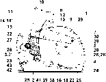
图1为手柄处在初始位置时的胶带取用器的原理图;Fig. 1 is the schematic diagram of the tape taker when the handle is in the initial position;
图2示出图1所示的相同的胶带取用器,但其手柄处于被向下按压的状态;Figure 2 shows the same tape dispenser as shown in Figure 1, but with its handle pressed down;
图3示出胶带取用器的输送机理;Fig. 3 shows the delivery mechanism of the tape taker;
图4为输送辊和折曲辊的俯视图和截面图;Fig. 4 is a top view and a cross-sectional view of a conveying roller and a bending roller;
图5示出说明输送辊驱动过程的手柄的各种位置;和Figure 5 shows the various positions of the handle illustrating the delivery roller drive process; and
图6示出说明切割过程的手柄的各种位置。Figure 6 shows various positions of the handle illustrating the cutting process.
在附图中对相同的部件采用统一的附图标记。如果没有另外的明确的说明的话,则第一次的描述涉及所有的附图。In the figures, identical components are provided with uniform reference numbers. If not explicitly stated otherwise, the first description refers to all figures.
如图1和2所示,胶带取用器1具有一个带有两个相互基本平行设置的机壳壁3、3’的机壳3,从图中仅能看到前机壳壁3的轮廓4。另外,在两个机壳壁3、3’之间设置有一环围的连接件5。在两个机壳壁3、3’上设置有一个枢设在旋转轴7上的手柄8,该手柄由两个L-形型件9、9’(图中仅示出前型件9)和一个上连接件10构成。另外,手柄8在面向机壳2侧具有一个凸肩11,该凸肩用于对胶带条进行抓取。在两个L型件9上设置有一个销杆12,该销杆嵌入具有一扇形齿段15的三角形齿条14的短的第一摇杆13内。一销杆18固定在齿条14的下角16上,所述销杆嵌入一在机壳壁3上的较长的弧形的摇杆20上。在图中未示出的另一个相同的齿条14’设置在相对的机壳壁3’上。手柄8被一图中未详细示出的U形张紧弹簧保持在图1所示出的初始位置。一方面该张紧弹簧的一个腿抵压在L-型件9的下侧,另一方面其另一个腿设置在机壳壁3的凸起上。当然,为实现该目的也可以采用其它的诸如片簧、盘簧等压力弹簧。As shown in FIGS. 1 and 2, the
另外,在支架24上设置有两个输送辊22和23,所述支架由两个被间隔件25固定在一起的侧件26、26’构成。两个在轴向上刻有槽纹的输送辊22和23在每一侧具有一个齿轮27和28,所述齿轮可以与齿条14啮合。另外,多个起着轴作用的销杆29设置在两个侧件26、26’之间,胶带卷30旋转地设置在销杆上。销杆29同时起着间隔件和两个侧件26、26’之间的连接件的作用。支架24作为插卡件,因而在将胶带卷30用完后可以对支架进行调换。在相对的机壳壁3’上设置有一个带有作为切割件的三角形刀具33的略有弯曲的杠杆臂32。杠杆臂32的作为控制摇杆的下棱36抵靠在齿轮38的凸台37上,所述齿轮38同样枢设在的机壳壁3’的轴39上。在齿轮38的内侧上设置有一个销杆41,该销杆利用一张紧弹簧42被预拉紧在机壳壁3’的另一个销杆43上。当齿轮38与齿条14’脱离时(图1),张紧弹簧42回缩。当齿轮38被齿条14’旋转约180°时(图2),张紧弹簧42处于最大拉伸状态,当齿轮38与齿条14’脱离时,齿轮38重新返回其初始位置(图1)。In addition, two
图3中示出对胶带卷30的胶带(图中用虚线示出)的导向控制。其中,输送辊22和23通过其齿轮27和28被齿条14顺时针旋转,从而使胶带45通过位于两个输送辊22和23之间的折曲辊47被纵向折曲。其中,第二输送辊23具有两个环槽48(图4),因此在中间形成一个圆环49。第一输送辊22仅具有一个环槽51,该环槽与圆环49配合并略以重叠方式将后者覆盖。折曲辊47具有一个中间的环形凸起52,使胶带20在纵向上被折成V-形。在图3中可以清楚地看到支架24,该支架为可插入机壳2内的插卡件结构。The guide control of the adhesive tape (shown by the dotted line in the drawing) of the
图5中示出利用两个输送辊22和23的输送过程。在图5a中手柄8处于初始位置,即被压力弹簧向上压(箭头A)。其中,齿条14脱离两个输送辊22和23的齿轮27和28。由于手柄8的L形侧件9位于在图中被省略的机壳壁3附近,所以图中部分齿条14用虚线示出。当手柄8被向下按压时(图5b),齿条14被摇杆13和20置于与两个齿轮27和28啮合的状态,从而使输送辊22和23顺时针旋转并对胶带45进行输送。当手柄8被完全压向下方时,齿条14仍保持与齿轮27和28啮合。只有当手柄8被释放并被压力弹簧向上移动时,齿条14才与齿轮27和28脱离,即齿轮27和28停止转动并且不再输送胶带45。The conveying process with two
在手柄8由上(图5a)向下(图5c)移动时,则由输送辊22和23对精确定长的胶带或带条进行输送。而且也可以在中间位置(图5b)将手柄8释放,从而使齿条14与齿轮27和28脱离。当手柄8再次被向下按压时,将因此输送出较长的胶带。通过多次按压可得到任意长度的胶带。When the
在图6中详细地示出切割过程。与齿条14类似,此时的齿条14’被手柄8向下移动。如图中所示,齿条14’仅在下段具有齿,所述齿可以与齿轮38啮合。在最下面的位置(图6c),齿条14’的齿始终与齿轮38啮合,从而使张力弹簧42被完全拉紧。当此时将手柄8释放,则带有凸台37的齿轮38继续顺时针旋转并且带有三角形刀具33的杠杆臂32被向上弹起,从而使胶带45条被切割(图6d)。由于胶带45事先已被折曲辊47折成V形。所以在被切割的条带上形成直线切口。如果这时在中间位置(图6b)将手柄8释放,则杠杆臂32并不会被弹回,这是因为齿轮38和随之的凸台37又被旋回,从而造成条带未被切割。所以,通过输送辊22和23和未被驱动的刀具33的配合可以确定从最短的长度(一次按压)开始的条带的长度。与图5所述相同,齿条14’也可以在整个长度上都具有齿。另一方面,齿条14和14’也可以与L型件9和9’一体成型,其中可以省去销杆12和第一摇杆13。The cutting process is shown in detail in FIG. 6 . Similar to the
对于专业人员来说很显然,上述胶带取用器1仅由非常少的部件构成,因而大大地节省了材料并降低了成本。该胶带取用器1的另一优点是,对诸如具有手柄8和切割件33的机壳2等主要构件可以继续应用,而需要更换的仅是带有胶带卷30的插卡件或支架24。因而可进一步减少对环境造成的负担。另外对插卡件或支架24也可以再利用。It is obvious to a professional that the above-mentioned
附图标记对照表1 胶带取用器2 机壳3、3’ 机壳壁4 轮廓5 连接件7 旋转轴8 手柄9、9’ L型件10 上连接件11 凸肩12 销杆13 第一摇杆14、14’ 齿条15 扇形齿段16 下角18 销杆20 较长的弧形摇杆22 输送辊23 输送辊24 支架25 间隔件26、26’ 侧件27 侧齿轮28 侧齿轮29 轴30 胶带卷32 杠杆臂33 三角形刀具34 轴37 凸台38 齿轮39 轴41 销杆42 张力弹簧43 销杆45 胶带47 折曲辊48 环槽49 圆环51 环槽52 中间环形凸起Attachment Label Comparison Table 1 Gas
Claims (11)
Applications Claiming Priority (2)
| Application Number | Priority Date | Filing Date | Title |
|---|---|---|---|
| CH572/1999 | 1999-03-25 | ||
| CH57299 | 1999-03-25 |
Publications (2)
| Publication Number | Publication Date |
|---|---|
| CN1343177A true CN1343177A (en) | 2002-04-03 |
| CN1153727C CN1153727C (en) | 2004-06-16 |
Family
ID=4190116
Family Applications (1)
| Application Number | Title | Priority Date | Filing Date |
|---|---|---|---|
| CNB008049165A Expired - Fee Related CN1153727C (en) | 1999-03-25 | 2000-03-27 | Device for dispensing adhesive tape in strips |
Country Status (9)
| Country | Link |
|---|---|
| EP (1) | EP1165420B1 (en) |
| JP (1) | JP2002540042A (en) |
| CN (1) | CN1153727C (en) |
| AT (1) | ATE252046T1 (en) |
| AU (1) | AU3315500A (en) |
| BR (1) | BR0009283A (en) |
| DE (1) | DE50004074D1 (en) |
| ES (1) | ES2208287T3 (en) |
| WO (1) | WO2000058193A1 (en) |
Cited By (6)
| Publication number | Priority date | Publication date | Assignee | Title |
|---|---|---|---|---|
| WO2011085572A1 (en) * | 2010-01-15 | 2011-07-21 | 广州番禺通用文具制品厂有限公司 | Automatic gummed paper machine |
| CN103692822A (en) * | 2013-12-26 | 2014-04-02 | 广东乐普升文具有限公司 | Rotary extension mechanism applied to stationery and stationery with same |
| CN109484905A (en) * | 2018-10-08 | 2019-03-19 | 戴闻 | A kind of ring-shaped adhesive tape cutter |
| CN111039068A (en) * | 2019-11-29 | 2020-04-21 | 刘祖金 | Release paper separating device used during double faced adhesive tape |
| CN111689288A (en) * | 2020-06-29 | 2020-09-22 | 泉州市朗利工业设计有限公司 | High cutting mechanism for product packaging of security |
| CN115303868A (en) * | 2021-05-08 | 2022-11-08 | 青岛海尔特种电冰柜有限公司 | Handheld tape-stripping device |
Families Citing this family (1)
| Publication number | Priority date | Publication date | Assignee | Title |
|---|---|---|---|---|
| WO2006106478A1 (en) * | 2005-04-07 | 2006-10-12 | Ray Technology Group B.V. | Device for dispensing adhesive tape sections strip-by-strip |
Family Cites Families (4)
| Publication number | Priority date | Publication date | Assignee | Title |
|---|---|---|---|---|
| US1431575A (en) * | 1921-10-20 | 1922-10-10 | Emmert Mfg Company Inc | Tape-delivering machine |
| US2586835A (en) * | 1949-04-26 | 1952-02-26 | Johnson & Johnson | Strip material dispensing and applying device |
| IL78704A0 (en) * | 1985-05-14 | 1986-08-31 | Ruyter J A De | Cutting appliance designed particularly for medical dressings |
| NL9001733A (en) * | 1990-07-31 | 1992-02-17 | Pelikan Ag | ADHESIVE DEVICE FOR ADHESIVE BAND AND TRANSMISSION MECHANISM. |
-
2000
- 2000-03-27 AT AT00911161T patent/ATE252046T1/en not_active IP Right Cessation
- 2000-03-27 BR BR0009283-5A patent/BR0009283A/en active Search and Examination
- 2000-03-27 ES ES00911161T patent/ES2208287T3/en not_active Expired - Lifetime
- 2000-03-27 AU AU33155/00A patent/AU3315500A/en not_active Abandoned
- 2000-03-27 DE DE50004074T patent/DE50004074D1/en not_active Expired - Fee Related
- 2000-03-27 JP JP2000607907A patent/JP2002540042A/en not_active Abandoned
- 2000-03-27 EP EP00911161A patent/EP1165420B1/en not_active Expired - Lifetime
- 2000-03-27 CN CNB008049165A patent/CN1153727C/en not_active Expired - Fee Related
- 2000-03-27 WO PCT/IB2000/000350 patent/WO2000058193A1/en not_active Ceased
Cited By (7)
| Publication number | Priority date | Publication date | Assignee | Title |
|---|---|---|---|---|
| WO2011085572A1 (en) * | 2010-01-15 | 2011-07-21 | 广州番禺通用文具制品厂有限公司 | Automatic gummed paper machine |
| CN103692822A (en) * | 2013-12-26 | 2014-04-02 | 广东乐普升文具有限公司 | Rotary extension mechanism applied to stationery and stationery with same |
| CN103692822B (en) * | 2013-12-26 | 2015-09-02 | 广东乐普升文具有限公司 | A kind ofly be applied to the rotation telescoping mechanism in stationery and the stationery with this mechanism |
| CN109484905A (en) * | 2018-10-08 | 2019-03-19 | 戴闻 | A kind of ring-shaped adhesive tape cutter |
| CN111039068A (en) * | 2019-11-29 | 2020-04-21 | 刘祖金 | Release paper separating device used during double faced adhesive tape |
| CN111689288A (en) * | 2020-06-29 | 2020-09-22 | 泉州市朗利工业设计有限公司 | High cutting mechanism for product packaging of security |
| CN115303868A (en) * | 2021-05-08 | 2022-11-08 | 青岛海尔特种电冰柜有限公司 | Handheld tape-stripping device |
Also Published As
| Publication number | Publication date |
|---|---|
| ATE252046T1 (en) | 2003-11-15 |
| DE50004074D1 (en) | 2003-11-20 |
| EP1165420A1 (en) | 2002-01-02 |
| CN1153727C (en) | 2004-06-16 |
| WO2000058193A1 (en) | 2000-10-05 |
| AU3315500A (en) | 2000-10-16 |
| JP2002540042A (en) | 2002-11-26 |
| EP1165420B1 (en) | 2003-10-15 |
| ES2208287T3 (en) | 2004-06-16 |
| BR0009283A (en) | 2002-01-22 |
Similar Documents
| Publication | Publication Date | Title |
|---|---|---|
| CN1343177A (en) | Device for dispensing adhesive tape in strips | |
| CA1172209A (en) | Paper towel dispenser with rack and gear drive | |
| CN100548844C (en) | Adhesive tape dispenser | |
| CN111136141A (en) | A silver bracelet material automatic bending device | |
| EP2527278A1 (en) | Automatic device for dispensing adhesive tape | |
| AU707145B2 (en) | Dispenser for supplying pieces of paper | |
| KR100317742B1 (en) | Adhesive tape roll holder and adhesive tape cutting device | |
| WO2009106010A1 (en) | A dispensing method and device of roll paper operated by single hand | |
| CN101112918A (en) | Filament band bundling knot-tying mechanism | |
| US3369573A (en) | Tying apparatus | |
| GB2164891A (en) | Attaching tags to merchandise using fasteners | |
| US2582731A (en) | Stapling machine for applying labels | |
| US20210024323A1 (en) | Manual adhesive tape dispenser. | |
| CN112078856A (en) | Scroll painting packing device | |
| CN214216265U (en) | Tying device and bread packaging machine | |
| CN100537384C (en) | Double-faced adhesive tape dispenser | |
| CN2304533Y (en) | Hand bookbinding apparatus | |
| JP2750294B2 (en) | Bag presser for binding machine | |
| WO2009011469A1 (en) | Automatic bundle packing apparatus using bonding tape | |
| CN209320291U (en) | A kind of pipeline purging machine for LED light strip | |
| CN2334325Y (en) | Cutting Structure of Wet Wipe Dispenser | |
| JP3349824B2 (en) | Seedling transfer packing device of rush seedling cassette packing machine | |
| CN112296146A (en) | Special-shaped card bending device | |
| CN221949566U (en) | A movable cigarette retail counter capable of being pressed on an inclined surface | |
| CN114290623B (en) | Nail and chopstick automatic head cutting machine |
Legal Events
| Date | Code | Title | Description |
|---|---|---|---|
| C06 | Publication | ||
| PB01 | Publication | ||
| C10 | Entry into substantive examination | ||
| SE01 | Entry into force of request for substantive examination | ||
| C14 | Grant of patent or utility model | ||
| GR01 | Patent grant | ||
| ASS | Succession or assignment of patent right |
Owner name: HENKEL KGAA Free format text: FORMER OWNER: RAY TECHNOLOGY GROUP B.V. Effective date: 20040702 |
|
| C41 | Transfer of patent application or patent right or utility model | ||
| TR01 | Transfer of patent right |
Effective date of registration: 20040702 Address after: Dusseldorf Patentee after: Henkel AG & Co. KG Address before: Holland, Germany and South Shandong Patentee before: Ray Technology Group B.V. |
|
| C19 | Lapse of patent right due to non-payment of the annual fee | ||
| CF01 | Termination of patent right due to non-payment of annual fee |