CN1370657A - Detachable chuck - Google Patents
Detachable chuck Download PDFInfo
- Publication number
- CN1370657A CN1370657A CN02103287.4A CN02103287A CN1370657A CN 1370657 A CN1370657 A CN 1370657A CN 02103287 A CN02103287 A CN 02103287A CN 1370657 A CN1370657 A CN 1370657A
- Authority
- CN
- China
- Prior art keywords
- main shaft
- stay
- lining
- cavity
- spring
- Prior art date
- Legal status (The legal status is an assumption and is not a legal conclusion. Google has not performed a legal analysis and makes no representation as to the accuracy of the status listed.)
- Pending
Links
Images





Classifications
-
- B—PERFORMING OPERATIONS; TRANSPORTING
- B23—MACHINE TOOLS; METAL-WORKING NOT OTHERWISE PROVIDED FOR
- B23Q—DETAILS, COMPONENTS, OR ACCESSORIES FOR MACHINE TOOLS, e.g. ARRANGEMENTS FOR COPYING OR CONTROLLING; MACHINE TOOLS IN GENERAL CHARACTERISED BY THE CONSTRUCTION OF PARTICULAR DETAILS OR COMPONENTS; COMBINATIONS OR ASSOCIATIONS OF METAL-WORKING MACHINES, NOT DIRECTED TO A PARTICULAR RESULT
- B23Q3/00—Devices holding, supporting, or positioning work or tools, of a kind normally removable from the machine
- B23Q3/12—Devices holding, supporting, or positioning work or tools, of a kind normally removable from the machine for securing to a spindle in general
-
- B—PERFORMING OPERATIONS; TRANSPORTING
- B25—HAND TOOLS; PORTABLE POWER-DRIVEN TOOLS; MANIPULATORS
- B25B—TOOLS OR BENCH DEVICES NOT OTHERWISE PROVIDED FOR, FOR FASTENING, CONNECTING, DISENGAGING, OR HOLDING
- B25B23/00—Details of, or accessories for, spanners, wrenches, screwdrivers
- B25B23/0007—Connections or joints between tool parts
- B25B23/0035—Connection means between socket or screwdriver bit and tool
-
- B—PERFORMING OPERATIONS; TRANSPORTING
- B25—HAND TOOLS; PORTABLE POWER-DRIVEN TOOLS; MANIPULATORS
- B25F—COMBINATION OR MULTI-PURPOSE TOOLS NOT OTHERWISE PROVIDED FOR; DETAILS OR COMPONENTS OF PORTABLE POWER-DRIVEN TOOLS NOT PARTICULARLY RELATED TO THE OPERATIONS PERFORMED AND NOT OTHERWISE PROVIDED FOR
- B25F3/00—Associations of tools for different working operations with one portable power-drive means; Adapters therefor
Landscapes
- Engineering & Computer Science (AREA)
- Mechanical Engineering (AREA)
- Gripping On Spindles (AREA)
- Automatic Tool Replacement In Machine Tools (AREA)
- Jigs For Machine Tools (AREA)
- Details Of Rigid Or Semi-Rigid Containers (AREA)
Abstract
A removable chuck has a chuck member for holding a drill bit. Also, a mechanism is coupled with the chuck body to retain the chuck body to a drill spindle. The retention mechanism, in a first position, has at least one biased blade, in a nonbiased condition, retaining the chuck on the drill spindle and in a second position, with the at least one biased blade in a biased condition, the chuck is enabled to be removed from the spindle.
Description
Quoting of related application
This application is that the application number that proposes February 14 calendar year 2001 is the continuation of partial content of the U.S. Patent application of NO.09/782812; And the application number application number that to be the application of NO.09/782812 be proposed on June 19th, 2000 is the continuation of partial content of the U.S. Patent application of NO.09/596762; And application number be the application of NO.09/596762 is that the application number that proposed on October 6th, 1998 is NO.09/167305, and is the continuation of United States Patent (USP) NO.6079716 in approval on June 27th, 2000; And this United States Patent (USP) NO.6079716 is that the application number that proposed on December 12nd, 1997 is NO.08/989715, and on September 14th, 1999 approval continuation for the partial content of United States Patent (USP) NO.5951026, the specification of each application and accompanying drawing all in this application as a reference.
Technical field
The present invention relates to such as drilling machine percussion drill, the rotatable instrument of screwdriver and other power tools and so on.Specifically, the present invention relates to a kind of detachable dop that is used for hand-held tool.
Background technology
On the user market, it is desirable in workpiece, be processed to form the hole with the rotatable instrument that has drill bit.Therefore wish and to insert in these holes such as the clamping element of the screw tap that has a standard header or Phillips head, so that a plurality of workpiece are fixed together.Usually, the people holes in workpiece with instrument.In workpiece, bored after the hole, drill bit has been disassembled from dop, and tool heads has been inserted in this dop, so that drive this clamping element.Although this is one clamping element driven the effective ways enter in the workpiece, concerning continuous boring, dismantle drill bit, drive this clamping element in this dop thereby again a tool heads is inserted again from dop, pretty troublesome and lose time.Usually, this method is just to use when a plurality of workpiece are linked together.In addition, this method has been used in professional power tool device.Therefore, people wish to provide a kind of dop that has drill bit, and it can disassemble from instrument exposes main shaft, drive clamping element with a tool heads on this instrument.
Summary of the invention
Therefore, the purpose of this invention is to provide a kind of detachable card head unit of implementing above-mentioned designing requirement.
According to the content of first aspect present invention, the detachable chuck device comprises: be used for the lining that is connected with rotatable shaft.The dop body is connected with this lining.One retaining mechanism is used for lining is fixed on rotary main shaft.This retaining mechanism comprises that at least one is bearing in the stay in the cavity in this main shaft.The primary importance that this at least one stay can be in non-bias state and this lining and this main shaft are coupled together from this stay is in bias state and makes it the second place of throwing off with this main shaft thereby move to this stay.Best, have two staies.This retaining mechanism comprises housing, two stay carriers that are connected with this stay, the bias piece of a pair of actuator that is connected with this carrier and this carrier of bias voltage.This actuator makes this carrier opposing live being biased between the primary importance and the second place of this bias piece and moves.This carrier and this actuator comprise the cam face of cooperation.In addition, this locking member can comprise the support member that has the single locking plate that combines with this cavity.This support member of helical spring bias voltage makes it to move between the primary importance and the second place.
Content according to a second aspect of the invention, hand-held tool comprises the hand-held tool that has a rotatable main shaft.This main shaft comprises cavity.Detachable chuck is connected with this main shaft.Lining is connected the rotatable main shaft of this detachable chuck and this.Retaining mechanism is clamped in this lining on this rotatable main shaft.This retaining mechanism comprises the stay at least one cavity that is bearing in this main shaft.The primary importance that this at least one stay can be in non-bias state and this lining and this main shaft are coupled together from this stay is in bias state and makes it the second place of throwing off with this main shaft thereby move to this stay.Best, have two staies.This retaining mechanism comprises housing, two stay carriers that are connected with this stay, the bias piece of a pair of actuator that is connected with this carrier and this carrier of bias voltage.This actuator makes this carrier opposing live being biased between the primary importance and the second place of this bias piece and moves.This carrier and this actuator comprise the cam face of cooperation.In addition, this locking member can comprise the support member that has the single locking plate that combines with this cavity.This support member of helical spring bias voltage makes it to move between the primary importance and the second place.
Other purposes of the present invention and advantage can be from DETAILED DESCRIPTION OF THE PREFERRED, and more are clear that in appended claim and the accompanying drawing, perhaps can be recognized by practice of the present invention.
Description of drawings
Constitute the part of specification and, show the present invention, and be used from parsing principle of the present invention with specification one at this each accompanying drawing that combines consideration.In each accompanying drawing, identical Reference numeral is represented identical parts.
Fig. 1 is the perspective view that has the instrument of detachable dop of the present invention;
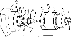
The perspective view of Fig. 2 removal that is dop shown in Figure 1 from this main shaft;
Fig. 3 is the cutaway view of cutting open along Fig. 1 center line 3-3;
Fig. 3 a is the cutaway view of cutting open along Fig. 1 center line 3A-3A;
Fig. 4 is the cutaway view that is in removable position that is similar to Fig. 3;
Fig. 4 a is the cutaway view that the line 4A-4A along Fig. 3 A cuts open;
Fig. 5 is the cutaway view of cutting open along Fig. 1 center line 5-5;
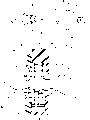
Fig. 6 is the exploded front view of locking member;
Fig. 7 is the decomposing rearview of locking member;
Fig. 8 is the perspective view that an alternative embodiment of the invention is similar to Fig. 2;
Fig. 9 is the cutaway view of cutting open at assembled state lower edge Fig. 8 center line 9-9;
Fig. 9 a is a cutaway view identical with Fig. 9 but that this support member is depressed;
Figure 10 is the decomposition diagram of locking member shown in Figure 8;
Figure 11 is the exploded view that an alternative embodiment of the invention is similar to Fig. 2;
Figure 12 is the cutaway view of cutting open at assembled state lower edge Figure 11 center line 12-12;
Figure 13 cuts open but support member is in the cutaway view of depressing position along Figure 11 center line 13-13;
Figure 14 is the diagrammatic sketch that is similar to Figure 13, but this support member is in locked position;
Figure 15 is the decomposition diagram of locking member shown in Figure 11;
Figure 16 is the exploded view that an alternative embodiment of the invention is similar to Fig. 2;
Figure 17 is the cutaway view of cutting open at assembled state lower edge Figure 16 center line 17-17;
Figure 18 is the cutaway view of cutting open along Figure 15 center line 18-18, but this support member is in depressing position;
Figure 19 is the diagrammatic sketch that is similar to Figure 18, but this support member is in locked position;
Figure 20 is the decomposition diagram of locking member shown in Figure 15.
The specific embodiment
Referring to each accompanying drawing, particularly attached Fig. 1 and 2, a kind of detachable chuck 20 is installed on the instrument 22 shown in it.In this specific embodiment, this instrument 22 is rotary drillings, yet percussion drill and powered screwdriver can be worked too well.This rotary drilling 22 comprises main shaft 24, and this main shaft comprises the hole 28 of loading this tool heads 30 again.This main shaft 24 comprises circumferential groove 26 and a plurality of projection piece 32 that is separated by axial passage 33.In addition, spacing ring 36 is placed in the lip-deep groove 40 of shoulder of main shaft, is used to limit this dop 20 backward overexercise on this main shaft 24.Magnet 38 is arranged in the main shaft 24, is used to make this tool heads 30 magnetization, and this tool heads is remained in this hole.Similarly, this projection piece 32 provides with the driving of this dop 20 with passage 33 and is connected.Other effective locking devices can be arranged in this main shaft, are used to make this tool heads to fix.
This retaining mechanism 60 comprises that one drives lining or sleeve pipe 62.This sleeve pipe 62 (preferably referring to Fig. 5-7) has first barrel portion 64, thereby this barrel portion can have and is connected screw thread or similar portions 66 that this sleeve pipe 62 and this dop body 50 is fixing with the screwed hole 68 at these dop body 50 rear portions.Second barrel portion 70 of this sleeve pipe 62 has hole 72, and corresponding projection piece 74 and axial passage 75 set within it on the surface, are used for cooperating with this main shaft 24.Each deep-slotted chip breaker 77 passes this second barrel portion and forms, and makes bias piece be used for this sleeve pipe 62 is linked to each other with main shaft 24.
The second portion 70 back connection orchids 78 of this sleeve pipe.This flange 78 comprises a pair of groove 80.Each groove 80 separates 180 ° each other.
This retaining mechanism 60 also comprises 82, the second non-rotating 84 of first revolving parts and bias piece 86.This revolving part 82 has and has the annular solid 88 that extends lining 90.This lining 90 comprises first diameter parts 92, and the size of this part is convenient to it is bearing on second barrel portion 70 of this sleeve pipe 62.Second diameter parts 94 provides thin wall section for this rotatable 82, therefore can be made by injection moulding process.The 3rd diameter parts 96 comprises eccentric cam surface 98.The 4th diameter parts 100 limits mating flanges 102.
This non-rotating 84 comprises annular solid 104.This annular solid 104 has hole 106, and first diameter parts 108 in this hole is bearing on second barrel portion 70 of this sleeve pipe, and second diameter parts 110 in this hole is used to accommodate this casing flange 78.This second diameter parts 110 comprises each lug 112.Each lug 112 is used for cooperating with each groove 80 of this flange, thereby should non-rotating 84 fixing with this sleeve pipe 62.
At least one positioning boss 114 begins to extend from this annular solid 104.These boss 114 these bias pieces 86 of location.Mating flanges 116 begins to extend from this annular solid 104.This mating flanges 116 cooperates with reception mating flanges 102, and this revolving part is connected with non-rotating maintenance.
This bias piece 86 has lateral arms 126 and each supporting leg 128,130, and it is one inverted U-shaped on the whole.This bias piece 86 is made by spring wire.This lateral arms 126 comprises extension 132.This lateral arms also can have the profile of crawling shown in Figure 4.This supporting leg 128 and 130 is the minute surface reflective graphics each other.This supporting leg 128 and 130 comprises that there are angle part 136 and crooked foot 138 in first 134, the second.This foot 138 fits in the groove of each groove 77 of this sleeve pipe and main shaft as shown in Figure 3.
In use, this foot 138 is bearing in the groove 26 of this sleeve pipe 62 and this main shaft, is used for dop 20 is connected with this main shaft 24.Therefore, this dop 20 is locked on this main shaft.When this rotatable 82 rotation, this cam face 98 is pressed against on the lateral arms 126 of this bias piece 86.When this process took place, each foot 138 of this bias piece was striden on the curved surfaces 79 that leans against this bushing slot 77, till each foot 138 moves to the outside of main shaft cavity 26, shown in the cutaway view of Fig. 3.When this process took place, this dop can disassemble from this main shaft.Make this rotatable 82 along opposite spin, remove fastening force, make this bias piece 86 be returned to initial position, each foot 138 is returned in each groove 77 of this sleeve pipe.When being in primary importance for rotatable, locking device 120 snaps in the groove 122, and this shows that it is in primary importance.For this dop and this main shaft are reconnected, this sleeve pipe 62 slides on this main shaft 24, and this moment, the chamfer surface of this main shaft contacted with the foot 138 of this bias piece, this foot 138 is separated from each other opens, and they are striden lean against on this main shaft 24.When active force continued to act on this dop 20 vertically, each foot 138 and main shaft cavity 26 contacts that are connected bias piece 86 again coupled together dop 20 and main shaft 24 then.
Forward to shown in Fig. 8-10, it shows another embodiment.Components identical will be represented with identical Reference numeral.The difference of each detachable dop is retaining mechanism.
Forward to shown in Figure 8, this detachable chuck 20 ' comprise dop body 50, each claw piece 52 and Locking bushing 54, they all be in a conventional way drill bit is fixed on this dop 20 ' in.This retaining mechanism 60 ' be arranged on the rear portion of this dop body 50, make this dop be fastened to this main shaft 24 ' on, and disassemble from this main shaft.This main shaft 24 ' with aforesaid identical; But its circumferential groove 26 is with a plurality of cavitys 26 ' replaced on projection piece 32.
Retaining mechanism 60 ' comprise drive sleeve 62, this sleeve pipe comprises first barrel portion 64, this first barrel portion has screw thread or similar portions 66, and this threaded portion 66 is connected with the screwed hole 68 at the rear portion of this dop body 50, is used to make this sleeve pipe and this dop body 50 fixing.Second barrel portion 70 of this sleeve pipe 62 has hole 72, and simultaneously corresponding projection piece 74 and axial passage 75 are arranged on the inside in this hole, with this main shaft 24 ' cooperate.Hole 77 ' pass this second barrel portion to form couples together this sleeve pipe 62 and this main shaft 24 with pin.
The a pair of housing component 150 and 152 that accommodates movable support member 154 of this retaining mechanism 60 ' comprise.The dish that this housing component 150 and 152 is normally flat and have the cup-shaped cylindrical element of the lining 158 that holds arm 154.
This support member 154 is oval-shaped on the whole, has drive part 162, and a pair of supporting leg 164 and 166 reaches the bottom transverse support arm 168 that connects each supporting leg at each supporting leg one end.Top at each supporting leg comprises otch 170 with the support member 154 that each supporting leg 164 couples together, and this otch 170 has elongated extension 172.Extend towards the top of the drive part 162 of this support member this otch extension 172.
In case assemble, this detachable chuck retaining mechanism work is as follows: as shown in Figure 9, the pin 176 pass this sleeve pipe and enter this main shaft 24 ' cavity 26 ' one of in.Shown in Fig. 9 a, the drive part 162 of this support member 154 is pushing and pressing pressing spring 174 inwardly.When this phenomenon produces, pin 176 from cavity 26 ' release.Therefore, dop can disassemble from this main shaft.When this dop turned back in this main shaft again, this pin contacted with the tapering part of this extension, stride to lean against on this extension 32, up to it and this cavity 26 ' till contacting, at this moment, this spring force this pin return this cavity 26 ' in.
Therefore, support member 154 produces motion, compresses this spring, and this spring makes the cavity 26 ' middle release of this pin from this main shaft again, thereby removes this dop.
Forward Figure 11-15 to, wherein show another embodiment.Components identical is represented with identical Reference numeral.Difference between this detachable chuck is the retaining mechanism difference.
Referring to Figure 11, detachable chuck 120 comprises dop body 50, each claw piece 52 and Locking bushing 54, and they all are in the usual way this drill bit to be fixed in this dop 120.This retaining mechanism 160 is arranged on the rear portion of this dop body 50, is used to make this dop to be fixedly attached to this main shaft 24, and disassembles from this main shaft.
This retaining mechanism 160 comprises drive sleeve 62, this sleeve pipe 62 comprises first barrel portion 64, this first barrel portion can have screw thread or similar portions 66, and this part 66 is connected with the screwed hole 68 at these dop body 50 rear portions, thereby this sleeve pipe is fixedlyed connected with dop body 50.Second barrel portion 70 of this sleeve pipe 62 has hole 72, and simultaneously corresponding projection piece 74 and axial passage 75 are arranged on the inside in this hole, cooperate with this main shaft 24.Groove 177 passes this second barrel portion 70 and forms, and with a stay this sleeve pipe 62 is coupled together with this main shaft 24.
This retaining mechanism 160 comprises a pair of housing component 150 and 152 that accommodates movable support member 154.Normally flat dish of this housing component 150 and 152 and cup-shaped cylindrical part, cup-shaped cylindrical part comprises the lining 158 that holds support member 154.This housing 152 comprises the lug that each cooperates with otch 80 in this sleeve pipe 62.
This support member 154 has drive part 162, and a pair of supporting leg 164 and 166 reaches the bottom horizontal support arm 168 that connects each supporting leg at this supporting leg one end, and it is oval-shaped on the whole.This support member 154 connects supporting leg 164 and 166 at its top, and comprises the otch 170 with elongated extension 172.Extend towards the top of the drive part 162 of this support member this otch extension 172.
In case after assembling, this detachable chuck retaining mechanism work is as follows: as Figure 12 and 14 can find out, stay 176 ' pass this sleeve pipe also entered in the cavity 26 of this main shaft 24.The drive part 162 of this support member 154 is pushed away inwardly, and the effect of spring 174 is lived in opposing, as shown in figure 13.When this process takes place, this stay 176 ' from cavity 26, withdraw from.Therefore, this dop 120 can disassemble from this main shaft.When this dop turned back in this main shaft again, this stay contacted with the tapering part of this extension, strode to lean against on this extension 32, contacted with each cavity 26 up to it, and at this moment, this spring forces this stay 176 ' get back in this cavity 26.
Therefore, support member 154 moves, so that compress this spring, this spring makes again in the cavity 26 of this stay from this main shaft and withdraws from, thereby removes this dop.
Forward Figure 16-20 to, wherein show another embodiment.Components identical is represented with identical Reference numeral.Difference between each detachable chuck is its retaining mechanism difference.
Referring to Figure 16, detachable chuck 220 comprises a dop body 50, each claw piece 52 and Locking bushing 54, and they all are in the usual way this drill bit to be fixed in this dop 220.This retaining mechanism 260 is arranged on the rear portion of this dop body 50, is used to make this dop to be fixedly attached to this main shaft 24, and disassembles from this main shaft.
This retaining mechanism 260 comprises drive sleeve 62, this sleeve pipe 62 comprises first barrel portion 64, this first barrel portion can have a screw thread or similar portions 66, and this part 66 is connected with the screwed hole 68 at these dop body 50 rear portions, thereby this sleeve pipe is fixedlyed connected with dop body 50.Second barrel portion 70 of this sleeve pipe 62 has hole 72, and simultaneously corresponding projection piece 74 and axial passage 75 are arranged on the inside in this hole, cooperate with this main shaft 24.A pair of groove 277 passes this second barrel portion 70 and forms, and with stay this sleeve pipe 62 is coupled together with this main shaft 24.
This retaining mechanism 260 comprises a pair of housing component 262 and 264 that accommodates a pair of stay carrier 266,268 and a pair of actuator 270,272.This housing component 262 and 264 boths are the cup-shaped cylindrical parts that have lining 274 and 276, and this lining accommodates this stay carrier and actuator.This housing component 264 can comprise an annular cavity 278 that accommodates the lining 54 of this dop body 50.Housing component 262 comprises spring base 282.Housing component 262 also comprises the lug that engages with otch 80 on the sleeve pipe 62.
Each stay carrier 266,268 is C shape on the whole.Each end 284,286 comprises cam face 288,290.In addition, end 284,186 also comprises spring housing 292,294.Spring 296 is arranged in this spring housing 292,294, and applies bias voltage between housing substrate 298 and spring base 282.This stay carrier 266,268 comprises the groove 300 that accommodates stay 302.Each stay 302 comprises the otch 304 that accommodates pin 306, and this pin extends through the hole 308 in this stay carrier 266,268, and each stay 302 is locked in the stay carrier 266,268.Each stay 302 comprises a curved surface that combines with groove 26 in this main shaft 24.
Actuator 270,272 comprises first 310 and second portion 312.This first 310 extends to the outside of this housing component 262,264, and is controlled by the user.This second portion 312 is a V-arrangement, has cam face 314,316.Each cam face 314,316 contacts with the cam face 288,290 of this stay carrier 266,268.
In case after having assembled, this detachable chuck retaining mechanism work is as follows: shown in Figure 17-19, stay 302 passes this sleeve pipe and enters in one of the cavity 26 of this main shaft 24.The first 310 of this actuator 270,272 pushes away inwardly.Cam face 314,316 pushings are against the cam face 288,290 of living this stay carrier 266,268.Then, this stay carrier 266,268 is compressed in the spring 296 between spring base 282 and 298, as shown in figure 19.When this phenomenon produced, this stay 302 withdrawed from from cavity 26.Therefore, dop can disassemble from this main shaft.When this dop turned back in this main shaft again, this stay 302 contacted with the tapering part of this extension, strode to lean against on this extension 32, and with till this cavity 26 contacts, at this moment, this spring forces this stay 302 to return in this cavity 26 up to it.
Therefore, each stay carrier 266,268 moves, so that compress this spring, this spring makes in each stay each cavity 26 from this main shaft and withdraws from then, thereby removes this dop.
Although the above-mentioned the preferred embodiments of the present invention that describe in detail, under the situation of scope that does not break away from follow-up each claim and equivalent meanings, be easy to the present invention make improvements, modification and replacement.
Claims (36)
1. detachable chuck, it comprises:
Be used for the lining that is connected with rotary main shaft;
The dop that is connected with described lining;
Be used for described lining is clamped on retaining mechanism on this rotary main shaft; Described retaining mechanism comprises that at least one is bearing in the stay in the cavity in this main shaft, and described at least one stay can move to the second place of the cavity disengagement of described at least one stay and this main shaft from the primary importance that this lining and this main shaft cavity are coupled together; And
Described at least one stay applies bias voltage between the described primary importance and the described second place, be in non-bias state at described at least one stay of described primary importance, at this moment, described lining and described principal shaft locking, in the described second place, described at least one stay is in bias state, and described lining is disassembled from described main shaft.
2. detachable chuck as claimed in claim 1 is characterized in that described retaining mechanism comprises a pair of stay.
3. detachable chuck as claimed in claim 2, it is characterized in that, described retaining mechanism comprises housing, the first and second stay carriers in described housing, the described first and second stay carriers each all with described stay in one be connected, the actuator that a pair of and described first and second stay carriers are connected, with the bias piece that is used for the described first and second stay carriers of bias voltage, described a pair of actuator is stated between the described primary importance of being biased in of bias piece and the second place described first and second stay carriers opposing residence and is moved, so that lock and unload described lining from main shaft.
4. detachable chuck as claimed in claim 3, it is characterized in that, each all comprises cam face described a pair of actuator and the described first and second stay carriers, described cam face acts on the relative cam face, so as to make described stay between described first and second positions towards perpendicular to the axial-movement of described main shaft.
5. detachable chuck as claimed in claim 4 is characterized in that, the described first and second stay carriers are C shape on the whole.
6. detachable chuck as claimed in claim 4 is characterized in that each actuator has the pair of cams surface.
7. detachable chuck as claimed in claim 1 is characterized in that, described retaining mechanism comprise with described at least one be used for the support member that is connected with the stay of the cavity combination of described main shaft.
8. detachable chuck as claimed in claim 7 is characterized in that, described retaining mechanism comprises be used to spring that described support member is moved between described first and second positions.
9. detachable chuck as claimed in claim 8 is characterized in that described spring is a helical spring, and the described spring that is in non-biased position makes the part of described support member keep approaching the user.
10. hand-held tool, it comprises:
The hand-held tool that has rotatable shaft, described main shaft comprises cavity; With
Detachable chuck, described detachable chuck comprises: the lining that is connected with this rotatable main shaft; The dop that is connected with described lining;
Be used for described lining is locked at retaining mechanism on this rotary main shaft, described retaining mechanism comprises the stay at least one cavity that is bearing in this main shaft, and the primary importance that described at least one stay can couple together from the cavity with this lining and this main shaft moves to the second place of described at least one stay and the disengagement of this main shaft cavity; And
Described at least one stay applies bias voltage between the described primary importance and the described second place, be in non-bias state at described at least one stay of described primary importance, at this moment, described lining and described principal shaft locking, in the described second place, described at least one stay is in bias state, and described lining is disassembled from described main shaft.
11. hand-held tool as claimed in claim 10 is characterized in that, described retaining mechanism comprises a pair of stay.
12. hand-held tool as claimed in claim 11, it is characterized in that, described retaining mechanism comprises housing, the first and second stay carriers in described housing, the described first and second stay carriers each all with described stay in one be connected, the actuator that a pair of and described first and second stay carriers are connected, with the bias piece that is used for the described first and second stay carriers of bias voltage, described a pair of actuator makes described first and second stay carriers opposing residence state being biased between the primary importance and the second place of bias piece and moves, so that lock and unload described lining from described main shaft.
13. hand-held tool as claimed in claim 12, it is characterized in that, each all comprises cam face described a pair of actuator and the described first and second stay carriers, described cam face acts on the relative cam face, so as to make described stay between described first and second positions towards perpendicular to the axial-movement of described main shaft.
14. hand-held tool as claimed in claim 13 is characterized in that, the described first and second stay carriers are C shape on the whole.
15. hand-held tool as claimed in claim 13 is characterized in that, each actuator has the pair of cams surface.
16. hand-held tool as claimed in claim 10 is characterized in that, described retaining mechanism comprise with described at least one be used for the support member that is connected with the stay of the cavity combination of described main shaft.
17. hand-held tool as claimed in claim 16 is characterized in that, described retaining mechanism comprises be used to spring that described support member is moved between described first and second position.
18. hand-held tool as claimed in claim 17 is characterized in that, described spring is a helical spring, and the described spring that is in non-biased position makes the part of described support member keep approaching the user.
19. a detachable chuck, it comprises:
Be used for the lining that is connected with rotary main shaft;
The dop that is connected with described lining;
Be used for described lining is clamped on retaining mechanism on this rotary main shaft; Described retaining mechanism comprises the locking member in the cavity that is bearing in this main shaft, and described locking member can move to the second place of the cavity disengagement of described locking member and this main shaft from the primary importance that this lining and this main shaft cavity are coupled together; And
Described locking member applies bias voltage between the described primary importance and the described second place, be in non-bias state at the described locking member of described primary importance, at this moment, described lining and described principal shaft locking, in the described second place, described locking member is in bias state, and described lining is disassembled from described main shaft, and wherein said locking member is in non-bias state.
20. detachable chuck as claimed in claim 19 is characterized in that, described locking member comprises on the whole for U-shaped so that with the spring of described lining and described principal shaft locking.
21. detachable chuck as claimed in claim 19, it is characterized in that, described locking member comprises first revolving part and second non-rotating, and bias piece, described rotatable moves described bias piece between described first and second positions, so that lock and dismantle described lining from described main shaft.
22. detachable chuck as claimed in claim 21, it is characterized in that, described rotatable comprises the cam face that acts on the described bias piece, and described bias piece court between the described primary importance and the second place is moved perpendicular to the direction of the axis of described main shaft.
23. detachable chuck as claimed in claim 22 is characterized in that, described bias piece is one and is the spring of U-shaped on the whole.
24. detachable chuck as claimed in claim 21 is characterized in that, described non-rotating and revolving part comprise makes their interconnective flanges.
25. detachable chuck as claimed in claim 24, it is characterized in that, locking device is connected with described non-rotating, and described rotatable comprise the groove that is used to accommodate described locking device, is in described primary importance so that demonstrate described revolving part effectively.
26. a hand-held tool, it comprises:
Hand-held tool with a rotary main shaft, described main shaft comprises cavity; With
Detachable chuck, described detachable chuck comprises: be used for the lining that is connected with rotary main shaft; The dop that is connected with described lining;
Be used for described lining is clamped on retaining mechanism on this rotary main shaft; Described retaining mechanism comprises the locking member in the cavity that is bearing in this main shaft, and described locking member can move to the second place of the cavity disengagement of described locking member and this main shaft from the primary importance that this lining and this main shaft cavity are coupled together; And
Described locking member applies bias voltage between the described primary importance and the described second place, be in non-bias state at the described locking member of described primary importance, at this moment, described lining and described principal shaft locking, in the described second place, described locking member is in bias state, and described lining is disassembled from described main shaft, and wherein said locking member is in non-bias state.
27. hand-held tool as claimed in claim 26 is characterized in that, described locking member comprises on the whole for U-shaped so that with the spring of described lining and described principal shaft locking.
28. hand-held tool as claimed in claim 26, it is characterized in that, described locking member comprises first revolving part and second non-rotating, and bias piece, described rotatable moves described bias piece between described first and second positions, so that lock and dismantle described lining from described main shaft.
29. hand-held tool as claimed in claim 28, it is characterized in that, described rotatable comprises the cam face that acts on the described bias piece, and described bias piece court between the described primary importance and the second place is moved perpendicular to the direction of the axis of described main shaft.
30. hand-held tool as claimed in claim 28 is characterized in that, described bias piece is to be the spring of U-shaped on the whole.
31. detachable dop as claimed in claim 19 is characterized in that described locking member comprises support member, has pin, so that combine with cavity in the described main shaft.
32. detachable dop as claimed in claim 31 is characterized in that described locking member comprises spring, so that described support member is moved between described first and second positions.
33. detachable chuck as claimed in claim 32 is characterized in that, described spring is a helical spring, and the described spring that is in non-biased position makes the part of described support member keep approaching the user.
34. hand-held tool as claimed in claim 26 is characterized in that, described locking member comprises support member, has pin, so that combine with cavity in the described main shaft.
35. hand-held tool as claimed in claim 34 is characterized in that, described locking member comprises spring, so that described support member is moved between described first and second positions.
36. hand-held tool as claimed in claim 35 is characterized in that, described spring is a helical spring, and the described spring that is in non-biased position makes the part of described support member keep approaching the user.
Applications Claiming Priority (4)
| Application Number | Priority Date | Filing Date | Title |
|---|---|---|---|
| US09/782,812 | 2001-02-14 | ||
| US09/782,812 US6550786B2 (en) | 1997-12-12 | 2001-02-14 | Removable chuck |
| US09/812,745 US6688611B2 (en) | 1997-12-12 | 2001-03-20 | Removable chuck |
| US09/812,745 | 2001-03-20 |
Publications (1)
| Publication Number | Publication Date |
|---|---|
| CN1370657A true CN1370657A (en) | 2002-09-25 |
Family
ID=27120050
Family Applications (1)
| Application Number | Title | Priority Date | Filing Date |
|---|---|---|---|
| CN02103287.4A Pending CN1370657A (en) | 2001-02-14 | 2002-02-14 | Detachable chuck |
Country Status (7)
| Country | Link |
|---|---|
| EP (1) | EP1236538B1 (en) |
| CN (1) | CN1370657A (en) |
| AT (1) | ATE329724T1 (en) |
| AU (1) | AU782429B2 (en) |
| CA (1) | CA2370981C (en) |
| DE (1) | DE60212223T2 (en) |
| NZ (1) | NZ517133A (en) |
Cited By (10)
| Publication number | Priority date | Publication date | Assignee | Title |
|---|---|---|---|---|
| CN101553344B (en) * | 2006-12-08 | 2012-07-04 | 罗伯特·博世有限公司 | Tip attachments for hand tools |
| CN102958633A (en) * | 2010-06-23 | 2013-03-06 | 罗伯特·博世有限公司 | Hand-held machine tools with impact mechanism |
| CN103042507A (en) * | 2011-10-14 | 2013-04-17 | 罗伯特·博世有限公司 | Tool attachment |
| CN103831799A (en) * | 2012-11-22 | 2014-06-04 | 罗伯特·博世有限公司 | Tool attachment for a handheld tool machine |
| CN105033957A (en) * | 2015-08-18 | 2015-11-11 | 宁波市海联电器有限公司 | Fast disassembling and assembling structure and electric tool |
| CN108430707A (en) * | 2015-12-16 | 2018-08-21 | 罗伯特·博世有限公司 | Tool basic module |
| CN109290993A (en) * | 2018-11-12 | 2019-02-01 | 广东奥能五金工具有限公司 | Integral electric screwdriver |
| CN110065036A (en) * | 2018-01-24 | 2019-07-30 | 罗伯特·博世有限公司 | Holding meanss for hand held power machine |
| CN110300641A (en) * | 2016-12-23 | 2019-10-01 | 喜利得股份公司 | Tool device |
| CN112496881A (en) * | 2020-11-24 | 2021-03-16 | 杭州电子科技大学 | Detachable circular knife grinding power assembly |
Families Citing this family (8)
| Publication number | Priority date | Publication date | Assignee | Title |
|---|---|---|---|---|
| DE102004006205B3 (en) * | 2004-02-09 | 2005-05-19 | Hilti Ag | Drill adapter for screwdriver tool has clamping device fitted to tool end of screwdriver tool, drill chuck for drill bit and axial stop acting against tool spindle of screwdriver tool for operation of its drive coupling |
| ATE391585T1 (en) * | 2005-05-19 | 2008-04-15 | Metabowerke Gmbh | DRILLING TOOL EQUIPMENT |
| CN100398263C (en) * | 2006-08-23 | 2008-07-02 | 宁波长城精工实业有限公司 | Clamping apparatus for workpiece |
| DE102006057928A1 (en) * | 2006-12-08 | 2008-06-12 | Robert Bosch Gmbh | Attachment for a hand tool |
| CN104416543B (en) * | 2013-08-23 | 2016-08-10 | 苏州宝时得电动工具有限公司 | Electric tool termination connects adnexa and electric tool |
| CN111590524B (en) * | 2020-06-11 | 2024-11-05 | 浙江德硕科技股份有限公司 | Head and body quick-change structure of multifunctional power tool and multifunctional power tool |
| US12594657B2 (en) | 2023-11-30 | 2026-04-07 | Stanley Black & Decker, Inc. | Multi-headed power tool and systems for fastening heads thereon |
| WO2025117585A1 (en) * | 2023-11-30 | 2025-06-05 | Stanley Black & Decker, Inc. | Multi-headed power tool and fastening system for same and systems for fastening heads thereon |
Family Cites Families (5)
| Publication number | Priority date | Publication date | Assignee | Title |
|---|---|---|---|---|
| US4514117A (en) * | 1981-06-08 | 1985-04-30 | Larry Scott | Quick-change tool holder and tool |
| DE3636027A1 (en) * | 1986-10-23 | 1988-04-28 | Hilti Ag | HAND DEVICE WITH DETACHABLE TOOL HOLDER |
| DE9203627U1 (en) * | 1992-03-18 | 1993-07-22 | Robert Bosch Gmbh, 70469 Stuttgart | Hand tool with tool holder |
| US5951026A (en) * | 1997-12-12 | 1999-09-14 | Black & Decker Inc. | Removable chuck |
| US6079716A (en) * | 1997-12-12 | 2000-06-27 | Black & Decker Inc. | Removable chuck |
-
2002
- 2002-02-06 CA CA002370981A patent/CA2370981C/en not_active Expired - Fee Related
- 2002-02-11 AT AT02250917T patent/ATE329724T1/en not_active IP Right Cessation
- 2002-02-11 EP EP02250917A patent/EP1236538B1/en not_active Expired - Lifetime
- 2002-02-11 NZ NZ517133A patent/NZ517133A/en active Application Revival
- 2002-02-11 DE DE60212223T patent/DE60212223T2/en not_active Expired - Lifetime
- 2002-02-13 AU AU15597/02A patent/AU782429B2/en not_active Ceased
- 2002-02-14 CN CN02103287.4A patent/CN1370657A/en active Pending
Cited By (21)
| Publication number | Priority date | Publication date | Assignee | Title |
|---|---|---|---|---|
| US8360439B2 (en) | 2006-12-08 | 2013-01-29 | Robert Bosch Gmbh | Adapter for a hand-held power tool |
| CN102632487B (en) * | 2006-12-08 | 2014-09-24 | 罗伯特·博世有限公司 | Adapter for a handheld machine tool |
| CN101553344B (en) * | 2006-12-08 | 2012-07-04 | 罗伯特·博世有限公司 | Tip attachments for hand tools |
| CN102958633A (en) * | 2010-06-23 | 2013-03-06 | 罗伯特·博世有限公司 | Hand-held machine tools with impact mechanism |
| US9999930B2 (en) | 2010-06-23 | 2018-06-19 | Robert Bosch Gmbh | Hand-held machine tool having a striking mechanism |
| CN102958633B (en) * | 2010-06-23 | 2015-07-08 | 罗伯特·博世有限公司 | Hand-held machine tools with impact mechanism |
| CN103042507B (en) * | 2011-10-14 | 2017-03-01 | 罗伯特·博世有限公司 | Attachment |
| CN103042507A (en) * | 2011-10-14 | 2013-04-17 | 罗伯特·博世有限公司 | Tool attachment |
| CN103831799B (en) * | 2012-11-22 | 2017-10-03 | 罗伯特·博世有限公司 | The attachment of hand held power machine |
| US9694428B2 (en) | 2012-11-22 | 2017-07-04 | Robert Bosch Gmbh | Tool attachment for a hand-held machine tool |
| CN103831799A (en) * | 2012-11-22 | 2014-06-04 | 罗伯特·博世有限公司 | Tool attachment for a handheld tool machine |
| CN105033957A (en) * | 2015-08-18 | 2015-11-11 | 宁波市海联电器有限公司 | Fast disassembling and assembling structure and electric tool |
| CN108430707A (en) * | 2015-12-16 | 2018-08-21 | 罗伯特·博世有限公司 | Tool basic module |
| CN108430707B (en) * | 2015-12-16 | 2022-07-19 | 罗伯特·博世有限公司 | Tool basic module |
| CN110300641A (en) * | 2016-12-23 | 2019-10-01 | 喜利得股份公司 | Tool device |
| US11370101B2 (en) | 2016-12-23 | 2022-06-28 | Hilti Aktiengesellschaft | Tool device |
| CN110300641B (en) * | 2016-12-23 | 2023-01-13 | 喜利得股份公司 | Tool device |
| CN110065036A (en) * | 2018-01-24 | 2019-07-30 | 罗伯特·博世有限公司 | Holding meanss for hand held power machine |
| CN109290993A (en) * | 2018-11-12 | 2019-02-01 | 广东奥能五金工具有限公司 | Integral electric screwdriver |
| CN112496881A (en) * | 2020-11-24 | 2021-03-16 | 杭州电子科技大学 | Detachable circular knife grinding power assembly |
| CN112496881B (en) * | 2020-11-24 | 2022-03-11 | 杭州电子科技大学 | Detachable circular knife grinding power assembly |
Also Published As
| Publication number | Publication date |
|---|---|
| NZ517133A (en) | 2004-05-28 |
| ATE329724T1 (en) | 2006-07-15 |
| EP1236538B1 (en) | 2006-06-14 |
| EP1236538A3 (en) | 2002-09-18 |
| AU782429B2 (en) | 2005-07-28 |
| EP1236538A2 (en) | 2002-09-04 |
| DE60212223D1 (en) | 2006-07-27 |
| CA2370981A1 (en) | 2002-08-14 |
| DE60212223T2 (en) | 2007-05-16 |
| CA2370981C (en) | 2009-12-29 |
| AU1559702A (en) | 2002-08-15 |
Similar Documents
| Publication | Publication Date | Title |
|---|---|---|
| CN1370657A (en) | Detachable chuck | |
| CN1506185A (en) | Tool-less blade holder for changing the saw blade of a reciprocating tool | |
| US6820339B2 (en) | Right-angle accessory saw for use with electric drill | |
| CN1047744C (en) | Device for clamping the shank of the tool holder | |
| US6178646B1 (en) | Blade clamping system for a jigsaw | |
| CN1221217C (en) | Rotary button fixator for vertebration fixing | |
| CN1097496C (en) | Molded chuck | |
| CN1572403A (en) | Handle arrangement for a power tool | |
| CN1047743C (en) | Apparatus for holding toolholder shank utilizing rotatable cam to minimize kickback | |
| CN101032771A (en) | Clutch mechanism | |
| CN1942276A (en) | Automated chuck exchange using rotating turret | |
| CN1454756A (en) | Electric cutter | |
| CN1853863A (en) | Screwdriver | |
| CN1798632A (en) | hand tool machine | |
| CN1541148A (en) | cutting tool | |
| CN2623404Y (en) | Reciprocating electric grinder | |
| CN1210053A (en) | Chuck device for quick tool changeover | |
| EP2987590A1 (en) | Screw clamping device and screw tool | |
| CN1596169A (en) | Tool for chip removing machining having a wedge-actuated insert adjustment mechanism | |
| CN1852789A (en) | electric screw driver | |
| CN1527756A (en) | Clamp forceps | |
| US20020131818A1 (en) | Fastening means | |
| US6193241B1 (en) | Tool drive system | |
| US4934034A (en) | Tool holder assembly for a portable machining device | |
| CN1903488A (en) | Knives rack clamping unit for main shaft device |
Legal Events
| Date | Code | Title | Description |
|---|---|---|---|
| C06 | Publication | ||
| PB01 | Publication | ||
| C10 | Entry into substantive examination | ||
| SE01 | Entry into force of request for substantive examination | ||
| C12 | Rejection of a patent application after its publication | ||
| RJ01 | Rejection of invention patent application after publication |