CN1375845A - Lighting parts and lighting apparatus using said lighting parts - Google Patents
Lighting parts and lighting apparatus using said lighting parts Download PDFInfo
- Publication number
- CN1375845A CN1375845A CN02107791.6A CN02107791A CN1375845A CN 1375845 A CN1375845 A CN 1375845A CN 02107791 A CN02107791 A CN 02107791A CN 1375845 A CN1375845 A CN 1375845A
- Authority
- CN
- China
- Prior art keywords
- light
- button
- electrode layer
- lighting
- layer
- Prior art date
- Legal status (The legal status is an assumption and is not a legal conclusion. Google has not performed a legal analysis and makes no representation as to the accuracy of the status listed.)
- Granted
Links
Images




Classifications
-
- H—ELECTRICITY
- H01—ELECTRIC ELEMENTS
- H01H—ELECTRIC SWITCHES; RELAYS; SELECTORS; EMERGENCY PROTECTIVE DEVICES
- H01H13/00—Switches having rectilinearly-movable operating part or parts adapted for pushing or pulling in one direction only, e.g. push-button switch
- H01H13/70—Switches having rectilinearly-movable operating part or parts adapted for pushing or pulling in one direction only, e.g. push-button switch having a plurality of operating members associated with different sets of contacts, e.g. keyboard
- H01H13/702—Switches having rectilinearly-movable operating part or parts adapted for pushing or pulling in one direction only, e.g. push-button switch having a plurality of operating members associated with different sets of contacts, e.g. keyboard with contacts carried by or formed from layers in a multilayer structure, e.g. membrane switches
-
- H—ELECTRICITY
- H01—ELECTRIC ELEMENTS
- H01H—ELECTRIC SWITCHES; RELAYS; SELECTORS; EMERGENCY PROTECTIVE DEVICES
- H01H2219/00—Legends
- H01H2219/002—Legends replaceable; adaptable
- H01H2219/018—Electroluminescent panel
- H01H2219/02—Electroluminescent panel programmable
Landscapes
- Push-Button Switches (AREA)
- Switch Cases, Indication, And Locking (AREA)
Abstract
一种照明部件,包括:多个按钮;通过按压按钮的操作来进行通电、断电的开关元件;具有与在开关元件的上方和下方的至少一方上配置的多个按钮对应的发光部的EL元件;并且,EL元件在光透过性的绝缘基体材料上,具有与发光部对应并选择性地层叠的光透过性电极、发光体层和背面电极层。通过构成具有以上所述结构的照明部件,就能得到清晰的照明,并能实现使用零件数和安装工时都比较少的照明部件。
A lighting component comprising: a plurality of buttons; a switch element for turning on and off power by pressing the button; element; and, the EL element has a light-transmitting electrode, a light-emitting body layer, and a back electrode layer that are selectively laminated corresponding to the light-emitting part on the light-transmitting insulating base material. By constituting the lighting unit having the above-mentioned structure, clear lighting can be obtained, and a lighting unit with a relatively small number of parts and few installation man-hours can be realized.
Description
技术领域technical field
本发明涉及一种用于移动电话和个人计算机等各种电子仪器中的照明部件和使用该照明部件的照明装置。The present invention relates to a lighting component used in various electronic devices such as mobile phones and personal computers, and a lighting device using the lighting component.
背景技术Background technique
近年来,随着移动电话和个人计算机等各种电子仪器的高功能化和多样化的发展,对这些仪器中使用的照明部件也提出了各种各样的照明以及操作功能方面的要求。In recent years, as various electronic devices such as mobile phones and personal computers have become more sophisticated and diversified, various lighting and operational functions have been demanded for lighting components used in these devices.
下面,参照图7就以往的此类照明部件加以说明。Hereinafter, a conventional lighting unit of this type will be described with reference to FIG. 7 .
图7是以往的照明部件的剖视图。在图7中,绝缘树脂制的多个按钮1具有半透明或乳白色等的导光部1A和覆盖了导光部1A的暗色的遮光部1B,在按钮1的上面设置有显示部1C即导光部1A露出了文字、符号以及图案等的形状的状态。Fig. 7 is a cross-sectional view of a conventional lighting component. In FIG. 7, a plurality of buttons 1 made of insulating resin have a translucent or milky white
而且,在按钮1的下面配置的开关元件2是膜片开关,其结构如下:在上下面形成有多个布线图案(无图示)的布线衬底3和具有可挠性的绝缘薄膜4通过在两面上涂抹了粘合剂的绝缘垫片5贴在一起,在布线衬底3的上面上形成的固定接点3A和在绝缘薄膜4的下面上形成的可动接点4A以给定的间隔对置。Furthermore, the
另外,把发光二极管(以下称作LED)6安装在固定接点3A附近的布线衬底3的上面上,把LED7安装在液晶显示装置(以下称作LCD)8的下方,并在LED7和LCD8之间配置有光扩散板9。In addition, a light emitting diode (hereinafter referred to as LED) 6 is installed on the
而且,使按钮1能从覆盖这些部分的绝缘树脂制的箱体10上面的开口孔上下移动,据此构成了照明部件。Furthermore, the button 1 is made to be able to move up and down from the opening hole on the upper surface of the insulating
在以上所述的结构中,如果对按钮1的上面进行按压操作,则上面被按压的绝缘薄膜4向按钮1的下面的按压部1D弯曲,并且,其下面上的可动接点4A与布线衬底3上面的固定接点3A接触,使开关元件2通电。接着,如果解除按压力,则通过绝缘薄膜4的弹性恢复力,按钮1向上方移动,并且可动接点4A从固定接点3A上离开,恢复到原来的状态。In the structure described above, if the upper surface of the button 1 is pressed, the
而且,如果LED6发光,则此光通过导光部1A从下面照射按钮1的显示部1C,因此即使在周围较暗的情况下,也能确认显示部1C上的文字、记号和图案等,从而对按钮1进行识别。Moreover, if the
而且,如果LED7发光,则因为此光被光扩散板9扩散,从下面照射LCD8,所以能比较容易地对LCD8上表示的文字等进行视觉识别。And when LED7 emits light, since this light is diffused by the light-diffusion plate 9, and irradiates LCD8 from below, the character etc. which are displayed on LCD8 can be visually recognized comparatively easily.
可是,在所述以往的照明部件中,因为通过LED6和LED7进行按钮1和LCD8的照明,所以在排列有多个按钮1的情况下,就需要与按钮1数量对应的LED数量,并且一旦LCD8达到某种程度的大小,就需要用多个LED来均匀地对其显示画面进行照明,所以产生了使用零部件数量增加,并且向布线衬底3上的安装也比较耗费时间这一问题。However, in the above-mentioned conventional lighting components, since the buttons 1 and the
发明内容Contents of the invention
为解决以上所述问题,本发明提供的照明部件具有:In order to solve the above-mentioned problems, the lighting component provided by the present invention has:
多个按钮;通过对按钮进行按压操作来进行通电、断电的开关元件;具有与在开关元件的上方和下方的至少一方上配置的各个按钮对应的发光部的EL元件;并且,EL元件的发光部在光透过性的绝缘基体材料上,部分地形成光透过性电极层或背面电极层的至少一方,有选择地层叠了所述光透过性电极层、发光体层和所述背面电极层。A plurality of buttons; a switch element that performs power-on and power-off by pressing the button; an EL element having a light-emitting portion corresponding to each button arranged on at least one of the upper and lower sides of the switch element; and the EL element At least one of a light-transmitting electrode layer or a back electrode layer is partially formed on a light-transmitting insulating base material in the light-emitting part, and the light-transmitting electrode layer, the luminous body layer, and the light-emitting layer are selectively laminated. backside electrode layer.
附图说明Description of drawings
下面简要说明附图。The accompanying drawings are briefly described below.
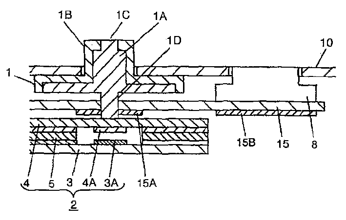
图1是本发明的实施例1的照明部件的剖视图。Fig. 1 is a cross-sectional view of a lighting unit according to Embodiment 1 of the present invention.
图2是本发明的实施例1的EL元件的部分剖视图。Fig. 2 is a partial cross-sectional view of the EL element of Example 1 of the present invention.
图3是本发明实施例1的分解立体图。Fig. 3 is an exploded perspective view of Embodiment 1 of the present invention.
图4是本发明的实施例2的EL元件的部分剖视图。Fig. 4 is a partial sectional view of an EL element according to Example 2 of the present invention.
图5是本发明的实施例3的照明装置的框图。Fig. 5 is a block diagram of a lighting device according to
图6是本发明的实施例3的键盘装置的外观图。Fig. 6 is an external view of a keyboard device according to
图7是以往例的照明部件的剖视图。Fig. 7 is a cross-sectional view of a lighting component of a conventional example.
具体实施方式Detailed ways
下面,参照图1~图6,就本发明的实施例加以说明。Next, an embodiment of the present invention will be described with reference to FIGS. 1 to 6 .
实施例1Example 1
下面参照附图,就本发明的实施例1加以说明。Embodiment 1 of the present invention will be described below with reference to the accompanying drawings.
图1是本发明的实施例1的照明部件的剖视图。在图1中,ABS或聚碳酸酯、丙烯酸等绝缘树脂制的多个按钮1具有半透明或乳白色的导光部1A和覆盖导光部1A的遮光部1B,在按钮1的上面设置有显示部1C,该显示部1C即导光部1A露出的文字、符号和图案等的形状的状态。Fig. 1 is a cross-sectional view of a lighting unit according to Embodiment 1 of the present invention. In FIG. 1 , a plurality of buttons 1 made of insulating resin such as ABS, polycarbonate, or acrylic have a translucent or milky white
而且,在按钮1的下面配置的开关元件2是作为膜片开关构成的,其结构如下:将在上下面形成有多个布线图案(无图示)的纸苯酚或加入玻璃的环氧等的布线衬底3和聚对苯二甲酸乙二酯或聚酰亚胺等具有可挠性的绝缘薄膜4,粘合在两面涂有粘合剂的绝缘垫片5上,并使在布线衬底3的上面形成的固定接点3A和在绝缘薄膜4的下面上形成的可动接点4A以给定的间隔对置。Furthermore, the
另外,EL元件15配置在开关元件2的上方,在位于按钮1和配置在其侧面的LCD8等显示元件下方的下面上,设置有多个发光部15A和15B,并在按钮1下方的发光部15A上设置有用于使从按钮1的下面伸出的按压部1D贯通的通孔。In addition, the
而且,按钮1能从覆盖了这些部分的绝缘树脂制的箱体10的上面的开口孔上下移动,构成了照明部件。Furthermore, the button 1 can move up and down through the opening hole on the upper surface of the
另外,图2是以上所述那样的EL元件的部分剖视图,图3是同一部分的分解立体图。In addition, FIG. 2 is a partial sectional view of the EL element as described above, and FIG. 3 is an exploded perspective view of the same part.
在图2和图3中,聚对苯二甲酸乙二酯或聚酰亚胺等薄膜状的光透过性绝缘基体材料16的整个下面上,通过溅射法或电子束法,形成印刷有分散了氧化铟锡等的光透过性合成树脂的光透过性电极层17。In Fig. 2 and Fig. 3, on the whole underside of film-like light-transmitting
而且,在其上还印刷有在氟化橡胶或氰基树脂等中分散了作为发光母材的硫化锌等的发光体层18,并在发光体层18上印刷有在高感应性的树脂上分散了钛酸钡等的介质层19。Moreover, a
而且,在介质层19上,选择性地印刷与按钮1分别对应的银或碳树脂类的多个背面电极层20A和分别对应于显示元件LCD8的背面电极层20B,形成多个发光层15A和15B,在这些部分上覆盖环氧树脂或聚酯树脂等的绝缘层21,据此来构成EL元件15。Moreover, on the
在以上所述的结构中,如果按压按钮1的上面,则上面被按压的绝缘薄膜4向按钮1的下面的按压部1D弯曲,其下面上的可动接点4A与布线衬底3上面的固定接点3A接触,开关元件2被通电。接着,如果解除按压力,则通过绝缘薄膜4的弹性恢复力,按钮1向上方移动,可动接点4A与固定接点3A分开,恢复到原来的状态。In the structure described above, if the upper surface of the button 1 is pressed, the
另外,如果在EL元件15的光透过性电极层17和多个背面电极层20A和20B上外加电压,具有被这些电极层夹着的发光体层18的发光部15A和15B发光,在图1中,此光从下面照亮按钮1和LCD8。In addition, if a voltage is applied to the light-transmitting
例如,在图3中,当在光透过性电极层17和背面电极层20A上外加电压时,发光部15A发光,在图1中,此光通过导光部1A,从下面照亮按钮1的显示部1C。For example, in FIG. 3, when a voltage is applied to the light-transmitting
因此,即使在周围较暗的情况下,也能确认显示部1C的文字、记号和图案等,从而能对按钮1进行识别。Therefore, even when the surroundings are dark, the characters, symbols, patterns, etc. of the
另外,当在光透过性电极层17和背面电极层20B上外加电压的时,发光部15B发光,在图1中,因为此光从下面照射LCD8,所以能容易地在视觉上识别LCD8所表示的文字等。In addition, when a voltage is applied to the light-transmitting
并且,在图1中虽然省略了,但在照明部件中排列有多个按钮1,并与此对应,在EL元件15上设置有多个背面电极层20A。In addition, although omitted in FIG. 1 , a plurality of buttons 1 are arranged in the lighting unit, and a plurality of
然后,通过多个发光部15A照射各按钮1,能分别照亮各按钮1,或同时照射多个按钮。Then, by irradiating each button 1 with the plurality of light emitting
根据本发明的实施例1,在开关元件2的上方,具有设置有与按钮分别对应的发光部15A的EL元件15,EL元件15在光透过性的绝缘基体材料16上,形成与发光部对应并有选择地层叠的光透过性电极层17、发光体层18和背面电极层20。通过该EL元件15的多个发光部15A照射各按钮1,来构成照明部件,据此,因为用一个EL元件能照射多个按钮,所以能得到明亮的照明,所以能得到使用零件数和安装工时都比较少的照明部件。According to Embodiment 1 of the present invention, above the
而且,在按钮1的侧面设置有LCD8等显示元件,具有设置有与该显示元件分别对应的发光部15B的EL元件15,因为通过该EL元件15进行照明,所以在对按钮1照明的基础上,还能通过一个EL元件15对LCD8的显示元件进行照明。Moreover, a display element such as an
并且,在以上所述的说明中,虽然说明了在开关元件2的上方配置了EL元件15的结构,但如果使绝缘薄膜4的可动接点4A和布线衬底3的固定接点3A与光透过性电极层17具有同样光透过性,则在本发明中也可以在开关元件2的下方配置EL元件15。In addition, in the above description, although the structure in which the
在这种情况下,不再需要贯通了按钮1的下面的按压部1D的通孔,因为能用多个发光部15A照亮各按钮1的整个下面,所以能更明亮地照射按钮。In this case, there is no need for a through hole penetrating the
并且,作为EL元件15EL元件15的结构,不只是全面形成光透过性电极层17和发光体层18,有选择地设置多个背面电极层20A和20B,形成多个发光部15A和15B,相反,其构成也可以是有选择地设置多个光透过性电极层17,并全面形成背面电极层20,设置多个发光部。Moreover, as the structure of the
而且,也可以有选择地设置多个光透过性电极层17和背面电极层20,用导电图案连接一方,与此对应,如果采用有选择地形成多个发光体层18和介质层19的EL元件15的结构,则能减少整体的层数。Moreover, it is also possible to selectively arrange a plurality of light-transmitting
另外,在本发明的实施中,开关元件2也可以采用布线衬底3上的固定接点3A和绝缘薄膜4的下面上的可动接点4A以给定的间隙对置的膜片开关以外的开关元件,例如,把中央伸出为圆顶状的弹性金属薄板制的可动接点设置在布线衬底的固定接点上,通过按钮,使可动接点反转,进行与固定接点的连接、分离的构成,或通过橡胶和弹性体制的圆顶状可动接点进行与固定接点的连接、分离的构成,或使用了单体的按钮开关的结构的开关元件。In addition, in the implementation of the present invention, the switching
实施例2Example 2
下面,参照附图就本发明的实施例2加以说明。Next,
另外,对与实施例1的构成相同的构成部分采用了同样的符号,省略了详细的说明。In addition, the same code|symbol is used for the same component as the structure of Example 1, and detailed description is abbreviate|omitted.
图4是本发明的实施例2中EL元件的部分剖视图。在图4中,与实施例1同样,在具有光透过性的绝缘基体材料16的整个下面上形成光透过性电极层17,并在其上印刷有发光体层18和介质层19。Fig. 4 is a partial sectional view of an EL element in
可是,在分别对应于按钮的发光部15A和分别对应于显示元件的发光部15B上有选择地印刷由在介质层19上分散了氧化铟锡等的光透过性合成树脂构成的多个具有光透过性的中间电极层23A和23B,再在此之上印刷与发光体层18的发光颜色不同的发光体层24,再在此之上印刷介质层25。However, on the
然后,在该整个下面上印刷背面电极层26,形成与发光部15A、15B的发光颜色不同的多个发光部15C、15D,并用环氧树脂或聚酯树脂等绝缘层21覆盖这些部分,形成EL元件27。Then, the
总之,与实施例1的情况相比,在中间配置多个中间电极层23A和23B,在光透过性电极层17和背面电极层26之间,形成有与发光部15A、15B的发光颜色不同的多个发光部15C、15D。In short, compared with the case of Example 1, a plurality of
另外,这样的EL元件27在以下方面与实施例1的情况相同,即在通过按压按钮1进行通电、断电的开关元件2的上方和下方中的至少一方上配置照明部件(无图示)。In addition, such an
在以上所述的结构中,如果在EL元件27的光透过性电极层17和中间电极层23A、23B或背面电极层26和中间电极层23A、23B上外加电压,则被这些电极层夹着的发光体层18和24内部的发光部15A和15B或发光部15C和15D发光,此光从下面照射按钮1和LCD8。In the structure described above, if a voltage is applied to the light-transmitting
例如,当在光透过性电极层17和中间电极层23A外加电压的情况下,发光部15A发光,此光从下面照射按钮1的显示部1C,因此,即使在周围较暗的情况下,也能确认显示部1C的文字、记号、图案等,进行按钮1的识别。For example, when a voltage is applied to the light-transmitting
另外,在光透过性电极层17和中间电极层23B外加电压的情况下,发光部15B发光,此光从下面照射LCD8,因此,与实施例1的场合同样,也能对LCD8所表示的文字等进行视觉上的识别。In addition, when a voltage is applied to the light-transmitting
另外,在背面电极层26和中间电极层23A、23B上外加电压的情况下,发光部15或15D发光,此光从从下面照射按钮1或LCD8,因为发光部15A、15B与发光部15C、15D的发光颜色不同,所以用与发光部15A、15B发光的情况不同颜色的光来照射按钮1或LCD8。In addition, when a voltage is applied to the
发光体层18的发光颜色为兰绿色,发光体层24的发光颜色为红色的情况下,如果发光部15A、15B发光,按钮1、LCD8被兰绿色光照射;如果发光部15C、15D发光,被红光照射。When the luminous color of the
而且,在光透过性电极层17和中间电极层23A、23B以及背面电极层26上都外加电压的情况下,因为发光部15A、15B和发光部15C、15D都发光,所以按钮1被发光部15A的兰绿色和发光部15C的红色合成的白光照射,LCD8也同样被发光部15B和发光部15D的发光颜色的合成的白光所照射。Moreover, when a voltage is applied to the light-transmitting
这样,根据本发明的实施例2,通过在光透过性电极层17和背面电极层26之间,有选择地设置多个具有光透过性的中间电极层23A和23B,在各电极层之间形成发光颜色不同的多个发光体层18、24,EL元件27的多个发光部15A、15B和15C、15D能发出不同颜色的光。Thus, according to
并且,设置所述多个所述中间电极层,并形成发光颜色为红、蓝、绿不同的3个发光体层,合成3个发光部的发光颜色,能发出白色以至所有颜色的光。In addition, the plurality of intermediate electrode layers are provided to form three luminous layers with different luminous colors of red, blue and green, and the luminous colors of the 3 luminous parts can be synthesized to emit light from white to all colors.
其结果,因为能用各种发光颜色照射按钮1和LCD8,所以能进行多种照明。As a result, since the button 1 and the
实施例3Example 3
下面,参照附图就本发明的实施例3加以说明。Next,
另外,对与实施例1或实施例2的构成相同的构成部分采用了同样的符号,省略了详细的说明。In addition, the same code|symbol is used for the same component as the structure of Example 1 or Example 2, and detailed description is abbreviate|omitted.
图5是本发明的实施例3中照明装置的框图。在图5中,在实施例1和实施例2中说明的照明部件30由多个开关元件2和多个EL元件15、27构成,与由微型计算机、开关元件、变换器等构成的控制电路31连接。Fig. 5 is a block diagram of a lighting device in
而且,由控制电路31和照明部件30所构成的照明装置,被用于例如图6的外观图所示的排列有多个按钮32的微型计算机等的键盘装置33。Furthermore, the lighting device composed of the
在以上所述的结构中,把键盘装置33接通电源后,控制电路31控制EL元件15、27的发光,分别逐一照射多个按钮32,或同时照射多个按钮。In the above structure, after the
例如,通过控制电路31在EL元件15、27上外加电压,使多个发光部同时发光,因为从下面照射配置在键盘装置33的所有按钮32,所以即使在周围较暗的情况下,也能确认按钮上面的文字、记号、图案等,进行各按钮的识别。For example, a voltage is applied to the
另外,当电源连接时或电池不足时,如果通过控制电路31控制发光,使EL元件只闪烁给定的时间,就能由按钮32的闪烁来确认与电源连接状态或仪器的电池不足等情况。In addition, when the power supply is connected or the battery is insufficient, if the light is controlled by the
而且,如图5所示,把控制电路31与照明部件30的开关元件2相连,如果随着按钮32的按钮操作,能控制EL元件的发光,那么就能进行进行基于给定按钮功能的照明。And, as shown in Figure 5, the
例如,当Fn扣32A被按压时,如果控制电路31检测该开关元件2的接通或断开,只照射与Fn扣32A对应的F1、F2、…扣32B,则在对Fn扣32A进行操作后,能使操作者知道接着要操作的是哪个按钮。For example, when the
另外,如果使用实施例2中说明的、用多种发光颜色发光的EL元件27,就能进行更多种类的照明。In addition, if the
例如,在用兰绿色光照射排列的所有按钮32的状态下,如果微型计算机等发生故障,则只要通过控制电路31,用红光照射Ctr扣32C、Alt扣32D以及Del扣32E,就能比较容易地针对故障采取对策。For example, in the state where all the
这样,根据本实施例,因为照明装置采用了如下结构,即把照明部件30与控制电路31连接,控制电路31控制EL元件15、27的发光,照亮按钮32,所以能进行清晰、多种照明,能实现使用零件数和安装工时较少的照明装置。In this way, according to the present embodiment, because the lighting device adopts the following structure, that is, the
而且,使控制电路31与照明部件30的多个开关元件2连接,并且,控制电路31通过按压给定按钮的操作来控制EL元件的发光,据此,当按压了特定功能的按钮时,只照亮与该功能有关的按钮,或根据操作顺序,按顺序使多个按钮发光等,即能进行多种照明。Moreover, the
综上所述,根据本发明,就能得到清晰的照明,并能实现使用零件数和安装工时较少的照明部件和使用该照明部件的照明装置。As described above, according to the present invention, clear lighting can be obtained, and a lighting unit using the number of parts and a small number of installation man-hours and a lighting device using the lighting unit can be realized.
Claims (7)
Applications Claiming Priority (2)
| Application Number | Priority Date | Filing Date | Title |
|---|---|---|---|
| JP2001079928A JP2002279849A (en) | 2001-03-21 | 2001-03-21 | Illumination unit and illumination device using the same |
| JP200179928 | 2001-03-21 |
Publications (2)
| Publication Number | Publication Date |
|---|---|
| CN1375845A true CN1375845A (en) | 2002-10-23 |
| CN1263057C CN1263057C (en) | 2006-07-05 |
Family
ID=18936297
Family Applications (1)
| Application Number | Title | Priority Date | Filing Date |
|---|---|---|---|
| CN02107791.6A Expired - Fee Related CN1263057C (en) | 2001-03-21 | 2002-03-21 | Lighting parts and lighting apparatus using said lighting parts |
Country Status (4)
| Country | Link |
|---|---|
| US (1) | US20020145591A1 (en) |
| JP (1) | JP2002279849A (en) |
| CN (1) | CN1263057C (en) |
| TW (1) | TW563144B (en) |
Cited By (6)
| Publication number | Priority date | Publication date | Assignee | Title |
|---|---|---|---|---|
| CN100435255C (en) * | 2003-02-20 | 2008-11-19 | 索尼爱立信移动通讯股份有限公司 | Keypad using polymer light emitting device for illumination |
| CN100482028C (en) * | 2003-07-08 | 2009-04-22 | 达方电子股份有限公司 | Light emitting module and keyboard using same |
| CN1658056B (en) * | 2004-02-03 | 2010-06-23 | 佳能株式会社 | Light transmitting operating member |
| CN101193141B (en) * | 2006-11-30 | 2011-05-25 | 光宝科技股份有限公司 | Thin light guide structure and electronic device using it |
| CN103214165A (en) * | 2013-03-27 | 2013-07-24 | 安徽德力日用玻璃股份有限公司 | Movable type pneumatic turning manipulator |
| CN107039204A (en) * | 2015-09-29 | 2017-08-11 | 松下知识产权经营株式会社 | Operate terminal organ |
Families Citing this family (3)
| Publication number | Priority date | Publication date | Assignee | Title |
|---|---|---|---|---|
| US7221359B2 (en) * | 2004-03-17 | 2007-05-22 | Lear Corporation | Illuminated touch switch |
| EP3576122A4 (en) * | 2017-01-24 | 2020-10-21 | Alps Alpine Co., Ltd. | Push switch |
| JP7300014B2 (en) * | 2019-06-20 | 2023-06-28 | ジェンテックス コーポレイション | Systems and methods for automated modular lighting and deployment |
Family Cites Families (5)
| Publication number | Priority date | Publication date | Assignee | Title |
|---|---|---|---|---|
| US4532395A (en) * | 1983-09-20 | 1985-07-30 | Timex Corporation | Electroluminescent flexible touch switch panel |
| US4719385A (en) * | 1985-04-26 | 1988-01-12 | Barrow William A | Multi-colored thin-film electroluminescent display |
| JP3244025B2 (en) * | 1996-12-05 | 2002-01-07 | 三菱電機株式会社 | Illumination device for illumination switch and method of manufacturing the same |
| JPH10145476A (en) * | 1996-11-08 | 1998-05-29 | Casio Comput Co Ltd | Electronic device with display and operation unit |
| US6590508B1 (en) * | 1999-05-24 | 2003-07-08 | Bryan F. Howell | Backlit keyboard |
-
2001
- 2001-03-21 JP JP2001079928A patent/JP2002279849A/en active Pending
-
2002
- 2002-03-01 TW TW091103816A patent/TW563144B/en not_active IP Right Cessation
- 2002-03-06 US US10/091,903 patent/US20020145591A1/en not_active Abandoned
- 2002-03-21 CN CN02107791.6A patent/CN1263057C/en not_active Expired - Fee Related
Cited By (6)
| Publication number | Priority date | Publication date | Assignee | Title |
|---|---|---|---|---|
| CN100435255C (en) * | 2003-02-20 | 2008-11-19 | 索尼爱立信移动通讯股份有限公司 | Keypad using polymer light emitting device for illumination |
| CN100482028C (en) * | 2003-07-08 | 2009-04-22 | 达方电子股份有限公司 | Light emitting module and keyboard using same |
| CN1658056B (en) * | 2004-02-03 | 2010-06-23 | 佳能株式会社 | Light transmitting operating member |
| CN101193141B (en) * | 2006-11-30 | 2011-05-25 | 光宝科技股份有限公司 | Thin light guide structure and electronic device using it |
| CN103214165A (en) * | 2013-03-27 | 2013-07-24 | 安徽德力日用玻璃股份有限公司 | Movable type pneumatic turning manipulator |
| CN107039204A (en) * | 2015-09-29 | 2017-08-11 | 松下知识产权经营株式会社 | Operate terminal organ |
Also Published As
| Publication number | Publication date |
|---|---|
| CN1263057C (en) | 2006-07-05 |
| JP2002279849A (en) | 2002-09-27 |
| TW563144B (en) | 2003-11-21 |
| US20020145591A1 (en) | 2002-10-10 |
Similar Documents
| Publication | Publication Date | Title |
|---|---|---|
| CN1235249C (en) | Illumination type keyboard switch | |
| CN1379615A (en) | Electroluminescent device and lighting apparatus using said electroluminescent device | |
| CN101090040B (en) | Sheet switch module | |
| US6670565B2 (en) | Illuminated button switch | |
| US6284988B1 (en) | Keyboard apparatus the operation side of which can be illuminated | |
| US6764191B2 (en) | Illumination type keyboard | |
| JP4845701B2 (en) | Seat switch module | |
| CN1619733A (en) | Switch unit | |
| JP2004014284A (en) | Illuminated switch sheet and illuminated unit using the same | |
| JP2008305655A (en) | Movable contact body and switch using the same | |
| CN1263057C (en) | Lighting parts and lighting apparatus using said lighting parts | |
| CN1596042A (en) | Light emitting electronic component | |
| JP2010135160A (en) | Light guiding sheet and movable contact body using the same | |
| CN1315358C (en) | EL element and lighting equipment using the EL element | |
| CN1206680C (en) | Base plate with joint and switch unit with the plate | |
| JP2008243655A (en) | Movable contact body and illuminated panel switch constructed using the same | |
| JP2005085582A (en) | Key pad | |
| JP2012043777A (en) | Light guide sheet and movable contact body using the same | |
| US8104942B2 (en) | Light guide sheet and movable contact element using the same | |
| JP2007194092A (en) | Membrane sheet and switch device | |
| JPH11260183A (en) | Illuminated switch and method of manufacturing the same | |
| JP2017143042A (en) | Illuminated pushbutton switch member | |
| KR20100102288A (en) | Keypad module using indium-tin oxide film | |
| JPH11219791A (en) | Dispersion type electroluminescence element, method of manufacturing the same, and illumination unit using the same | |
| JPH11273494A (en) | Push button type switch |
Legal Events
| Date | Code | Title | Description |
|---|---|---|---|
| C06 | Publication | ||
| PB01 | Publication | ||
| C10 | Entry into substantive examination | ||
| SE01 | Entry into force of request for substantive examination | ||
| C14 | Grant of patent or utility model | ||
| GR01 | Patent grant | ||
| C17 | Cessation of patent right | ||
| CF01 | Termination of patent right due to non-payment of annual fee |
Granted publication date: 20060705 Termination date: 20110321 |