CN1406743A - Method and apparatus for pressing workpieces - Google Patents
Method and apparatus for pressing workpieces Download PDFInfo
- Publication number
- CN1406743A CN1406743A CN02141464A CN02141464A CN1406743A CN 1406743 A CN1406743 A CN 1406743A CN 02141464 A CN02141464 A CN 02141464A CN 02141464 A CN02141464 A CN 02141464A CN 1406743 A CN1406743 A CN 1406743A
- Authority
- CN
- China
- Prior art keywords
- workpiece
- platen
- pressboard
- pressure
- plate
- Prior art date
- Legal status (The legal status is an assumption and is not a legal conclusion. Google has not performed a legal analysis and makes no representation as to the accuracy of the status listed.)
- Granted
Links
Images


Classifications
-
- B—PERFORMING OPERATIONS; TRANSPORTING
- B30—PRESSES
- B30B—PRESSES IN GENERAL
- B30B15/00—Details of, or accessories for, presses; Auxiliary measures in connection with pressing
- B30B15/34—Heating or cooling presses or parts thereof
-
- B—PERFORMING OPERATIONS; TRANSPORTING
- B21—MECHANICAL METAL-WORKING WITHOUT ESSENTIALLY REMOVING MATERIAL; PUNCHING METAL
- B21D—WORKING OR PROCESSING OF SHEET METAL OR METAL TUBES, RODS OR PROFILES WITHOUT ESSENTIALLY REMOVING MATERIAL; PUNCHING METAL
- B21D22/00—Shaping without cutting, by stamping, spinning, or deep-drawing
- B21D22/10—Stamping using yieldable or resilient pads
-
- B—PERFORMING OPERATIONS; TRANSPORTING
- B30—PRESSES
- B30B—PRESSES IN GENERAL
- B30B15/00—Details of, or accessories for, presses; Auxiliary measures in connection with pressing
- B30B15/06—Platens or press rams
- B30B15/062—Press plates
- B30B15/064—Press plates with heating or cooling means
-
- B—PERFORMING OPERATIONS; TRANSPORTING
- B30—PRESSES
- B30B—PRESSES IN GENERAL
- B30B5/00—Presses characterised by the use of pressing means other than those mentioned in the preceding groups
- B30B5/02—Presses characterised by the use of pressing means other than those mentioned in the preceding groups wherein the pressing means is in the form of a flexible element, e.g. diaphragm, urged by fluid pressure
-
- H—ELECTRICITY
- H05—ELECTRIC TECHNIQUES NOT OTHERWISE PROVIDED FOR
- H05K—PRINTED CIRCUITS; CASINGS OR CONSTRUCTIONAL DETAILS OF ELECTRIC APPARATUS; MANUFACTURE OF ASSEMBLAGES OF ELECTRICAL COMPONENTS
- H05K3/00—Apparatus or processes for manufacturing printed circuits
- H05K3/46—Manufacturing multilayer circuits
- H05K3/4611—Manufacturing multilayer circuits by laminating two or more circuit boards
Landscapes
- Engineering & Computer Science (AREA)
- Mechanical Engineering (AREA)
- Physics & Mathematics (AREA)
- Fluid Mechanics (AREA)
- Press Drives And Press Lines (AREA)
- Lining Or Joining Of Plastics Or The Like (AREA)
- Casting Or Compression Moulding Of Plastics Or The Like (AREA)
Abstract
Description
技术领域technical field
本发明涉及用于压制工件的改进的方法和设备,尤其涉及通过对工件例如多层板同时施加热量和压力而进行热压的方法和设备。The present invention relates to improved methods and apparatus for pressing workpieces, and more particularly to methods and apparatus for hot pressing by simultaneous application of heat and pressure to workpieces such as multilayer boards.
背景技术Background technique
多层板例如印刷电路板(PWB)通常是通过对多个垂直堆放的构件进行热压而制造出来的,这些垂直堆放的构件例如可以是多个电路元件和插入彼此相邻的一对电路元件之间的半固化片。Multi-layer boards such as printed circuit boards (PWB) are usually manufactured by thermally pressing multiple vertically stacked components, such as multiple circuit components and inserting a pair of circuit components adjacent to each other between the prepregs.
热压一般是通过采用具有一对相向的加热台板的压制设备来实施的,其中一台布置成可被沿朝向或者离开另一台的方向驱动。Heat pressing is generally performed by employing a pressing apparatus having a pair of opposing heated platens, one of which is arranged to be driven in a direction towards or away from the other.
在实践中,准备一组电路原件和半固化片并将其放置于加热台板之间从而对它们进行热压。在热压过程中,对加热台板的温度进行控制,以便使半固化片的树脂成分基本上在一预定的时间内液化,从而使相邻的电路元件相互粘结,使所有堆放的构件形成一体,用于形成多层印刷电路板。In practice, a set of circuit elements and prepregs are prepared and placed between heated platens to heat press them. In the hot pressing process, the temperature of the heating platen is controlled so that the resin component of the prepreg is basically liquefied within a predetermined time, so that adjacent circuit components are bonded to each other, and all stacked components are integrated. Used to form multilayer printed circuit boards.
由于如上所述制成的印刷电路板要求具有均匀的厚度,所以热压需要用具有较高的表面平整度的加热台板来实施。另一方面,最近由于用于生产小型电子设备的需要,使印刷电路板变得越来越薄。例如,要求印刷电路板的厚度制造成小于100μm,这样就要求加热台板的表面平整度变化必须小于10μm。Since the printed circuit board manufactured as described above is required to have a uniform thickness, the heat pressing needs to be performed with a heating platen having a high surface flatness. On the other hand, recently, printed circuit boards have become thinner due to the need for producing small electronic devices. For example, the thickness of the printed circuit board is required to be manufactured to be less than 100 μm, which requires that the surface flatness variation of the heating platen must be less than 10 μm.
如果加热台板的表面不能满足上述条件并且具有相当大的起伏的话,那么由加热台板施加到印刷电路板上的压力就会沿印刷电路板的表面进行变化。这种压力变化就会导致受压的印刷电路板的厚度变化。另外,在所施加的压力不足的位置处,还会使电路元件之间的粘结性能变差。If the surface of the heated platen does not meet the above conditions and has considerable undulations, the pressure applied by the heated platen to the printed circuit board will vary along the surface of the printed circuit board. This change in pressure results in a change in the thickness of the stressed printed circuit board. In addition, at locations where insufficient pressure is applied, adhesion between circuit elements is also deteriorated.
除了上面所述的之外,最近压制设备采用较大的加热台板,其目的是通过一个压制操作同时对多个印刷电路板进行压制。然而,由于实现加热台板所要求的平整度随着其尺寸的变化变得越来越困难,因此,有缺陷的印刷电路板的数量也增加了,例如厚度均匀度较差和/或粘结性能较差。In addition to the above, recent press equipment employs larger heated platens for the purpose of simultaneously pressing a plurality of printed circuit boards with one press operation. However, as achieving the required flatness of the heated platen becomes increasingly difficult as its dimensions vary, the number of defective printed circuit boards increases, such as poor thickness uniformity and/or bonding Performance is poor.
为了避免上述缺陷,有人建议采用一种垫层构件,例如表面粗糙度很小的牛皮纸,将其放在工件和加热台板之间,当其一侧产生较小的变形时,几乎不会影响另一侧的表面粗糙度。In order to avoid the above defects, it is suggested to use a cushion member, such as kraft paper with a small surface roughness, and place it between the workpiece and the heating platen. When a small deformation occurs on one side, it will hardly affect Surface roughness on the other side.
然而,用于这种垫层构件中的材料,与加热台板相比起来要求具有相当低的导热性。这样低的导热性需要更长的加热时间,并且会导致产量降低。However, the materials used in such mat members are required to have relatively low thermal conductivity compared to heated platens. Such low thermal conductivity requires longer heating times and results in lower yields.
发明内容Contents of the invention
因此,本发明的一个目的是提供一种用于压制工件的改进的方法和设备,能够对工件施加均匀的压力,而无论压制表面的平整度如何。It is therefore an object of the present invention to provide an improved method and apparatus for pressing workpieces capable of applying uniform pressure to the workpiece regardless of the flatness of the pressing surface.
本发明的另一个发明目的是提供一种用于压制工件的改进的方法和设备,能够对工件施加均匀的压力,而无论压制表面的尺寸大小如何。Another inventive object of the present invention is to provide an improved method and apparatus for pressing workpieces capable of applying a uniform pressure to the workpiece irrespective of the size of the pressing surface.
本发明还有一个目的是提供一种用于对工件进行热压的改进的方法和设备,能够对工件施加均匀的压力,并能够有效地对工件进行加热。It is still another object of the present invention to provide an improved method and apparatus for hot pressing a workpiece, capable of applying uniform pressure to the workpiece and capable of efficiently heating the workpiece.
按照本发明的一个方面,将提供一种用均匀的压力压制工件的方法。在这种方法中,将一块压制板放置于台板的压制表面。然后,将一块厚度或深度大于工件的隔板放于工件的旁边。隔板受到台板的压制,从而在压制板和工件之间限定出一个间隙。然后,对在台板和压制板之间形成的液体层施加压力,使压制板由于受到液体层的压力而朝向工件弯曲,从而压制工件。由于液体层向压制板施加均匀的压力,因此压制板也向工件施加均匀的压力。According to one aspect of the present invention, there is provided a method of pressing a workpiece with uniform pressure. In this method, a pressing plate is placed on the pressing surface of the table. Then, a bulkhead thicker or deeper than the workpiece is placed next to the workpiece. The spacer is pressed against the platen, thereby defining a gap between the pressed plate and the workpiece. Then, applying pressure to the liquid layer formed between the platen and the pressing plate causes the pressing plate to bend toward the workpiece due to the pressure of the liquid layer, thereby pressing the workpiece. Since the liquid layer applies uniform pressure to the press plate, the press plate also applies uniform pressure to the workpiece.
这样,当对液体施加压力时,台板就能够与隔板相接触,在台板和工件之间的距离就会保持不变,从而就能够防止压制板由于朝向工件产生太大的弯曲而破坏。In this way, when the pressure is applied to the liquid, the platen can be brought into contact with the partition, and the distance between the platen and the workpiece remains constant, thereby preventing the press plate from being damaged due to too much bending towards the workpiece. .
按照本发明的另一方面,将提供一种压制方法,该被压工件位于台板的压制表面,在台板和工件之间设置一垫层构件。垫层构件包括一对板,该对板彼此相连以便在两块板之间形成密封空间。用液体填充该密封空间以形成液层。According to another aspect of the present invention, there is provided a pressing method in which a workpiece to be pressed is positioned on a pressing surface of a platen, and a cushion member is provided between the platen and the workpiece. The mat member includes a pair of plates joined to each other so as to form a sealed space between the two plates. The sealed space is filled with liquid to form a liquid layer.
然后,沿朝向工件的方向对台板施力,以便通过垫层构件对工件施压。由于垫层构件内填满了液体,因此垫层构件就能够对工件施加均匀的压力。Then, a force is applied to the platen in a direction toward the workpiece to apply pressure to the workpiece through the backing member. Since the cushion member is filled with liquid, the cushion member can exert uniform pressure on the workpiece.
还可以选择的一种方案是,在通过垫层构件对工件进行施压之前,可以在垫层构件和工件之间放置一块中间板。当对中间板压靠在工件上时,中间板可以沿工件的表面进行弯曲。Alternatively, an intermediate plate may be placed between the bedding member and the workpiece prior to the pressing of the workpiece by the bedding member. When the pair of intermediate plates are pressed against the workpiece, the intermediate plate can be bent along the surface of the workpiece.
另外,通过交替叠放多个工件和中间板可形成工件叠层组,并放置在用于压制的台板的压制表面上。In addition, a workpiece stack can be formed by alternately stacking a plurality of workpieces and intermediate plates, and placed on a pressing surface of a platen for pressing.
上面所述的中间板有助于扩大垫层构件对工件施加均匀压力的面积。The above-mentioned intermediate plate helps to enlarge the area over which the cushion member exerts uniform pressure on the workpiece.
按照本发明的另一方面,将提供一种用于压制工件的设备,该设备具有一个可以朝向工件移动的台板,在台板和工件之间设置压制板,以便当台板朝向工件移动的时候,可以通过压制板对工件进行压制。According to another aspect of the present invention, there is provided an apparatus for pressing a workpiece, the apparatus having a platen movable toward the workpiece, a pressing plate is provided between the platen and the workpiece, so that when the platen moves toward the workpiece At this time, the workpiece can be pressed by the pressing plate.
在压制板和台板之间形成一个液体层。该液体层用于将由台板压制工件而产生的压力传递给压制板。在力的传递过程中,由台板施加于液体层上的压力改变成一个恒定的压力,而无论台板的表面形状如何。这样,由液体层施加到压制板上的压力沿整个压制板是不变的,因此,从压制板施加到工件上的压力在整个工件上都变得均匀。A liquid layer is formed between the press plate and the platen. This liquid layer serves to transmit the pressure generated by the platen pressing the workpiece to the press plate. During the force transfer, the pressure exerted by the platen on the liquid layer changes to a constant pressure regardless of the surface shape of the platen. In this way, the pressure exerted by the liquid layer on the press plate is constant across the entire press plate, so that the pressure applied from the press plate to the workpiece becomes uniform across the entire workpiece.
压制板是一片薄板,在压制过程中可以沿工件的表面弯曲。还可以选择的方案是,压制板的工件一侧表面被抛光成镜面光滑状态,使压制板和工件之间产生很平的接触。Pressed plate is a thin sheet that can be bent along the surface of the workpiece during the pressing process. Alternatively, the workpiece-side surface of the press plate is polished to a mirror-smooth state, resulting in a very flat contact between the press plate and the workpiece.
在某些情况下,台板是一块加热到一定温度的加热台板,该温度足以使工件加热到所需热压的温度。这样,液体层最好是一层导热的油。由于热传导油具有较高的导热性,因此,加热台板的热量就被有效地传递到工件。工件在很短的时间内就能够被加热,这样用于整个压制过程所需的时间就会缩短。In some cases, the platen is a heated platen that is heated to a temperature sufficient to heat the workpiece to the desired hot pressing temperature. Thus, the liquid layer is preferably a layer of thermally conductive oil. Since the heat transfer oil has high thermal conductivity, the heat of the heating platen is effectively transferred to the workpiece. The workpiece can be heated in a very short time, so that the time required for the entire pressing process is shortened.
可以进行选择的一种方案是,压制板可以是可拆卸地安装在台板上,以便在两者之间限定出一空间。通过用液体填充该空间使该空间被利用形成液体层。填充该空间的液体的压力最好由例如压力控制器来进行控制,以便只有当工件受压时,液体的压力才升高。Alternatively, the pressing plate may be removably mounted on the deck so as to define a space therebetween. This space is utilized to form a liquid layer by filling the space with liquid. The pressure of the liquid filling the space is preferably controlled, eg by a pressure controller, so that the pressure of the liquid increases only when the workpiece is pressurized.
在上面所说的情形中,压制还包括在压制过程中用于在工件和台板之间保持一定距离的隔板。隔板放置在台板的工件一侧,使台板保持朝向工件,以便当液体层不受压时,在压制板和工件之间限定一定间隙。该间隙的尺寸很小,小到足以允许压制板受到液体层的压制而弯曲,并且当液体层受压时,可以压制工件。In the case described above, pressing also includes spacers for maintaining a certain distance between the workpiece and the platen during the pressing process. A spacer is positioned on the workpiece side of the platen to hold the platen toward the workpiece so as to define a gap between the press plate and the workpiece when the liquid layer is not under pressure. The size of the gap is small enough to allow the press plate to bend when pressed by the liquid layer, and when the liquid layer is pressed, the workpiece can be pressed.
压力控制器能够提高液体的压力,这样只有当台板仅由隔板支承时,压制板才能够弯曲并且可以压制工件。而且,压力控制器可以将液体的压力提高到一预定值,该预定值不大于台板所能够施加的最大压力值。当液体受压时,压制板朝向工件弯曲。然而,只要满足上述条件,压制板的弯曲就会由于较小的间隙而限制在较小的范围内,从而也可以防止由于液体层的高压而引起压制板产生破坏。The pressure controller can increase the pressure of the liquid so that the press plate can bend and press the workpiece only when the platen is supported by the diaphragm only. Moreover, the pressure controller can increase the pressure of the liquid to a predetermined value, which is not greater than the maximum pressure value that the platen can exert. When the liquid is pressurized, the press plate bends towards the workpiece. However, as long as the above conditions are met, the bending of the press plate will be limited to a smaller range due to the smaller gap, thereby also preventing the press plate from being damaged due to the high pressure of the liquid layer.
有时,压制设备可以包括用于控制液体层压力的压力控制器,以及与压制板相连接的垫板,这样在两者之间就限定出一空间。用液体填充该空间用于形成液体层。垫板可拆卸地安装在台板上,以便能够与与其相连的压制板相互换。垫板包括与该空间和在垫板侧面形成的一个开孔相通的管道。该开孔与压力控制器相连,从而可以对液体层的压力进行控制。Sometimes, the pressing apparatus may include a pressure controller for controlling the pressure of the liquid layer, and a backing plate connected to the pressing plate such that a space is defined therebetween. Filling this space with liquid serves to form a liquid layer. The backing plate is removably mounted on the deck so as to be interchangeable with the press plate attached thereto. The backing plate includes ducts communicating with the space and an opening formed in the side of the backing plate. The opening is connected with a pressure controller so that the pressure of the liquid layer can be controlled.
在上面所述的情形中,还可以配置压制设备,这样当液体受到预定的压力值时可以形成一个空间,而当液体的压力降到预定值以下时,该空间消失,压制板就会与垫板相接触。In the case described above, it is also possible to configure the pressing device so that when the liquid is subjected to a predetermined pressure value, a space is formed, and when the pressure of the liquid drops below the predetermined value, the space disappears, and the pressing plate will be in contact with the pad. The plates are in contact.
还有,在垫板朝向压制板的表面上可以形成一个凹槽,该凹槽与管道相连接,从而可以使液体流入凹槽内。该凹槽可以为格栅形式,遍布垫板的表面,以便液体能够快速流遍垫板,当液体受压后能够在短时间内形成液体层。Also, a groove can be formed on the surface of the backing plate facing the pressing plate, and the groove is connected with a pipe so that liquid can flow into the groove. The grooves can be in the form of grids and spread all over the surface of the backing plate, so that the liquid can quickly flow through the backing plate, and a liquid layer can be formed in a short time after the liquid is pressurized.
在台板为加热台板的情形下,可以将垫板安装在台板上,使朝向台板的表面与台板相接触,以便使加热台板的热量有效地传递到工件。Where the platen is a heated platen, a backing plate may be mounted on the platen such that the surface facing the platen is in contact with the platen for efficient transfer of heat from the heated platen to the workpiece.
有时,压制设备还包括一对台板,一对压制板,以及一对液体层。台板,压制板和液体层布置成三明治式的夹层结构,将工件压制在这对压制板之间,以便能够对工件的两侧施加均匀的压力。Sometimes the press apparatus also includes a pair of platens, a pair of press plates, and a pair of liquid layers. The platen, pressing plate and liquid layer are arranged in a sandwich structure, and the workpiece is pressed between the pair of pressing plates so that uniform pressure can be applied to both sides of the workpiece.
有时,压制设备还包括能够承载压制板和附加板的垫层构件。附加板和压制板彼此相连,从而在两者之间限定出一密封的空间。在该密封的空间内填充液体以形成液体层。垫层构件位于台板和工件之间,以便附加板朝向台板,压制板朝向工件。在压制的过程中,从台板通过垫层构件向工件施加压力。由于垫层构件包括液体层,因此即使压板的表面平整度相对较低仍然能够对工件施加均匀的压力。Sometimes the pressing equipment also includes a mat member capable of carrying the pressed boards and additional boards. The additional plate and the pressing plate are connected to each other so as to define a sealed space therebetween. Liquid is filled in the sealed space to form a liquid layer. The bedding member is positioned between the table and the workpiece so that the additional plate faces the table and the pressing plate faces the workpiece. During pressing, pressure is applied from the platen to the workpiece through the backing member. Since the cushion member includes a liquid layer, uniform pressure can be applied to the workpiece even though the surface of the platen is relatively low in flatness.
当台板为加热台板时,用热传导油填充垫层构件的密封空间,从而使加热台板的热量在压制过程中能够有效地传到工件。When the platen is a heating platen, the sealed space of the cushion member is filled with heat transfer oil, so that the heat of the heating platen can be effectively transferred to the workpiece during pressing.
在上面所述的情形中,压制板和附加板最好由一种导热性很高的材料例如金属制成。压制板的放置工件的一侧最好是经过镜面抛光加工的表面,以便在压制过程中,压制板不会刮坏工件。In the case described above, the pressing plate and the additional plate are preferably made of a material with high thermal conductivity, for example metal. The side of the pressing plate where the workpiece is placed is preferably a mirror-polished surface, so that the pressing plate will not scratch the workpiece during the pressing process.
密封空间可以通过将压制板和附加板沿其周边进行焊接来形成。The airtight space can be formed by welding the press plate and the additional plate along their perimeter.
另外,垫层构件还可以包括位于压制板和附加板之间的隔板,以使压制板基本上保持平直,从而提高压制工件的利用面积。隔板还可以具有使附加板保持平直的作用。隔板还可以具有使压制板和附加板基本上保持相互平行的作用。上述隔板可以是具有上缘和下缘的环形构件。上缘和下缘分别与压制板和附加板进行焊接以形成密封空间。In addition, the mat member may further include a partition between the pressing plate and the additional plate, so that the pressing plate is kept substantially straight, thereby increasing the utilization area of the pressed workpiece. The partitions can also have the effect of keeping the additional board straight. The partitions may also have the effect of keeping the press plate and the additional plate substantially parallel to each other. The above partition may be an annular member having an upper edge and a lower edge. The upper edge and the lower edge are respectively welded with the pressing plate and the additional plate to form a sealed space.
上面所述的压制设备可以包括一对上面所述的台板和一对垫层构件。这些台板和垫层构件可以布置成三明治式的夹层结构,从而在这对垫层构件之间对工件进行压制。The pressing apparatus described above may include a pair of platens as described above and a pair of bedding members. The platen and backing members may be arranged in a sandwich-like sandwich structure whereby the workpiece is pressed between the pair of backing members.
另外,压制板可以包括一块较为平整的中间板。在压制工件的过程中,该中间板位于第一和第二位置处,其中第一位置被限定在工件和垫层构件之间,第二位置被限定在两个即将同时被压缩及叠放好的工件之间。位于第一或者第二位置处的这样的中间板有助于对工件施加均匀的压力。Alternatively, the pressed board may include a relatively flat intermediate board. During the pressing of the workpiece, the intermediate plate is located at first and second positions, wherein the first position is defined between the workpiece and the mat member, and the second position is defined between the two to be simultaneously compressed and stacked. between the workpieces. Such an intermediate plate at the first or second position helps to apply uniform pressure to the workpiece.
中间板最好是足够薄,当它压制工件时,以能够沿工件的表面进行弯曲为宜。中间板最好由一种导热性能很高的材料例如金属制成。The intermediate plate is preferably thin enough to bend along the surface of the workpiece when it is pressed against the workpiece. The intermediate plate is preferably made of a material with high thermal conductivity, for example metal.
附图说明Description of drawings
图1示出的是本发明第一实施例的压机的结构图;What Fig. 1 shows is the structural diagram of the pressing machine of the first embodiment of the present invention;
图2所示是图1中压机的上部加热台板的水平剖面图;Shown in Fig. 2 is the horizontal sectional view of the upper heating platen of the press in Fig. 1;
图3是上部加热板和固定于其上的上部台板盖的沿图2中的I-I线的剖面图;Fig. 3 is the sectional view along the line I-I in Fig. 2 of upper heating plate and the upper platen cover fixed thereon;
图4A至图4C所示的是通过示于图1中的压机对印刷电路板进行压制的过程图;What Fig. 4A to Fig. 4C show is that the printed circuit board is pressed process diagram by the press machine shown in Fig. 1;
图5示出的是本发明第二实施例的压机的结构图;What Fig. 5 shows is the structural diagram of the press machine of the second embodiment of the present invention;
图6是示于图5中压机的上部加热台板的水平剖面图;Fig. 6 is a horizontal sectional view of the upper heating platen of the press shown in Fig. 5;
图7是示于图5中的压机的上部台板盖的水平剖面图;Figure 7 is a horizontal sectional view of the upper deck cover of the press shown in Figure 5;
图8是安装在上部加热台板上的上部台板盖的沿图7中的II-II线的垂直剖面图,;Fig. 8 is a vertical sectional view along line II-II in Fig. 7 of the upper platen cover installed on the upper heating platen;
图9示出的是本发明第三实施例的压机的结构图;What Fig. 9 shows is the structural view of the press machine of the third embodiment of the present invention;
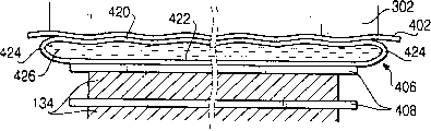
图10是图9中所示是压机的一部分的垂直剖面图,示出了将一组印刷电路板进行压制的垫层构件;Figure 10 is a vertical sectional view of a portion of the press shown in Figure 9, showing a mat member for pressing a set of printed circuit boards;
图11是图10中所示压机一部分的垂直剖面图,示出了图10中的垫层构件的改变。FIG. 11 is a vertical section view of a portion of the press shown in FIG. 10 showing a modification of the mat member in FIG. 10. FIG.
具体实施方式Detailed ways
下面,将参考相关附图描述本发明的实施例。Hereinafter, embodiments of the present invention will be described with reference to related drawings.
(第一实施例)(first embodiment)
图1示意的是按照本发明第一实施例的压制设备100的结构图。FIG. 1 schematically shows a structural view of a pressing apparatus 100 according to a first embodiment of the present invention.
压制设备100包括安装在框架104的顶板104a上的活塞-汽缸机构102。活塞-汽缸机构102包括汽缸106和位于汽缸106内并且沿汽缸106的内壁上下延伸的活塞108。在汽缸106的底部开有通孔112。活塞杆110安装在活塞108的底部,与活塞108一起上下移动。The pressing apparatus 100 includes a piston-cylinder mechanism 102 mounted on a top plate 104 a of a frame 104 . The piston-cylinder mechanism 102 includes a cylinder 106 and a piston 108 located within the cylinder 106 and extending up and down the inner wall of the cylinder 106 . A through hole 112 is opened at the bottom of the cylinder 106 . The piston rod 110 is mounted on the bottom of the piston 108 and moves up and down together with the piston 108 .
汽缸106的内部空间被活塞108分成上部空间106a和下部空间106b。上部空间106a和下部空间106b内均填充有液压油。上部和下部空间106a,106b与液压泵210相连,液压泵210在控制器170的控制下驱动。液压泵210能够将上部或者下部空间106a,106b之一中的液压油的压力提高,而将另一个压力降低,从而推动活塞108上下运动。The internal space of the cylinder 106 is divided into an upper space 106a and a lower space 106b by the piston 108 . Both the upper space 106a and the lower space 106b are filled with hydraulic oil. The upper and lower spaces 106 a , 106 b are connected to a
活动台114固定到活塞杆110的下端,由活塞-汽缸机构102产生的压力推动而上下运动。上部加热台板116还固定到带有热绝缘器118的活动台114的下表面。热绝缘器118能够防止上部加热台板116由于从上部加热台板116朝向活动台114的热传导而产生的热量损失。加热台板116的下表面覆盖有上部台板盖120。The movable table 114 is fixed to the lower end of the piston rod 110 and is pushed up and down by the pressure generated by the piston-cylinder mechanism 102 . The upper
固定台122安装在框架104的底板104b上,下部加热台板124安装在固定台122上,固定台122带有用于防止位于其间的下部加热台板124的热量损失的热绝缘器126。下部加热台板124的上表面覆盖有下部台板盖128。A fixed table 122 is mounted on the bottom plate 104b of the frame 104, and a
一个或者多个工件,例如印刷电路板,可以将铜敷箔叠压板或者类似物放置于下部台板盖128上用于压制。在本实施例中,将具有两层电路层和位于两层电路层之间的一层半固化片层的印刷电路板134放置于下部台板盖128上。电路层和半固化片层的厚度分别为18μm和50μm。因此,印刷电路板134的总厚度为86μm。One or more workpieces, such as printed circuit boards, may have a copper-clad foil laminate or the like placed on the lower deck cover 128 for pressing. In this embodiment, a printed
上部和下部加热台板116,124与泵130相连,泵130将加热媒介例如热传导油输送到随后即将描述的每个加热台板(116,124)中。在泵130和两块台板116和124之间布置加热器132,用于对热传导油进行加热。The upper and lower
由泵130供给的热传导油由加热器132进行加热,然后流经上部和下部加热台板116,124。这样,上部和下部加热台板116,124就被加热到预定成型温度,该温度要求能够将印刷电路板134的半固化片层加热到一个半固化片基本上为液体的温度。Heat transfer oil supplied by pump 130 is heated by heater 132 and then flows through upper and lower heated platens 116,124. Thus, the upper and lower
如果加热台板116及固定于其上的活动台114受到活塞-汽缸机构102向下的作用,那么位于下部台板盖128上的印刷电路板134在上部和下部台板盖120和128之间就呈三明治式的夹层结构。夹层结构的印刷电路板134由上部和下部台板盖120,128进行加热和加压。结果,电路层就能够由半固化片层很坚固地粘结,印刷电路板134就会形成均匀的厚度。If the
图2所示的是上部加热台板116的水平剖面图。上部加热台板116是一块由钢板制成的厚板,基本上呈方形。在上部加热台板116上形成有第1至第11个通孔140-160。FIG. 2 is a horizontal cross-sectional view of the upper
沿图2中的上下方向彼此相互平行地形成第1至第8通孔140-154。另一方面,沿图2中的横向形成第9至第11通孔156-160。尤其是,第9通孔156是在靠近图2中的上部加热台板116的下端形成,因此它就与第1至第8通孔140-154相交成直角。而且,第10通孔158是在靠近上部加热台板116的顶端从左侧向上到第6通孔150进行钻孔的。第11通孔160也是在靠近上部加热台板116的顶端从右侧向上到第7通孔152进行钻孔的。The first to eighth through
用多个钢坯帽162将通孔140-160堵死,因此在上部加热台板116中就形成一个加热管道164,该管道从第1通孔140的一端140a开始,弯曲通过上部加热台板116,在第8通孔154的另一端154a终止,正如图2中的折断线A所示。The through-holes 140-160 are blocked by a plurality of billet caps 162, so that a
由泵130供给的热传导油流经加热导管164以便对上部加热台板116进行加热。上部加热台板116带有与控制器170(见图1)相连的热传感器(图中未示出)。控制器170基于由热传感器探测到的温度对加热器132进行控制,从而调整流经加热导管164的热传导油的温度,以便将上部加热台板116加热到预定的温度,例如本实施例中半固化片的温度为200°。Heat transfer oil supplied by pump 130 flows through
在上部加热台板116的周边沿垂直于图2中的方向形成有多个通孔172。通过将螺栓拧入通孔172中将上部台板盖120安装在上部加热台板116的下表面,通孔172将在随后进行描述。A plurality of through
上部加热台板116还带有两个孔180和182。孔180在第6通孔150和第7通孔152之间从图2中的上部加热台板116的上端平行于第6通孔150的方向进行钻孔。孔182从上部加热台板116的下表面进行钻孔,与孔180成直角。两个孔180和182构成压力管道184,压力管道184从侧面向上部加热台板116的下表面进行延伸。The upper
图3是上部加热台板116和固定于其上的上部台板盖120的沿图2中的I-I线的剖面图。FIG. 3 is a cross-sectional view of the upper
上部台板盖120包括矩形形状的环形框架190和金属板194。框架190和金属板194都是由具有导热性能很高的材料制成。The upper deck cover 120 includes a rectangular shaped
沿框架190的底部周边形成翼缘192。翼缘192从框架190向外延伸,基本上平行于框架190的下表面。金属板194是由表面经过镜面加工的不锈钢制成的薄板。A flange 192 is formed along the bottom periphery of the
金属板194和翼缘192以一种水密性的方式沿其周边彼此相互焊接。这样,金属板194和框架190就形成为一个工件。The metal plate 194 and the flange 192 are welded to each other along their peripheries in a watertight manner. Thus, the metal plate 194 and the
框架190具有多个从上表面垂直钻通的螺栓孔196(图3中只示出一个)。这些螺栓孔196用来将上部台板盖120通过螺栓198固定到上部加热台板116上,螺栓198将在随后进行描述。The
上部加热台板116在其底端具有突出部116a,环绕突出部116a具有肩部116b。形成突出部116a的作用是为了与上部台板盖120的框架190紧密配合。突出部116a可以一直插入到框架190的上表面并与上部加热台板116的肩部116b进行对接。肩部116b能够限制插入到框架190中的突出部116a的长度,以便在上部加热台板116的下表面和金属板194之间形成空间200。The upper
在肩部116b上开有凹槽116d,框架190的上部固定于其中。通过将框架190固定到凹槽116d中,可以调整框架190和上部加热台板116之间的相对位置,以便使上部加热台板116的每一个通孔172都能够分别与框架190的螺栓孔196相对应。这样,就能够通过将螺栓198固定到每个通孔172中并且拧入相应的螺栓孔196中,而将上部台板盖120固定到上部加热台板116上。A groove 116d is formed in the shoulder 116b into which the upper portion of the
在上部加热台板116的下表面116c,或者压制表面和金属板194之间形成的空间200与压力管道184相连通。空间200和压力管道184内填充有热传导油,能够将热量从上部加热台板116传递给金属板194。由于热传导油具有较高的导热性能,因此金属板194的温度基本上与上部加热台板116的温度相同。The
压力管道184的一端186与压力发生器202(见图1)相连,压力发生器202在控制器170的控制之下,能够改变填充到空间200中的热传导油的压力。在框架190的上表面和上部加热台板116的凹槽116d之间设有填充物204,即使当压力发生器202已经向热传导油加压时,也能防止热传导油从空间200向外泄漏。One end 186 of the
应当注意,下部加热台板124和下部台板盖128的结构和功能分别基本上与上部加热台板116和上部台板盖120的结构和功能相同。因此,上面关于上部加热台板116和上部台板盖120的描述也同样适用于下部加热台板124和下部台板盖128。It should be noted that the structure and function of the lower
下面,将参考附图4A至4C描述由压制设备100对印刷电路板134进行压制的过程。Next, a process of pressing the printed
首先,如图4A所示,将一个或者多个隔板210放在框架190的下部台板盖128的金属板194上。隔板的高度h略大于印刷电路板134的厚度t。First, one or
随后,开动压制设备100的泵130和加热器132,热油流经在上部和下部加热台板116和124中形成的加热管道164。对热传导油的温度进行控制,以便使上部和下部加热台板116,124的温度保持在预定的温度。Subsequently, the pump 130 and the heater 132 of the pressing apparatus 100 are activated, and hot oil flows through the
上部加热台板116的热量通过填充到空间200中的热传导油被传递到上部台板盖120。因此,上部台板盖120也被加热到一定的温度。安装到下部加热台板124上的下部台板盖128也按上面描述的方式进行加热。The heat of the
通过温度传感器(图中未示出)对上部和下部加热台板116和124的温度进行测量。当确认上部和下部加热台板116和124已经被加热到预定的温度时,将印刷电路板132放置于下部台板盖128上。The temperature of the upper and lower
然后,开动活塞-汽缸机构102对安装于其上的上部加热台板116和上部台板盖120沿朝向印刷电路板134的方向施加压力。因此,上部加热台板116和上部压板盖120就开始移动直到上部台板盖120压制隔板210为止,如图4B所示。Then, the piston-cylinder mechanism 102 is actuated to apply pressure in a direction toward the printed
隔板210与框架190的上部台板盖120进行对接,从而能够支承上部台板盖和上部加热台板116,这样在印刷电路板134和上部台板盖120的金属板194之间就形成一定间距。The
然后,将填充在上部加热台板130和上部台板盖140之间的热传导油和填充在下部加热台板124和下部压板盖128之间的热传导油通过压力发生器202进行加压,使之达到预定的压力数值。该预定的压力数值不能大于加热台板所能够承受的最大压力值。这样,经过加压的热传导油就不会将加热台板从隔板上推走。Then, the heat transfer oil filled between the upper heating platen 130 and the
当对热传导油进行加压时,上部和下部台板盖120,128的金属板194会沿朝向印刷电路板134的方向进行轻微地弯曲,如图4C所示。然而,每块金属板194的弯曲都是受将隔板210进行压制的上部和下部加热台板116,124之间的距离限制的。因此,金属板194就不会由于过度的弯曲而发生破坏。When the heat transfer oil is pressurized, the metal plates 194 of the upper and lower deck covers 120, 128 bend slightly in a direction toward the printed
已经弯曲的两块金属板194将印刷电路板134进行压制并且形成夹层结构。由金属薄板形成的金属板194由于受到热传导油的压力而沿印刷电路板134的表面进行弯曲,从而对整个印刷电路板134施加均匀的压力。另外,由于印刷电路板134的两侧是按同样大小和均匀的压力进行压制的,因此,印刷电路板134和压制印刷电路板的金属板194在整个压制过程中基本上变得很平。The two metal plates 194 that have been bent press the printed
而且,由于金属板194的表面是经过镜面加工的表面,因此在压制过程中不会形成任何瑕疵。Also, since the surface of the metal plate 194 is a mirror-finished surface, no flaws are formed during the pressing process.
压制设备100将上述状态保持一段时间,足以使电路层与半固化片层相互粘结。然后,压力发生器202将上部/下部加热台板(116,124)和上部/下部台板盖(120,128)之间的热传导油的压力进行减压。这样,金属板194又回到一种基本上很平的状态,如图4B所示。然后,将活动台114向上驱动,使上部台板盖120远离下部台板盖128,以便将印刷电路板134移走。The pressing device 100 maintains the above state for a period of time sufficient for the circuit layer and the prepreg layer to be bonded to each other. The pressure generator 202 then reduces the pressure of the heat transfer oil between the upper/lower heating platens (116, 124) and the upper/lower platen covers (120, 128). Thus, the metal plate 194 returns to a substantially flat state, as shown in FIG. 4B. The movable table 114 is then driven upwardly to move the upper deck cover 120 away from the lower deck cover 128 to remove the printed
如上所述,当上部加热台板116被压制到抵抗隔板210以便在印刷电路板134和上部加热台板116的金属板194之间限定出一个较小的间隙时,将填充在上部/下部加热台板(116,124)和上部/下部台板盖(120,128)之间的热传导油加压到预定的压力数值。这样,按照本实施例的压制设备100就能够防止上部和下部台板盖120,128的金属板194由于对热传导油施加较高的压力而产生过大的弯曲和破坏。As described above, when the upper
(第二实施例)(second embodiment)
下面,将描述按照本发明第二实施例的压制设备。应当注意,在本实施例和下面的实施例中,那些与第一实施例中描述的构件基本相同的构件仍采用相同的附图标记来表示。Next, a pressing apparatus according to a second embodiment of the present invention will be described. It should be noted that in this embodiment and the following embodiments, those components that are substantially the same as those described in the first embodiment are still denoted by the same reference numerals.
图5示出的是按照本发明第二实施例的压制设备300的结构。按照本发明第二实施例的压制设备300的结构和操作过程与第一实施例相同,除上部和下部加热台板302,304和上部和下部台板盖306,308的结构不同之外。特别是,上部和下部台板盖306,308与第一实施例中的不同之处在于它们还包括垫板310而不是框架190。FIG. 5 shows the structure of a pressing apparatus 300 according to a second embodiment of the present invention. The structure and operation of the pressing apparatus 300 according to the second embodiment of the present invention are the same as those of the first embodiment, except that the structures of upper and
图6是示于图5中的压制设备300的上部加热台板302的水平剖面图。图6中的上部加热台板302不同于图2中的上部加热台板116之处,在于它没有任何与压力管道184相对应的管道。除了上述不同之外,图5中的上部加热台板302的结构与图2中的上部加热台板116的结构相同。FIG. 6 is a horizontal sectional view of the
图7是上部台板盖306的水平剖面图,示出了垫板310的下表面,图8是安装在上部加热台板302上的上部台板盖306的沿图7中的II-II线的垂直剖面图。FIG. 7 is a horizontal cross-sectional view of the
正如图8中所看到的,垫板310是一块具有上表面312和下表面314的厚金属板。在下表面314附近沿垫板310的周边形成翼缘320。翼缘320的边缘与金属板194的边缘相焊接,以便金属板194的上表面与垫板310的下表面正常接触。As seen in FIG. 8 , the
在垫板310的上表面上,与上部加热台板302上形成的通孔172相应的位置处,形成多个螺栓孔(图中未示出)。通过穿过通孔172然后拧入螺栓孔的螺栓(未示出)将垫板310固定到上部加热台板302上。当垫板310固定到上部加热台板302上时,垫板310的上表面312就与上部加热台板的下表面相接触。因此,上部加热台板302就能够对垫板310有效地进行加热。A plurality of bolt holes (not shown) are formed on the upper surface of the
如图7所示,垫板310的下表面312上开有格栅形式并且基本上遍布整个下表面312的凹槽322,。在垫板310上还形成有压力管道324,该压力管道324将凹槽322与垫板310一侧的开孔326相连(见图8)。As shown in FIG. 7 , the
通过在垫板310的侧面上形成的开孔326将压力管道324与压力发生器202(见图5)相连接。压力发生器202通过压力管道324将热传导油供给格栅状凹槽322,并且还能对其油压进行控制。The
由于金属板194通常是与垫板310的下表面相连,在它们之间除了凹槽322外没有任何空间,因此,通过压力管道324供给的热传导油主要流向凹槽322,从而能够迅速遍布金属板194。Since the metal plate 194 is usually connected to the lower surface of the
压力管道324包括四个从垫板310的下表面312钻通的垂直孔330。压力管道324还包括与这四个垂直孔330和从在垫板310侧形成的开孔326延伸的横向孔334相连接的环形部分332。四个垂直孔330在与格栅状凹槽322的最外角相应的位置处形成,以便供给凹槽322的热传导油能够迅速和均匀地遍布整个凹槽322。The
当热传导油流遍凹槽322之后,如果压力发生器202向热传导油施加压力的话,受压后的热传导油就将金属板194向下压,将其压离垫板310的下表面312,并且填充金属板194和垫板310之间出现的空间。因此,在金属板194和垫板310之间就形成了热传导油的液体层,它对金属板194施加均匀的压力。After the heat transfer oil flows through the
应当注意,按照本实施例的压制设备300没有任何从上部加热台板302向上部台板盖306延伸的管道。因此,按照本实施例的压制设备300很少有漏油的危险,并且上部台板盖306能够很容易地从上部加热台板302上进行安装或者拆卸,因为在它们之间不必插入任何填充物。It should be noted that the pressing apparatus 300 according to this embodiment does not have any ducts extending from the upper
还应当注意,下部加热台板304和下部台板盖308的结构和功能基本上分别与上部加热台板302和上部台板盖306类似。因此,上面描述的有关上部加热台板302和上部台板盖306的结构和功能也同样适用于下部加热台板304和下部台板盖308。It should also be noted that the lower heated platen 304 and lower platen cover 308 are substantially similar in structure and function to the upper
(第三实施例)(third embodiment)
图9简要示出了根据本发明第三实施例的压制设备400的结构,它是本发明第二实施例的压制设备300的改进。FIG. 9 schematically shows the structure of a pressing device 400 according to a third embodiment of the present invention, which is a modification of the pressing device 300 of the second embodiment of the present invention.
根据第三实施例的压制设备400不同于第二实施例的压制设备300之处在于上部加热台板302的下表面和下部加热台板304的上表面分别由顶板402和承运板404覆盖,而不是由上部和下部台板盖306,308覆盖,它们都是由不锈钢制成。还有,根据第三实施例的压制设备400包括两个垫层构件406和一块或者多块中间板408。每块中间板都是由不锈钢制成,并具有镜面抛光表面,其粗糙度在几微米之内。除了上面所述的不同之外,根据第三实施例的压制设备400基本上与第二实施例中的压制设备300相同。The pressing apparatus 400 according to the third embodiment is different from the pressing apparatus 300 of the second embodiment in that the lower surface of the
按照本发明的第三实施例,多个印刷电路板134和多个中间板408彼此交替堆放,以便在两块中间板之间的印刷电路板134为三明治式的夹层结构。然后,将印刷电路板134和中间板408的叠层组堆放置于顶板402和承运板404之间,目的是通过一个压制操作同时对其进行压制。According to the third embodiment of the present invention, the plurality of printed
将一个垫层构件406放置于顶板402和最上面的中间板408之间,而将其他垫层构件406放置于承运板404和最下面的中间板408之间。但是,在本实施例中,在加热台板302,304之间不设隔板。按照上面方式放置的垫层构件408取消,在压制过程中,在印刷电路板134上的顶板402和承运板404的表面起伏和倾斜情况将在下面进行描述。One
图10是图9中所示的压制设备400中的一部分的垂直剖面图,示出了将印刷电路板134叠层组进行压制的垫层构件406。垫层构件406具有第一和第二金属板420,422。第一和第二金属板420和422均由不锈钢制成,例如其表面为镜面抛光表面。第一和第二金属板420,422彼此平行地布置,彼此通过将端部424沿周边进行焊接而相互连接,以便使它们之间的空间426从外部密封。用热传导油填充上面所密封出的空间426,以在第一和第二块板420,422之间形成液体层。FIG. 10 is a vertical cross-sectional view of a portion of the pressing apparatus 400 shown in FIG. 9, showing the
通过按照上面所布置的垫层构件406,将来自顶板402的压力施加于液体层,然后施加到第二金属板422。由于在连续的液体层内的压力大小在任何位置都相同,因此,即使与垫层构件406相连的顶板402有不均匀或者倾斜,液体层仍然能够将均匀的压力施加到第二块金属板422上。The pressure from the
反过来,第二块金属板422对最上面的中间板408施加均匀的压力。同样,放置在下部加热台板304和印刷电路板134叠层组之间的另一块垫层构件406对最下部的中间板408施加均匀的压力。因此,每一块印刷电路板134都是用均匀的压力进行压制的。这样,印刷电路板134叠层组及其中的每一块印刷电路板134的厚度是均匀的,沿整个电路板,电路层与半固化片层就能够紧紧地相粘结。In turn, the
应当注意,垫层构件406的第二块金属板422和中间板408分别是由薄的金属板制成,以便它们能够沿印刷电路板134的表面进行弯曲,从而能够确保压力均匀地施加给印刷电路板134。It should be noted that the
还应当注意,垫层构件406不会干扰热量从上部和下部加热台板302,304传递到印刷电路板134叠层组,因为垫层构件406内填充有热传导油,它具有很高的导热性能。因此,按照本实施例的用于压制印刷电路板134的压制设备400不需要加热很长时间。It should also be noted that the
图11是图10中所示压机400的一部分的垂直剖面图,示出了图10中的垫层构件的改变。FIG. 11 is a vertical cross-sectional view of a portion of the press 400 shown in FIG. 10 showing a modification of the mat member in FIG. 10 .
图11所示的垫层构件406包括两块金属板432,434,例如不锈钢板,它们彼此平行布置。将一环形框架436放置于两块金属板432,434之间,以便使它们以预定的距离(例如几毫米)彼此保持平行。The
将框架436与两块金属板432,434沿整个上边缘和下边缘焊接,以便将两块金属板432,434内限定的空间440及框架436从外部进行密封。该空间440内填充有热传导油,以便在两块金属板之间形成液体层。The frame 436 is welded to the two metal plates 432, 434 along the entire upper and lower edges to seal the space 440 defined in the two metal plates 432, 434 and the frame 436 from the outside. The space 440 is filled with heat transfer oil to form a liquid layer between the two metal plates.
液体层消除了压制垫层构件430的顶板402的表面不平整和/或倾斜,以便图11中的垫层构件430对最上面的中间板408施加均匀的压力,就如图10中的垫层构件402。液体层还能够实现垫层构件430的极好的热传导性。因此,图11中的垫层构件在压制过程中不会妨碍印刷电路板134叠层组的有效加热。The liquid layer eliminates surface irregularities and/or inclinations of the
应当注意,示于图10中的垫层构件406的第二块金属板422仅能在其中心周围很小的范围内对中间板408施加均匀的压力,由于接近边缘的区域与第一金属板的边缘焊接,该区域会向上的弯曲,如图10所示。然而,示于图11中的垫层构件430的第二块板434就能够在很大面积范围内对中间板408施加均匀的压力,这是因为框架436能够使第二块金属板432基本上保持很平。It should be noted that the
Claims (31)
Applications Claiming Priority (6)
| Application Number | Priority Date | Filing Date | Title |
|---|---|---|---|
| JP2001263911 | 2001-08-31 | ||
| JP2001263911 | 2001-08-31 | ||
| JP2002029479 | 2002-02-06 | ||
| JP2002029479A JP3847633B2 (en) | 2001-08-31 | 2002-02-06 | Press apparatus and press method |
| JP2002124290 | 2002-04-25 | ||
| JP2002124290A JP2003311494A (en) | 2002-04-25 | 2002-04-25 | Press device and cushion member for press device |
Related Child Applications (1)
| Application Number | Title | Priority Date | Filing Date |
|---|---|---|---|
| CN2006101714733A Division CN1982043B (en) | 2001-08-31 | 2002-08-30 | Device for pressing workpiece |
Publications (2)
| Publication Number | Publication Date |
|---|---|
| CN1406743A true CN1406743A (en) | 2003-04-02 |
| CN100410066C CN100410066C (en) | 2008-08-13 |
Family
ID=27347413
Family Applications (2)
| Application Number | Title | Priority Date | Filing Date |
|---|---|---|---|
| CNB021414645A Expired - Fee Related CN100410066C (en) | 2001-08-31 | 2002-08-30 | Device for pressing workpieces |
| CN2006101714733A Expired - Fee Related CN1982043B (en) | 2001-08-31 | 2002-08-30 | Device for pressing workpiece |
Family Applications After (1)
| Application Number | Title | Priority Date | Filing Date |
|---|---|---|---|
| CN2006101714733A Expired - Fee Related CN1982043B (en) | 2001-08-31 | 2002-08-30 | Device for pressing workpiece |
Country Status (7)
| Country | Link |
|---|---|
| US (1) | US6779703B2 (en) |
| EP (1) | EP1293271B1 (en) |
| KR (1) | KR100750582B1 (en) |
| CN (2) | CN100410066C (en) |
| DE (1) | DE60225643T2 (en) |
| SG (1) | SG111082A1 (en) |
| TW (1) | TW583073B (en) |
Cited By (12)
| Publication number | Priority date | Publication date | Assignee | Title |
|---|---|---|---|---|
| CN100445085C (en) * | 2004-04-16 | 2008-12-24 | 北川精机株式会社 | Presses and press systems |
| CN101054003B (en) * | 2006-04-14 | 2010-05-26 | 本田技研工业株式会社 | Press processing method and press processing equipment |
| US7802597B2 (en) | 2005-03-25 | 2010-09-28 | Kitagawa Seiki Kabushiki Kaisha | Press apparatus |
| CN101905529A (en) * | 2009-05-14 | 2010-12-08 | 北川精机株式会社 | Pressing device |
| CN101982999A (en) * | 2010-09-29 | 2011-03-02 | 卓盈微电子(昆山)有限公司 | Flexible circuit board heating table |
| CN102159388A (en) * | 2008-07-22 | 2011-08-17 | 亨特道格拉斯工业公司 | Efficient lamination press with flexible platens |
| CN102490388A (en) * | 2011-12-18 | 2012-06-13 | 青岛雷尔威机械制造有限公司 | Heating unit used for pressurized equipment |
| CN102596552A (en) * | 2009-10-09 | 2012-07-18 | 马尔照片夹层玻璃有限公司 | Device and method for producing laminated safety glass |
| CN104275910A (en) * | 2013-07-10 | 2015-01-14 | 北川精机株式会社 | Protective plate and support plate for pressure molding, and pressure molding device |
| CN105587694A (en) * | 2016-02-29 | 2016-05-18 | 湖州佳宁印刷有限公司 | Pressing hydraulic system of decoration printing paper manufacturing system |
| CN105626603A (en) * | 2016-02-29 | 2016-06-01 | 湖州佳宁印刷有限公司 | Decorative printing paper making system |
| CN108235604A (en) * | 2018-01-11 | 2018-06-29 | 广合科技(广州)有限公司 | PCB presses material temperature automatic control system and its control method |
Families Citing this family (31)
| Publication number | Priority date | Publication date | Assignee | Title |
|---|---|---|---|---|
| US7441688B2 (en) * | 2003-11-04 | 2008-10-28 | Reactive Nanotechnologies | Methods and device for controlling pressure in reactive multilayer joining and resulting product |
| DE60225643T2 (en) * | 2001-08-31 | 2008-06-26 | Kitagawa Seiki K.K., Fuchu | Method and device for hot pressing a workpiece |
| EP1712347A1 (en) * | 2004-02-04 | 2006-10-18 | Sumitomo Heavy Industries, Ltd. | Pressing/molding apparatus, mold, and pressing/molding method |
| US20060003548A1 (en) * | 2004-06-30 | 2006-01-05 | Kobrinsky Mauro J | Highly compliant plate for wafer bonding |
| EP1803549A1 (en) * | 2005-12-30 | 2007-07-04 | Robert Bürkle GmbH | Heating plate for platen press |
| GB2461114A (en) * | 2008-03-01 | 2009-12-30 | Tradewise Engineering Ltd | Punching Apparatus with temperature control means |
| US9199439B2 (en) | 2008-07-22 | 2015-12-01 | 3Form, Llc | Efficient lamination press with thin flexible platens |
| KR100913811B1 (en) * | 2008-12-29 | 2009-08-26 | 주식회사 세지솔로텍 | Real Wood Film, Manufacturing Method and Molded Products Using Real Wood Film |
| JP2010207902A (en) * | 2009-03-12 | 2010-09-24 | Kitagawa Elaborate Mach Co Ltd | Vacuum press apparatus and vacuum press method |
| CN102131349B (en) * | 2010-01-14 | 2013-10-16 | 富葵精密组件(深圳)有限公司 | Rolling device and method for rolling circuit board |
| DE102010036539B4 (en) * | 2010-07-21 | 2013-04-11 | Hueck Rheinische Gmbh | Press pad for a hydraulic press |
| RU2492052C1 (en) * | 2012-03-02 | 2013-09-10 | Общество с ограниченной ответственностью "БЛИЗНЕЦЫ" | Heating board |
| JP6172654B2 (en) * | 2013-03-14 | 2017-08-02 | アルファーデザイン株式会社 | Component pressing device and heating system using the component pressing device |
| EP4230337A3 (en) | 2013-12-18 | 2023-11-15 | Aster Co., Ltd. | An apparatus for manufacturing a coil and a coil manufacturing method |
| JP5592554B1 (en) | 2013-12-18 | 2014-09-17 | 武延 本郷 | Cold welding apparatus, coil manufacturing apparatus, coil and manufacturing method thereof |
| KR20160048301A (en) * | 2014-10-23 | 2016-05-04 | 삼성전자주식회사 | bonding apparatus and substrate manufacturing equipment including the same |
| CN104494181A (en) * | 2014-12-10 | 2015-04-08 | 南京工程学院 | Film type small-strokepressure machine |
| DE102015014512B4 (en) * | 2015-11-11 | 2017-05-24 | Fraunhofer-Gesellschaft zur Förderung der angewandten Forschung e.V. | Method and device for the consolidation of impregnated fiber composite structures |
| KR101758478B1 (en) * | 2015-12-14 | 2017-07-17 | 주식회사 포스코 | Apparatus for processing material |
| CN106827559A (en) * | 2017-03-22 | 2017-06-13 | 江苏汤臣新材料科技有限公司 | A kind of lucite shrinks splicing apparatus |
| CN108296366A (en) * | 2018-02-12 | 2018-07-20 | 莱特伟特(苏州)汽配科技有限公司 | A kind of uniform thin plate direct-electrifying heating device of temperature |
| CN108454215A (en) * | 2018-04-30 | 2018-08-28 | 北京博简复才技术咨询有限公司 | A kind of sandwich structure production equipment and process |
| US11152328B2 (en) * | 2018-12-13 | 2021-10-19 | eLux, Inc. | System and method for uniform pressure gang bonding |
| CN113141679B (en) * | 2020-01-17 | 2022-05-17 | 昆山哈工万洲焊接研究院有限公司 | Method and device for improving resistance heating temperature uniformity of metal plate by utilizing gallium |
| US11884426B2 (en) * | 2020-07-08 | 2024-01-30 | Hamilton Sundstrand Corporation | Compression apparatus and methods of making and using the same |
| CN113146771B (en) * | 2021-06-01 | 2022-04-19 | 南平市华泰木竹有限公司 | Efficient and energy-saving veneer drying process method |
| CN114122310A (en) * | 2021-11-25 | 2022-03-01 | 遂宁市天莱新能源科技有限公司 | Pole piece tabletting equipment for lithium battery production |
| US20250058539A1 (en) * | 2021-12-20 | 2025-02-20 | Kool Global Solutions Pty Ltd | Apparatus for forming a blank |
| CN114340229B (en) * | 2022-01-25 | 2022-08-16 | 益阳市明正宏电子有限公司 | Quick compression fittings based on 5G optical module PCB |
| CN115334781B (en) * | 2022-07-22 | 2024-11-01 | 珠海市隆顺电子科技有限公司 | Anti-dislocation type lamination equipment for processing multilayer circuit board |
| WO2024086748A2 (en) * | 2022-10-19 | 2024-04-25 | Alloy Enterprises Inc. | Manufacturing large scale metal laminated object parts |
Family Cites Families (21)
| Publication number | Priority date | Publication date | Assignee | Title |
|---|---|---|---|---|
| GB1270110A (en) * | 1968-08-05 | 1972-04-12 | Ici Ltd | Improvements in or relating to pressing processes |
| US3806104A (en) * | 1969-11-06 | 1974-04-23 | Ici Ltd | Presses |
| US4049184A (en) * | 1976-06-07 | 1977-09-20 | Jury Iosifovich Rozengart | Method of manufacturing polymetallic pipes |
| US4216874A (en) * | 1977-06-27 | 1980-08-12 | Kiwa Torisu | Weld assembled tank |
| DE2904067A1 (en) * | 1979-02-03 | 1980-12-18 | Friz Helmut Dipl Ing | MOLD PRESS |
| FR2587273B1 (en) * | 1985-09-19 | 1988-04-08 | Darragon Sa | METHOD AND AUTOCLAVE PRESSURE FOR LAMINATING MULTI-LAYER PRINTED CIRCUITS AND / OR PLASTIFICATION OF FLAT ELEMENTS, AND DEVICE FOR CONVERTING INTO AUTOCLAVE PRESS OF THIS TYPE |
| US4691857A (en) * | 1985-11-07 | 1987-09-08 | Trw Inc. | Method of shaping a workpiece |
| US5016805A (en) * | 1988-10-31 | 1991-05-21 | Rohr Industries, Inc. | Method and apparatus for dual superplastic forming of metal sheets |
| JPH0647600A (en) * | 1991-07-15 | 1994-02-22 | Masashi Shishido | Pressing/heating plate for pressing machine |
| JP2839215B2 (en) * | 1991-09-04 | 1998-12-16 | 株式会社カイジョー | Bonding equipment |
| CN2144571Y (en) * | 1992-09-09 | 1993-10-27 | 王仁川 | Hand-operated hydraulic press |
| JPH07195391A (en) * | 1993-12-28 | 1995-08-01 | Hitachi Techno Eng Co Ltd | hot press |
| US5529238A (en) * | 1994-09-20 | 1996-06-25 | Xerox Corporation | Gold to gold substrate bonding system utilizing interferometric planarization feedback |
| US5890285A (en) * | 1996-08-23 | 1999-04-06 | Mcdonnell Douglas Corporation | Method for superplastically forming a structural article |
| US6706406B1 (en) * | 1996-11-13 | 2004-03-16 | Fern Investments Limited | Composite steel structural plastic sandwich plate systems |
| JP3359540B2 (en) * | 1997-06-27 | 2002-12-24 | 京セラ株式会社 | Method for manufacturing multilayer printed wiring board |
| US5941866A (en) * | 1997-07-25 | 1999-08-24 | Bracco Research Usa | Means to maintain configuration of flexible medical container |
| US6264880B1 (en) * | 1998-07-22 | 2001-07-24 | The Regents Of The University Of California | Manifold free multiple sheet superplastic forming |
| JP3098003B2 (en) * | 1998-09-24 | 2000-10-10 | 日清紡績株式会社 | Laminating equipment for solar cells |
| DE60225643T2 (en) * | 2001-08-31 | 2008-06-26 | Kitagawa Seiki K.K., Fuchu | Method and device for hot pressing a workpiece |
| JP4175819B2 (en) * | 2002-03-11 | 2008-11-05 | 北川精機株式会社 | Press device and control method of press device |
-
2002
- 2002-08-29 DE DE60225643T patent/DE60225643T2/en not_active Expired - Lifetime
- 2002-08-29 SG SG200205255A patent/SG111082A1/en unknown
- 2002-08-29 EP EP02256002A patent/EP1293271B1/en not_active Expired - Lifetime
- 2002-08-29 KR KR1020020051380A patent/KR100750582B1/en not_active Expired - Fee Related
- 2002-08-30 TW TW091119847A patent/TW583073B/en not_active IP Right Cessation
- 2002-08-30 CN CNB021414645A patent/CN100410066C/en not_active Expired - Fee Related
- 2002-08-30 CN CN2006101714733A patent/CN1982043B/en not_active Expired - Fee Related
- 2002-08-30 US US10/232,318 patent/US6779703B2/en not_active Expired - Fee Related
Cited By (16)
| Publication number | Priority date | Publication date | Assignee | Title |
|---|---|---|---|---|
| CN100445085C (en) * | 2004-04-16 | 2008-12-24 | 北川精机株式会社 | Presses and press systems |
| US7802597B2 (en) | 2005-03-25 | 2010-09-28 | Kitagawa Seiki Kabushiki Kaisha | Press apparatus |
| CN101146671B (en) * | 2005-03-25 | 2010-12-15 | 北川精机株式会社 | Stamping device |
| CN101054003B (en) * | 2006-04-14 | 2010-05-26 | 本田技研工业株式会社 | Press processing method and press processing equipment |
| CN102159388A (en) * | 2008-07-22 | 2011-08-17 | 亨特道格拉斯工业公司 | Efficient lamination press with flexible platens |
| CN101905529A (en) * | 2009-05-14 | 2010-12-08 | 北川精机株式会社 | Pressing device |
| CN101905529B (en) * | 2009-05-14 | 2014-12-17 | 北川精机株式会社 | Pressure device |
| CN102596552A (en) * | 2009-10-09 | 2012-07-18 | 马尔照片夹层玻璃有限公司 | Device and method for producing laminated safety glass |
| CN102596552B (en) * | 2009-10-09 | 2015-04-29 | 马尔照片夹层玻璃有限公司 | Device and method for producing laminated safety glass |
| US9242434B2 (en) | 2009-10-09 | 2016-01-26 | Fotoverbundglas Marl Gmbh | Device and method for producing laminated safety glass |
| CN101982999A (en) * | 2010-09-29 | 2011-03-02 | 卓盈微电子(昆山)有限公司 | Flexible circuit board heating table |
| CN102490388A (en) * | 2011-12-18 | 2012-06-13 | 青岛雷尔威机械制造有限公司 | Heating unit used for pressurized equipment |
| CN104275910A (en) * | 2013-07-10 | 2015-01-14 | 北川精机株式会社 | Protective plate and support plate for pressure molding, and pressure molding device |
| CN105587694A (en) * | 2016-02-29 | 2016-05-18 | 湖州佳宁印刷有限公司 | Pressing hydraulic system of decoration printing paper manufacturing system |
| CN105626603A (en) * | 2016-02-29 | 2016-06-01 | 湖州佳宁印刷有限公司 | Decorative printing paper making system |
| CN108235604A (en) * | 2018-01-11 | 2018-06-29 | 广合科技(广州)有限公司 | PCB presses material temperature automatic control system and its control method |
Also Published As
| Publication number | Publication date |
|---|---|
| US6779703B2 (en) | 2004-08-24 |
| EP1293271A2 (en) | 2003-03-19 |
| EP1293271B1 (en) | 2008-03-19 |
| TW583073B (en) | 2004-04-11 |
| EP1293271A3 (en) | 2004-11-17 |
| US20030042294A1 (en) | 2003-03-06 |
| CN100410066C (en) | 2008-08-13 |
| SG111082A1 (en) | 2005-05-30 |
| KR20030019192A (en) | 2003-03-06 |
| DE60225643D1 (en) | 2008-04-30 |
| KR100750582B1 (en) | 2007-08-21 |
| DE60225643T2 (en) | 2008-06-26 |
| CN1982043B (en) | 2011-06-15 |
| CN1982043A (en) | 2007-06-20 |
Similar Documents
| Publication | Publication Date | Title |
|---|---|---|
| CN1406743A (en) | Method and apparatus for pressing workpieces | |
| CN1927572A (en) | Press forming device | |
| JP6995929B2 (en) | Laminating equipment | |
| CN1893812A (en) | Board supporting mechanism, board supporting method, and component mounting apparatus and component mounting method using the same mechanism and method | |
| CN105072810B (en) | Two-sided thickness copper flexible working plate producing process | |
| CN112020241A (en) | Vacuum pressing machine | |
| JP2002120100A (en) | Lamination forming apparatus | |
| TWM593712U (en) | Pressing machine with pressure equalizing device and pressure equalizing device | |
| CN1695940A (en) | Printing device, manufacturing device, and manufacturing method of electronic component | |
| TWM583803U (en) | Vacuum laminating machine | |
| JP6929989B1 (en) | Laminating equipment | |
| CN1327602A (en) | Laminate manufacturing method and laminate pressing device | |
| JP4348893B2 (en) | Method for manufacturing thermally conductive substrate | |
| JP3960738B2 (en) | Pressure forming device | |
| CN1968567A (en) | Printed circuit board and method for manufacturing the same | |
| JP6484370B1 (en) | Electronic component mounting equipment | |
| KR100884042B1 (en) | Polarizing Film Stabilizer | |
| JP2000158199A (en) | Hot press device | |
| JP6962501B2 (en) | Ceramic substrate manufacturing method and ceramic substrate | |
| CN222790631U (en) | A multifunctional additive manufacturing device | |
| JP5916427B2 (en) | Manufacturing method of ceramic substrate | |
| TWI723479B (en) | Pressing machine with equalizing device and equalizing device | |
| TW202539319A (en) | Printed circuit board region adhesive deficiency process method | |
| CN103037638B (en) | Press fit method for to-be-pressed multi-layer plate with chip window | |
| JP4510586B2 (en) | Method for manufacturing honeycomb sandwich panel |
Legal Events
| Date | Code | Title | Description |
|---|---|---|---|
| C06 | Publication | ||
| PB01 | Publication | ||
| C10 | Entry into substantive examination | ||
| SE01 | Entry into force of request for substantive examination | ||
| C14 | Grant of patent or utility model | ||
| GR01 | Patent grant | ||
| C17 | Cessation of patent right | ||
| CF01 | Termination of patent right due to non-payment of annual fee |
Granted publication date: 20080813 Termination date: 20120830 |