CN1431402A - Enclosed compressor and freezer using such compressor - Google Patents
Enclosed compressor and freezer using such compressor Download PDFInfo
- Publication number
- CN1431402A CN1431402A CN 03101402 CN03101402A CN1431402A CN 1431402 A CN1431402 A CN 1431402A CN 03101402 CN03101402 CN 03101402 CN 03101402 A CN03101402 A CN 03101402A CN 1431402 A CN1431402 A CN 1431402A
- Authority
- CN
- China
- Prior art keywords
- pressure
- cylinder
- airtight container
- chamber
- refrigerant
- Prior art date
- Legal status (The legal status is an assumption and is not a legal conclusion. Google has not performed a legal analysis and makes no representation as to the accuracy of the status listed.)
- Granted
Links
Images


Landscapes
- Applications Or Details Of Rotary Compressors (AREA)
- Compressor (AREA)
Abstract
本发明提供可使用碳氢化合物类制冷剂的、可靠性高的密闭型压缩机或冷冻装置。密封型压缩机具有密闭容器、收容于该密闭容器内的电动机部和气缸、贯通密闭容器连接到气缸并使作动流体经内部吸入到该气缸的吸入管、配置于气缸内对作动流体进行压缩的活塞、从气缸贯通密闭容器排出作动流体的排出管、使密闭容器内的空间的压力比吸入管内侧的压力高而比排出管内的压力低地进行调节的装置。
The present invention provides a highly reliable hermetic compressor or refrigeration device that can use hydrocarbon refrigerants. The hermetic compressor has an airtight container, a motor part and a cylinder housed in the airtight container, a suction pipe that penetrates the airtight container and is connected to the cylinder, and sucks the working fluid into the cylinder through the inside, and is arranged in the cylinder to carry out the operation fluid. A compressed piston, a discharge pipe that discharges the operating fluid from the cylinder through a closed container, and a device that regulates the pressure of the space in the closed container to be higher than the pressure inside the suction pipe and lower than the pressure in the discharge pipe.
Description
技术领域technical field
本发明涉及一种可使用碳氢化合物类制冷剂作为制冷循环的制冷剂的密闭型压缩机,以及设置了具有该密闭型压缩机的制冷循环的冰箱和空调机等的冷冻装置。The present invention relates to a hermetic compressor capable of using a hydrocarbon refrigerant as a refrigerant of a refrigerating cycle, and a refrigerating apparatus such as a refrigerator and an air conditioner provided with a refrigerating cycle having the hermetic compressor.
背景技术Background technique
现有的在密闭容器内具有滚动活塞的压缩机中,将用于划分成将制冷剂气体吸入到气缸室内的低压室和对吸入的制冷剂气体进行压缩的高压室的叶片,接触于滚筒(滚动活塞)的外周,使滚筒回转,叶片在接触于滚筒的状态下反复往复运动。在这样的压缩机中,压缩后的制冷剂气体一时排出到密闭容器内的空间。该制冷剂气体设定为制冷循环的冷凝温度下的饱和压力即与排出气体压力接近的压力。In a conventional compressor having a rolling piston in a hermetic container, vanes for dividing into a low-pressure chamber for sucking refrigerant gas into a cylinder chamber and a high-pressure chamber for compressing the sucked refrigerant gas are in contact with a roller ( Roll the outer periphery of the piston) to make the drum rotate, and the blades reciprocate repeatedly in the state of contacting the drum. In such a compressor, the compressed refrigerant gas is temporarily discharged into the space in the airtight container. This refrigerant gas is set to a saturation pressure at the condensation temperature of the refrigeration cycle, that is, a pressure close to the discharge gas pressure.
另一方面,近年来为了抑制全球气候变暖,开发了不使用被称为氟利昂的含氯氟烃等作为制冷剂的制冷循环和使用该制冷循环的冷冻、冷藏装置,该氟利昂难以分解,被认为会对臭氧层产生破坏。作为这样的脱氟利昂化的候补的制冷剂,可列举出丙烷(R290)和异丁烷(R600a)等碳氢化合物类制冷剂。On the other hand, in recent years, in order to suppress global warming, a refrigeration cycle that does not use chlorofluorocarbons called chlorofluorocarbons, etc. It is thought to cause damage to the ozone layer. Such candidate refrigerants for defreonization include hydrocarbon refrigerants such as propane (R290) and isobutane (R600a).
这些碳氢化合物类制冷剂由于作为其性质具有可燃性,所以,大量使用时暴发、爆炸的危险性较高。为了减小该危险性,最好尽可能地减小设备的制冷剂使用量。另外,这些制冷剂由于具有当润滑油的气氛压力越高时溶解于油中的制冷剂量增加越多的性质,所以,对于积存润滑油的压缩机的密闭容器内的压力一般设为较高的(例如与压缩机的排出气体压力相当程度的)压力、滚筒与叶片各成一体的滚动活塞型回转压缩机中,需要较多的制冷剂,使用这样的种类的制冷剂存在问题。Since these hydrocarbon refrigerants are flammable by their nature, there is a high risk of explosion and explosion when used in large quantities. In order to reduce this risk, it is best to reduce the amount of refrigerant used by the equipment as much as possible. In addition, since these refrigerants have the property that the amount of refrigerant dissolved in the oil increases when the atmospheric pressure of the lubricating oil is higher, the pressure in the airtight container of the compressor that accumulates the lubricating oil is generally set to be higher. In a rolling piston type rotary compressor having a pressure (e.g. equivalent to the discharge gas pressure of the compressor) and integral rollers and vanes, a large amount of refrigerant is required, and there is a problem in using such a type of refrigerant.
在这样的滚筒和叶片各成一体的滚动活塞式压缩机中,为了将叶片推压到滚筒,由朝滚筒方向对叶片施加弹性力的弹簧的弹性力和供给到收容叶片的室的容器内的加上了高压的润滑油的压力,时常在从缸侧看时的叶片的背面侧加上高压。即使压缩机以高速回转,使叶片的惯性力增大,也可防止叶片前端从滚筒离开。另外,在上述那样的压缩机中,滚筒内侧成为与密闭容器内压力相同程度的压力。In such a rolling piston compressor in which the roller and the vane are integrated, in order to push the vane to the roller, the elastic force of the spring that applies elastic force to the vane in the direction of the roller and the energy supplied to the container of the chamber that accommodates the vane are used to push the vane to the roller. The pressure of the high-pressure lubricating oil is often applied to the back side of the vane when viewed from the cylinder side. Even if the compressor rotates at a high speed and the inertial force of the blades increases, the front ends of the blades are prevented from leaving the drum. In addition, in the above-mentioned compressor, the pressure inside the drum is about the same as the pressure in the airtight container.
在该场合,向包含对吸入制冷剂进行压缩的、由滚筒外周部和气缸内壁形成的吸入室和压缩室的空间,即作动室的供油从作动室外向该作动室内进行供油。具体地说,由于滚筒内侧为高压(与压缩机的排出气体压力为相同程度的压力),所以,供给到滚筒内侧的润滑油(冷冻机油)在滚筒内侧与工作室的差压的作用下通过滚筒与其轴承构件的滑动部之间的间隙漏入。即,储存在加了高压的密闭容器的润滑油从处于压力低的吸入压力下的作动室的一部分,即构成吸入室的微小间隙流入到气缸内,进行缸内的各部分的密封和润滑。In this case, the space including the suction chamber and the compression chamber formed by the outer periphery of the drum and the inner wall of the cylinder that compresses the suction refrigerant, that is, the oil supply to the operation chamber is supplied from the operation outside to the operation chamber. . Specifically, since the inside of the drum is at high pressure (about the same pressure as the discharge gas pressure of the compressor), the lubricating oil (refrigerator oil) supplied to the inside of the drum passes through it under the action of the differential pressure between the inside of the drum and the working chamber The gap between the roller and the sliding portion of its bearing member leaks in. That is, lubricating oil stored in a high-pressure airtight container flows into the cylinder from a part of the operating chamber under low suction pressure, that is, a small gap that constitutes the suction chamber, and seals and lubricates various parts in the cylinder. .
在希望减小制冷剂在润滑油的溶解量而使密闭容器内为低压(与压缩机的吸入气体压力相同程度的压力)的场合,滚筒内侧为低压,滚筒内侧压力比作为滚筒外侧的压缩室内的压力低(与吸入室大体相同)。因此,在这样的构成中,难以从滚筒内侧充分地由从滚筒内侧向压缩室、吸入室的差压充分地供油。When it is desired to reduce the amount of refrigerant dissolved in lubricating oil so that the inside of the airtight container is at a low pressure (the same level as the suction gas pressure of the compressor), the inside of the drum is at a low pressure, and the pressure ratio inside the drum is the same as that in the compression chamber outside the drum. The pressure is low (roughly the same as the suction chamber). Therefore, in such a configuration, it is difficult to sufficiently supply oil from the inner side of the drum from the differential pressure from the inner side of the drum to the compression chamber and the suction chamber.
密闭容器内的空间的压力设定为比制冷剂的排出压力小的压力的滚动活塞型回转式压缩机的吸入室的供油技术,例如记载于日本特开平6-213183号公报(现有技术)。其中,设置一侧朝压缩单元的吸入部件部分的内部开口、另一端朝积存于密闭容器底部的油中开口的油毛细管。根据本构成,由伴随着压缩机的驱动发生于吸入部分的毛细管端部附近的负压产生与密闭容器内的压力差,由该差压通过毛细管向吸入部分供油。The oil supply technology of the suction chamber of the rolling piston type rotary compressor in which the pressure of the space in the airtight container is set to a pressure lower than the discharge pressure of the refrigerant is described in, for example, Japanese Patent Application Laid-Open No. 6-213183 (Prior Art ). Among them, an oil capillary is provided with one side opening to the inside of the suction member portion of the compression unit and the other end opening to the oil accumulated at the bottom of the airtight container. According to this configuration, a negative pressure generated near the end of the capillary of the suction portion due to the driving of the compressor generates a pressure difference with the inside of the airtight container, and oil is supplied to the suction portion through the capillary from the differential pressure.
上述现有技术未考虑在对应于冷冻负荷使压缩机的转速改变的系统中适用的方案。以下说明其理由。The prior art described above does not consider a solution applicable to a system in which the rotational speed of the compressor is changed in accordance with the refrigeration load. The reason for this will be described below.
即,当使压缩机的转速改变时,单位时间的排气量变化,吸入气体制冷剂的流速变化。此时,在上述现有技术中利用的负压可认为大体与吸入气体制冷剂的流速的平方成比例。通过毛细管供给到吸入部分的油量也大体与吸入气体制冷剂的流速的平方成比例。That is, when the rotation speed of the compressor is changed, the discharge amount per unit time changes, and the flow velocity of the suction gas refrigerant changes. At this time, the negative pressure used in the above-mentioned prior art can be considered to be approximately proportional to the square of the flow velocity of the suction gas refrigerant. The amount of oil supplied to the suction portion through the capillary is also approximately proportional to the square of the flow velocity of the suction gas refrigerant.
另一方面,如压力条件相同,则以下列举出的单位时间的压力差,即与从作动室的泄漏相关的吸入室与压缩室的压力差、吸入室与密闭容器的压力差及压缩室与密闭容器的压力差与压缩机的转速无关,分别相同,所以,密封作动室的滑动部间隙的润滑油的单位时间的供给量与压缩机转速无关,大体一定并且充分。On the other hand, if the pressure conditions are the same, the pressure difference per unit time listed below is the pressure difference between the suction chamber and the compression chamber, the pressure difference between the suction chamber and the closed container, and the pressure difference between the compression chamber and the leakage from the operating chamber. The pressure difference with the airtight container is the same regardless of the rotation speed of the compressor. Therefore, the supply amount of lubricating oil per unit time for sealing the sliding part gap of the operating chamber is substantially constant and sufficient regardless of the rotation speed of the compressor.
然而,当考虑到使用压缩机的实际的制冷循环时,随着压缩机的转速的增加,制冷循环的冷冻能力增加,所以,冷凝温度与蒸发温度的温度差增加。因此,压缩机的排出压力与吸入压力的压力差也增加,所以,由作动室的压力与密闭容器内的空间的压力差导致的泄漏量处于增大的方向,但压缩机转速的增加带来的制冷剂循环量的增加使绝对泄漏量较小,相对泄漏量对制冷剂循环量的影响小。However, when considering an actual refrigerating cycle using a compressor, as the rotation speed of the compressor increases, the refrigerating capacity of the refrigerating cycle increases, so the temperature difference between the condensing temperature and the evaporating temperature increases. Therefore, the pressure difference between the discharge pressure and the suction pressure of the compressor also increases, so the leakage caused by the pressure difference between the pressure of the operating chamber and the space in the closed container is in the direction of increasing, but the increase of the compressor speed brings The increase of the incoming refrigerant circulation makes the absolute leakage smaller, and the relative leakage has little influence on the refrigerant circulation.
即,在考虑适用于实际的制冷循环的场合时,也可认为相对压缩机的转速的变动为了密封作动室的滑动部分所需要的润滑油的单位时间的供给量变化不大。That is, when considering the application to the actual refrigeration cycle, it is considered that the supply amount of lubricating oil per unit time required to seal the sliding portion of the operating chamber does not change much with respect to the fluctuation of the compressor rotation speed.
根据上述研究可知,对于上述现有技术,随着压缩机的转速的增减供给的润滑油的量变化较大,所以,可认为损害了压缩机的性能和可靠性。然而,对于该问题,未加以考虑。即,在上述现有技术中,未考虑到相应于转速适当地调节向压缩室内侧的供油。According to the above study, in the above-mentioned prior art, the amount of lubricating oil supplied varies greatly with the increase and decrease of the rotational speed of the compressor, so it is considered that the performance and reliability of the compressor are impaired. However, for this problem, no consideration is given. That is, in the prior art described above, it is not considered to appropriately adjust the oil supply to the inner side of the compression chamber according to the rotational speed.
例如,如使供油量与压缩机的某一转速对应,则当以比其低的速度回转时供油量不足,高速回转时供油量过大。如对应于低速的转速侧设定润滑油的供给量,则随着转速增大,润滑油的供给量变得过多。当对应于高速转速侧设定润滑油的供给量时,低转速区域下的供给量变得过低。For example, if the oil supply amount is made to correspond to a certain rotational speed of the compressor, the oil supply amount will be insufficient when rotating at a lower speed than that, and the oil supply amount will be too large when rotating at a high speed. If the supply amount of lubricating oil is set corresponding to the low-speed rotation speed side, the supply amount of lubricating oil becomes excessive as the rotation speed increases. When the supply amount of lubricating oil is set corresponding to the high rotation speed side, the supply amount in the low rotation speed region becomes too low.
供油量不足使作动室的密封不足,气体制冷剂的泄漏量增大,压缩机的体积效率下降,同时,产生滑动部的直接接触产生的摩擦、磨损,压缩机的可靠性下降。供油量过大时,由比吸入气体的温度高的油加热吸入气体,比容积增大,降低体积效率。Insufficient oil supply leads to insufficient sealing of the operating chamber, increased leakage of gas refrigerant, and decreased volumetric efficiency of the compressor. At the same time, friction and wear caused by direct contact of sliding parts occur, and the reliability of the compressor decreases. When the oil supply amount is too large, the suction gas is heated by the oil having a higher temperature than the suction gas, and the specific volume increases, which reduces the volumetric efficiency.
另外,如上述那样,密闭容器内保持为高压的压缩机的气缸内壁与滚筒和叶片构成的作动室的供油,通过由滚筒内侧与作动室的差压使滚筒内侧的油通过滚筒滑动部的间隙漏入而进行。为此,向作动室的供油量随由运行条件决定的高压与作动室压力的差压或滑动部的间隙尺寸产生变化。另外,滑动部的间隙尺寸的下限因部件的表面粗糙度和机械加工精度等的制约而受到限制,所以,不可能控制成对成为性能最佳的所需最小限的油量。In addition, as mentioned above, the oil supply to the working chamber composed of the inner wall of the cylinder of the compressor maintained at high pressure in the airtight container, the roller and the blades is to make the oil inside the roller slide through the roller due to the differential pressure between the inner side of the roller and the working chamber. The internal gap leaks in. Therefore, the amount of oil supplied to the actuator chamber varies with the differential pressure between the high pressure and the actuator chamber pressure determined by the operating conditions or the gap size of the sliding part. In addition, the lower limit of the gap size of the sliding part is limited by the surface roughness of the parts, machining accuracy, etc., so it is impossible to control the minimum amount of oil required to achieve the best performance.
为此,当希望防止上述构件的摩擦、磨损时,超出密封压缩室内所需要的油量过度地供给大量的油,由漏入到作动室内的大量的油量加热吸入气体,使比容积增大,降低体积效率,由大量的高温的油加热压缩过程的气体制冷剂,存在使整体绝热效率下降的问题。For this reason, when it is desired to prevent the friction and wear of the above-mentioned components, a large amount of oil is excessively supplied beyond the amount of oil required to seal the compression chamber, and the large amount of oil leaked into the operating chamber heats the suction gas to increase the specific volume. Large volume efficiency is reduced, and the gas refrigerant in the compression process is heated by a large amount of high-temperature oil, which has the problem of reducing the overall adiabatic efficiency.
另外,如使密闭容器内为更低的压力,则需要增大向作动室内的密封和滑动面供油的泄漏路径的密封距离。这样,使装置大型化,同时,不能充分地进行由差压导致的润滑油从间隙的流入,存在难以确保气缸滑动面的可靠性的问题。In addition, if the pressure in the airtight container is lowered, it is necessary to increase the sealing distance of the leakage path for oil supply to the seal in the operating chamber and the sliding surface. In this way, the size of the device is increased, and at the same time, the inflow of lubricating oil from the gap due to the differential pressure cannot be sufficiently performed, and there is a problem that it is difficult to ensure the reliability of the cylinder sliding surface.
发明内容Contents of the invention
本发明的目的在于提供一种可使用碳氢化合物类制冷剂的可靠性高的密闭型压缩机或冷冻装置。An object of the present invention is to provide a highly reliable hermetic compressor or refrigerating apparatus that can use a hydrocarbon refrigerant.
为了达到上述目的,压缩机具有密闭容器、收容于该密闭容器内的电动机部和气缸、贯通上述密闭容器连接到上述气缸并使上述作动流体经内部吸入到该气缸的吸入管、配置于上述气缸内对上述作动流体进行压缩的活塞、从上述气缸贯通上述密闭容器排出上述作动流体的排出管、使上述密闭容器内的空间的压力比上述吸入管内侧的压力高而比上述排出管内的压力低地进行调节的装置。In order to achieve the above object, the compressor has an airtight container, a motor part and a cylinder housed in the airtight container, a suction pipe that passes through the airtight container and is connected to the air cylinder so that the working fluid is sucked into the air cylinder through the inside, and is arranged on the airtight container. A piston that compresses the working fluid in the cylinder, a discharge pipe that discharges the working fluid from the airtight container through the cylinder, and the pressure in the space in the airtight container is higher than the pressure inside the suction pipe and higher than the pressure in the discharge pipe. A device for regulating the pressure at a low level.
另外,为了达到上述目的,冷冻装置具有密闭式压缩机、冷凝器、蒸发器、及制冷剂管;该密闭式压缩机具有密闭容器、收容于该密闭容器内的电动机部和气缸、吸入管、活塞、排出管、及排出口;该吸入管贯通上述密闭容器,连接到上述气缸,并使上述作动流体经内部吸入到该气缸;该活塞配置于上述气缸内,与上述电动机的回转轴连接地回转,对上述作动流体进行压缩;该排出管从上述气缸贯通上述密闭容器,排出上述作动流体;该排出口与该排出管连通,使上述气缸内的上述作动流体流出;该制冷剂管从上述排出管使上述作动流体流通到上述冷凝器,从上述蒸发器使上述作动流体流通到上述吸入管;其中,上述密闭容器内的空间的压力,被调节成从上述吸入管到上述排出口的上述作动流体的压力中的任一个。In addition, in order to achieve the above object, the refrigerating device has a hermetic compressor, a condenser, an evaporator, and a refrigerant pipe; Piston, discharge pipe, and discharge port; the suction pipe passes through the above-mentioned airtight container, is connected to the above-mentioned cylinder, and allows the above-mentioned working fluid to be sucked into the cylinder through the inside; the piston is arranged in the above-mentioned cylinder and connected to the rotary shaft of the above-mentioned motor ground rotation, to compress the above-mentioned working fluid; the discharge pipe passes through the above-mentioned airtight container from the above-mentioned cylinder, and discharges the above-mentioned working fluid; The agent pipe allows the above-mentioned working fluid to flow from the above-mentioned discharge pipe to the above-mentioned condenser, and makes the above-mentioned working fluid flow from the above-mentioned evaporator to the above-mentioned suction pipe; wherein, the pressure of the space in the above-mentioned airtight container is adjusted so that Either of the pressure of the above-mentioned working fluid to the above-mentioned discharge port.
附图说明Description of drawings
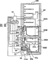
图1为示出本发明第一实施例的密闭型回转压缩机的大体构成的纵断面图。Fig. 1 is a longitudinal sectional view showing a general configuration of a hermetic rotary compressor according to a first embodiment of the present invention.
图2为图1中的A-A横断面图。Fig. 2 is a cross-sectional view of A-A in Fig. 1 .
图3为示出图1所示压缩机的压力调节装置的构造的纵断面图。FIG. 3 is a longitudinal sectional view showing the structure of the pressure regulating device of the compressor shown in FIG. 1 .
图4为示出图1所示压缩机的压力调节装置的另一例的构成的纵断面图。Fig. 4 is a longitudinal sectional view showing the configuration of another example of the pressure regulating device for the compressor shown in Fig. 1 .
图5为示出图1所示压缩机的容器内的压力和压缩室内的压力相对气缸回转角的变化所产生变化的图。FIG. 5 is a graph showing changes in the pressure in the container and the pressure in the compression chamber of the compressor shown in FIG. 1 with respect to changes in the rotation angle of the cylinder.
图6为示出本发明的第二实施例涉及的、具有将密闭容器内的压力设定得比吸入压力高而比排出压力低的压缩机的制冷循环的构成的示意图。6 is a schematic diagram showing the configuration of a refrigeration cycle including a compressor that sets the pressure in a hermetic container higher than the suction pressure and lower than the discharge pressure, according to a second embodiment of the present invention.
图7为示出使用图6的制冷循环的空调机的大体构成的图。Fig. 7 is a diagram showing a general configuration of an air conditioner using the refrigeration cycle shown in Fig. 6 .
图8为示出对本发明第三实施例的压缩机的密闭容器内的压力进行调节的构成的断面图。Fig. 8 is a cross-sectional view showing a structure for adjusting the pressure in a hermetic container of a compressor according to a third embodiment of the present invention.
图9为说明图8所示连通孔的配置位置的图。FIG. 9 is a diagram illustrating the arrangement positions of communication holes shown in FIG. 8 .
图10为说明图8所示连通孔的配置位置的图。FIG. 10 is a diagram illustrating the arrangement positions of communication holes shown in FIG. 8 .
图11为示出本发明再另一实施例的压缩机的大体构造的纵断面图。Fig. 11 is a longitudinal sectional view showing a general configuration of a compressor according to yet another embodiment of the present invention.
图12为示出本发明再另一实施例的压缩机的大体构造的纵断面图。Fig. 12 is a longitudinal sectional view showing the general structure of a compressor according to yet another embodiment of the present invention.
图13为示出图12所示压缩机的容器内的压力和压缩室内的压力相对气缸回转角的变化所产生变化的图。Fig. 13 is a graph showing changes in the pressure in the container and the pressure in the compression chamber of the compressor shown in Fig. 12 with respect to changes in the rotation angle of the cylinder.
图14为示出本发明再另一实施例的压缩机的大体构造的纵断面图、和连接了该压缩机的制冷循环的构成的示意图。Fig. 14 is a longitudinal sectional view showing the general structure of a compressor according to yet another embodiment of the present invention, and a schematic diagram showing the configuration of a refrigeration cycle to which the compressor is connected.
图15为示出使用图14的制冷循环的冰箱的大体构造的纵断面图。Fig. 15 is a longitudinal sectional view showing a general structure of a refrigerator using the refrigeration cycle of Fig. 14 .
图16为示出图14所示压缩机的容器内的压力和压缩室内的压力相对气缸回转角的变化所产生变化的图。Fig. 16 is a graph showing changes in the pressure in the container and the pressure in the compression chamber of the compressor shown in Fig. 14 with respect to changes in the rotation angle of the cylinder.
具体实施方式Detailed ways
下面,根据图1-图16说明本发明的实施例。Next, an embodiment of the present invention will be described with reference to FIGS. 1-16.
(实施例1)(Example 1)
图1示出用于制冷循环的横置型压缩机110,在其密闭容器6内具有压缩机构部和电动机部。在本实施例中,压缩机为单缸,由在缸1内回转的活塞8压缩作为制冷循环的作动流体的制冷剂。FIG. 1 shows a
该压缩机的电动机部具有由热嵌等固定于密闭容器6内的定子7和安装于驱动轴4并在定子7的内侧回转的转子5。The motor unit of this compressor has a
另外,压缩机部与上述电动机部的驱动轴4连接,由该驱动轴4的回转使配置于气缸1内的活塞(滚筒)8沿气缸内周面1a回转并往复受到驱动。在本实施例中,大体形成为圆筒形的气缸1的内侧的活塞8具有活塞8的大体圆筒形的滚筒部8a和从该滚筒部8a的圆筒面与滚筒部8a一体延伸形成的板状叶片部8b。在滚筒部8a的内周嵌入设于与驱动轴4的气缸1对应部分的偏心部4a。滚筒部8a可绕驱动轴4的偏心部4a回转地构成。The compressor unit is connected to the
如图2所示,在气缸1的圆筒状内周面1a的外侧,设置具有与该1a的中心轴大体平行的中心轴的圆筒状的孔部1b并使其一部分连通到气缸内周面1a。另外,在相对孔部1b的处于与气缸1的中心轴的相反侧(更外侧)具有同样地与孔部1b连通地设成圆筒状的孔部1c。叶片部8b插入收容到将孔部1b和孔部1c相连形成的空间。在孔部1b,夹入叶片部8b地组装可滑动地接触在叶片部8b的板状的平面部和孔部1b的内面的滑动构件9。As shown in FIG. 2, on the outside of the cylindrical inner peripheral surface 1a of the
在气缸1的两侧,与气缸1的外周构件连接地配置主轴承2和副轴承3这样的支承驱动轴的轴承构件,由轴承部2a、3a支承贯通气缸1的驱动轴4。为此,使驱动轴4的中心轴与气缸1的内周面1a的中心轴一致地设置。On both sides of the
根据以上的构成,由电动机部的转子5的回转使驱动轴4回转,从而在气缸1内对活塞8进行回转驱动,气缸内周面1a和活塞8滑动(或维持微小间隙)地回转,进行相对运动。另外,如上述那样,叶片部8b配置在与气缸1连通地设置的孔部1b和孔部1c的内部,由随着驱动轴4的回转产生的活塞8的运动进行相对偏心部4a的中心轴向的往复运动。进行该往复运动时,使滑动构件9相对叶片部8b的往复动作和回转作动与其对应地支承叶片部8b。由其运动使活塞8一边绕气缸1的内周面1a进行回转运动一边进行往复摆动。According to the above configuration, the
叶片部8b与孔部1b、1c(即作为这些叶片部8b往复、回转动作的空间的叶片室)之间的密封通过插入滑动构件9、占有孔部1b与叶片部8b之间的空间而保持。这样,由气缸1、活塞8、主轴承2、副轴承3、滑动构件9形成作为密闭空间的压缩室10与作为制冷剂的吸入空间的吸入室11,随着驱动轴4的回转反复使其容积增减。The seal between the blade portion 8b and the holes 1b, 1c (that is, the blade chamber which is the space where these blade portions 8b reciprocate and rotate) is maintained by inserting the sliding
制冷循环内部的制冷剂从贯通密闭容器6的吸入管12吸入到密闭容器6内。该吸入管12从密闭容器6外与内侧的压缩机构部连接,与容器外部的制冷剂管连接。经由吸入通道13进入到吸入室11后受到压缩。压缩后的制冷剂从形成于副轴承3的排出孔3b通过形成于该轴承的图中未示出的排出阀排出到由副轴承3和排出罩14形成的排出室3c。此后,从贯通密闭容器6的排出管15排出到密闭容器6外。The refrigerant inside the refrigeration cycle is sucked into the
这些制冷剂的吸入、排出随着活塞8的摆动而进行。即,制冷剂的吸入通过使活塞8绕驱动轴4回转(摆动)一次、增大吸入室11的容积而进行。然后,通过使活塞8绕驱动轴4回转(摆动),使得由活塞8的外周、气缸的内周面1a、主轴承2、副轴承3、及滑动构件9分隔的密闭空间的容积减少,所以,成为该空间内的制冷剂受到压缩的压缩室10。通过减少压缩室10的容积,使得室内的制冷剂受到压缩并从排出孔3b排出。The suction and discharge of these refrigerants are carried out with the swing of the
在本实施例中,使一体形成活塞8的滚筒部8a与叶片部8b的活塞8摆动。在滚筒部和叶片部分别形成的场合,需要由高压将叶片推压到滚筒部以确保压缩室的密封,所以,过去使容器内的压力更高,以高压将润滑油槽16内的润滑油供给到叶片室等。而在这样构成的本实施例中,没有这样的必要,可使压缩机的密闭容器6内为相对较低压力。In this embodiment, the
排出室3c通过改变流路断面积,作为消声器起作用,同时,还作为由流路的方向变换分离油与气体制冷剂的油分离器起作用。也可在排出室中放入金属网或钢丝棉,使得更易于捕捉油滴。分离并积存于排出室内的凹部的油通过毛细管60返回到密闭容器底部。The discharge chamber 3c functions as a muffler by changing the cross-sectional area of the flow path, and also functions as an oil separator for separating oil and gas refrigerant by changing the direction of the flow path. Metal mesh or steel wool can also be placed in the discharge chamber to make it easier to catch oil droplets. The oil separated and accumulated in the concave portion of the discharge chamber returns to the bottom of the airtight container through the capillary 60 .
下面说明本实施例的润滑油的供油的构成。Next, the structure of the lubricating oil supply of this embodiment will be described.
在本实施例中,向压缩机构和驱动轴的供油由叶片部8b的运动在润滑油施加压力而进行。如上述那样,叶片部8b的前端在孔部1c内运动,活塞8的摆动运动与叶片部8b不干涉地构成。In this embodiment, oil supply to the compression mechanism and the drive shaft is performed by applying pressure to the lubricating oil by the movement of the vane portion 8b. As mentioned above, the front-end|tip of the vane part 8b moves in the hole part 1c, and the rocking motion of the
孔部1c浸入到密闭容器6内的润滑油槽16,孔部1c位于油面下。该孔部1c的一方侧连通到吸入口17和吸入的油流往孔部1c侧的油通道。另外,另一方侧与油排出口18和排出的油通过的油通道连通。由叶片部8b的运动从吸入口17朝孔部1c的方向吸入润滑油16。另外,孔部1c内的润滑油经过油通道从排出口18挤出到供油管19的方向。此时,吸入口17和排出口18分别在从润滑油槽16到孔部1c的方向、从孔部1c到供油管19的方向减通道面积地形成,起到所谓的流体二极管的作用。The hole part 1c is immersed in the lubricating oil tank 16 in the
为此,由叶片部8b的运动使孔部1c内的润滑油不易朝润滑油槽16方向流动地形成,易于朝供油管19方向流动地形成。润滑油从供油管19流入到驱动轴4的轴端侧。然后,从形成在由副轴承3支承的驱动轴4的部分的螺旋槽20a流入到活塞滚筒部8a内的轴承部(偏心部)。然后,流入到形成于驱动轴4表面的由主轴承2支承的部分的螺旋槽20b。For this reason, the lubricating oil in the hole 1 c is formed so that it is difficult to flow toward the lubricating oil groove 16 and is formed to flow easily toward the
另外,流入到滚筒部8a内侧的润滑油对驱动轴4和滚筒部8a内的轴承部的表面进行润滑地流向电动机部侧。这样,将润滑油供给到驱动轴4和活塞8、气缸1的回转部分。然后,供给到螺旋槽20b的润滑油从主轴承2侧的螺旋槽20b的端部流出到密闭容器6内,对电动机部的转子5、定子7进行冷却,返回到润滑油16。Moreover, the lubricating oil which flowed into the inside of the roller part 8a lubricates the surface of the
另外,气缸1内的制冷剂气体有时从活塞8与气缸1的间隙流入到滚筒部8a的内侧,然后流入到活塞的滚筒部8a与偏心部4a的滑动面。此时,如在滑动面存在气体,则滚筒部8a与驱动轴4易于产生粘着,所以,需要使气体逸走。In addition, the refrigerant gas in the
在本实施例中,在驱动轴4内形成从偏心部4a连通到驱动轴4的端部的透气孔4b、4c。滑动面上的润滑油与制冷剂气体由驱动轴4的回转的离心力的作用,分离成比重相对较小的制冷剂气体和较大的润滑油,制冷剂气体流入到驱动轴4的内部侧,通过通气孔流出到密闭容器6内。In this embodiment, air holes 4 b , 4 c communicating from the eccentric portion 4 a to the end of the
另外,除了来自通气孔4b、4c的制冷剂气体外,由构成压缩室的部件间的间隙漏出的气体制冷剂使密闭容器6内的压力上升得比吸入管12内的压力高。In addition to the refrigerant gas from the vent holes 4b and 4c, the gas refrigerant leaking from the gap between the components constituting the compression chamber raises the pressure in the
下面,说明本实施例的向作动室内的供油。在本实施例中,设置了使吸入管12内的压力与密闭容器6内的压力产生规定的大小的差的装置。即,在本实施例中,设置有使由气缸内侧壁与活塞(滚筒和叶片)构成的作动室的吸入压力与容器内的空间的压力产生差别的装置。Next, the oil supply to the operating chamber of the present embodiment will be described. In this embodiment, a device is provided for causing a predetermined difference between the pressure in the
图3为本发明的使吸入管内压力与密闭容器内压力间产生差别的装置的差压阀的构造图。在该图中,阀51为闭塞设于排出罩14的开口地配置的阀。该阀51设于副轴承3内,设在与上述开口部连通的阀室50内。另外,阀51由在阀室50内的保持架54定位的螺旋弹簧52朝闭塞开口的方向施加推压力。Fig. 3 is a structural view of the differential pressure valve of the device for producing a difference between the pressure in the suction pipe and the pressure in the closed container according to the present invention. In this figure, the
另外,连通阀室50与吸入管12内地形成连通道53。阀室50使制冷剂流动方向的断面积比连通道大地设置,减小吸入管12内的制冷剂的流动速度的影响地构成。In addition, a
螺旋弹簧52产生的推压力如图所示那样为Fk+Fs(Fk:弹簧力,Fs:由阀室50内的气体加到阀51的力)的大小,如果由密闭容器6内的压力Pi作用到连通排出罩14与阀室50的通道的开口部(面积A)的力Fg不比Fk+Fs大,则阀51保持关闭状态。如Fg>Fk+Fs,则阀51被推开,连通密闭容器6内与阀室50内,因此,连通吸入管12与密闭容器6内。The pushing force generated by the
当密闭容器6内的压力超过规定的值Pi时,阀51打开,与打开压力低的吸入管12内连通,可再次使容器内的压力为Pi。这样,本实施例的压缩机在密闭容器6内的压力与吸入管12内的压力之间设定压力差,将密闭容器内的压力调节成比吸入管内的压力(吸入气体的压力)高但比排出管内的压力(排出气体压力)低的压力。When the pressure in the
图4为示出差压阀的另一构造的断面图。该图为用于形成图3所示压力的装置的变型例,图3所示例子使用螺旋弹簧52和阀51,而图4所示例子使用板簧51′。在图4的例子中,也由板簧在板簧51′施加Fk+Fs的推压力,当密闭容器6内的压力Pi产生的力Fg>Fk+Fs时,板簧被推开到阀室50侧,通过阀室50和连通道53将吸入管12内与密闭容器6内连通。Fig. 4 is a sectional view showing another configuration of the differential pressure valve. This figure shows a variant of the means for developing the pressure shown in Figure 3, the example shown in Figure 3 using a
这样,在本实施例中,密闭容器内压力由上述阀装置的作用成为比吸入管内压力高出规定值的中间的压力。Thus, in this embodiment, the pressure in the airtight container becomes an intermediate pressure higher than the pressure in the suction pipe by a predetermined value by the action of the valve device.
在上述实施例中,连接阀室50与密闭容器6内形成通道,设置调节阀室50内与容器内之间的气体流动的装置。作为这些装置,设置在阀室50内动作的阀51、51′。另外,压力的差的大小可根据例如对阀施加弹性力的螺旋弹簧52和板簧51′的强度、刚性及连通形成于排出罩14的阀室50内与密闭容器6内的空间的上述通道的面积A调节成任意的大小。另外,从容器内的空间到达吸入管的气体制冷剂流动的路径的形状,也通过在路径上设置存储气体的中间室、在流动方向上使断面积改变等适当地选择,可与装置要求的规格和压力等对应。In the above embodiments, a passage is formed between the
图5示出滚筒内侧的油通过滚筒滑动部的间隙漏入到作动室时的与其供给量相关的密闭容器压力与作动室的压力差。如关注某一瞬间吸入的气体,则回转式压缩机在曲柄一次回转进行吸入行程,在余下的一次回转进行压缩行程和排出行程。当使曲柄的回转角360°为压缩行程开始(吸入行程结束)的曲柄回转角度时,回转角0°表示吸入行程开始,回转角720°表示排出行程结束。FIG. 5 shows the pressure difference in the airtight container and the pressure difference in the operating chamber in relation to the supply amount of the oil inside the drum when it leaks into the operating chamber through the gap of the sliding part of the drum. If attention is paid to the gas inhaled at a certain moment, the rotary compressor performs the suction stroke in one revolution of the crank, and performs the compression stroke and discharge stroke in the remaining one revolution. When the rotation angle of the crank is 360° as the crank angle at which the compression stroke starts (the suction stroke ends), a rotation angle of 0° indicates the start of the suction stroke, and a rotation angle of 720° indicates the end of the discharge stroke.
实线示出吸入室和压缩室的压力,虚线示出密闭容器压力,斜线部示出其压力差。这里的条件为制冷剂R134a、吸入压力101kPa、排出压力837kPa的冰箱用压缩机的条件。在本实施例的图5(a)中,例如成为中间压力的密闭容器压力相对吸入压力形成约高出100kPa的差压地设定差压阀。成为高压密闭容器的现有例的图5(b)与图5(a)相比,显示差压的斜线部的面积较大。在高压密闭容器,过度地供给大量的油,压缩机性能(体积效率、总绝热效率)下降。在本实施例中,通过适当地设定差压,可调节成对性能有利的油量。即,在密闭容器内大体成为排压力的现有回转式压缩机中,在压缩室成为排出压力之前,从滚筒部8a向作动室内供给冷冻机油。然而,当密闭容器内成为适当的中间压力时,压缩室内的压力比中间压力高时,从滚筒部8a向压缩室的冷冻机油的供给减少,相反,冷冻机油可能向滚筒部8a移动。The solid line shows the pressure of the suction chamber and the compression chamber, the dotted line shows the pressure of the closed container, and the shaded line shows the pressure difference. The conditions here are those of a compressor for a refrigerator with refrigerant R134a, a suction pressure of 101 kPa, and a discharge pressure of 837 kPa. In FIG. 5( a ) of the present embodiment, the differential pressure valve is set such that the pressure of the airtight container, which is the intermediate pressure, is about 100 kPa higher than the suction pressure. In FIG. 5( b ), which is a conventional example of a high-pressure airtight container, the area of the shaded portion showing the differential pressure is larger than that in FIG. 5( a ). In a high-pressure airtight container, excessive supply of a large amount of oil degrades compressor performance (volume efficiency, total insulation efficiency). In this embodiment, by appropriately setting the differential pressure, the amount of oil that is beneficial to performance can be adjusted. That is, in the conventional rotary compressor in which the inside of the airtight container is substantially at the discharge pressure, the refrigerating machine oil is supplied from the roller portion 8a into the operating chamber before the compression chamber becomes at the discharge pressure. However, when the airtight container has an appropriate intermediate pressure and the pressure in the compression chamber is higher than the intermediate pressure, the supply of refrigerating machine oil from the roller portion 8a to the compression chamber decreases, and the refrigerating machine oil may migrate to the roller portion 8a conversely.
如上述那样,根据装置的规格将吸入压力与密闭容器内压力保持为设定的任意的差,减少压缩机的转速变动导致的向作动室的供油量的变化,与气体制冷剂一起从压缩室排出的油量的由压缩机转速的变化导致的变动也受到抑制。因此,应由作为油分离器起作用的排出室3c分离的油也与压缩机转速无关地在单位时间内大体为一定。As mentioned above, according to the specifications of the device, the suction pressure and the internal pressure of the airtight container are maintained at any set difference, and the change in the amount of oil supplied to the operating chamber caused by the change in the rotation speed of the compressor is reduced. Variations in the amount of oil discharged from the compression chamber due to changes in the rotational speed of the compressor are also suppressed. Therefore, the oil to be separated by the discharge chamber 3c functioning as an oil separator is substantially constant per unit time regardless of the number of rotations of the compressor.
实际的冰箱一般尽可能将箱内温度保持一定地运行,周围温度也为室温,所以,运行过程的压缩机的压力条件很少产生大的变化。因此,将由排出室3c分离了的油返回到密闭容器6底部的毛细管60两端的排出室3c内与密闭容器6内的压力差也不会产生大的变化,所以,通过适当地设定本实施例的毛细管60的节流量,可与压缩机的转速等运行条件无关地将与供给到作动室的油量大体相同的油量返回到密闭容器6的底部。因此,可减轻由于向作动室的油的供给量和向密闭容器的底部的油返回量的不平衡导致的在密闭容器的底部积存的油不足、滑动部的供油量不足导致的粘着、损伤等使得压缩机、冰箱的可靠性受到损害的程度。In actual refrigerators, the temperature inside the refrigerator is generally maintained as constant as possible, and the ambient temperature is also room temperature. Therefore, the pressure conditions of the compressor during operation rarely change greatly. Therefore, the pressure difference between the discharge chamber 3c and the
这样,通过将吸入压力和密闭容器内的压力保持为规定的值,可随着压缩机转速的变化使供给到作动室的单位时间的供油量的变动为最佳状态,另外,可使供给量减少,接近所需的最小量,所以,可抑制过去因过度供给润滑油产生的性能和可靠性的下降。In this way, by maintaining the suction pressure and the pressure in the airtight container at predetermined values, the oil supply amount per unit time supplied to the operating chamber can be optimally varied with changes in the compressor rotational speed. The supply amount is reduced to approach the minimum required amount, so the performance and reliability degradation caused by excessive supply of lubricating oil in the past can be suppressed.
另外,通过抑制向作动室供油量的变动,与气体制冷剂一起从压缩室排出的油的单位时间的变动也减小。为此,从油分离器单位时间的回油量的变动也减小,用于回油的节流的设计变得容易。In addition, by suppressing fluctuations in the amount of oil supplied to the operating chamber, fluctuations per unit time in the oil discharged from the compression chamber together with the gas refrigerant are also reduced. For this reason, fluctuations in the oil return amount per unit time from the oil separator are also reduced, and throttling design for oil return becomes easy.
另外,由于将密闭容器内压力设为在吸入压力加上规定差压后获得的压力,所以,可减小制冷剂向润滑油的溶解量,因此,对使用碳氢化合物类制冷剂的制冷循环有利。In addition, since the pressure in the airtight container is set to the pressure obtained by adding a predetermined differential pressure to the suction pressure, the amount of refrigerant dissolved in the lubricating oil can be reduced. Therefore, the refrigeration cycle using hydrocarbon refrigerants favorable.
(实施例2)(Example 2)
下面,根据图6、图7说明本发明的另一实施例。本实施例根据制冷循环的信息调节差压阀,形成对制冷循环的运行条件最佳的密闭容器内压力。压缩机的基本构造与第一实施例所示图1、图2相同,所以,相同部分采用相同符号,省略其说明。Next, another embodiment of the present invention will be described with reference to FIG. 6 and FIG. 7 . In this embodiment, the differential pressure valve is adjusted according to the information of the refrigeration cycle to form the pressure in the closed container that is optimal for the operating conditions of the refrigeration cycle. The basic structure of the compressor is the same as that shown in Fig. 1 and Fig. 2 of the first embodiment, so the same symbols are used for the same parts, and their descriptions are omitted.
在图6中,压缩机110a具有用于调节吸入管12内与密闭容器6内的压力差的压力调整阀70和压力调整管71,当压力调整阀70打开时,连通吸入管12与密闭容器6,当压力调整阀70关闭时,闭塞吸入管12和密闭容器6。In Fig. 6, the compressor 110a has a pressure regulating valve 70 and a pressure regulating pipe 71 for adjusting the pressure difference between the
包含于受到压缩的气体制冷剂的油的分离与实施例1不同,由油分离器73进行。油分离器73具有安装了流入管73a、气体流出管73b、油流出管73c的容器,使从流入管73a流入的气体制冷剂旋转到容器内,由密度差从气体分离油。气体制冷剂从气体流出管73b流出,油在容器内积存规定量时,由浮子75的作用将针阀74打开,从油流出管73c流出,通过安装于压缩机的密闭容器6的回油管72返回到密闭容器6内。The separation of the oil contained in the compressed gas refrigerant is performed by the oil separator 73 unlike the first embodiment. The oil separator 73 has a container equipped with an inflow pipe 73a, a gas outflow pipe 73b, and an oil outflow pipe 73c, rotates gas refrigerant flowing in from the inflow pipe 73a into the container, and separates oil from the gas by density difference. The gas refrigerant flows out from the gas outflow pipe 73b, and when a certain amount of oil is accumulated in the container, the needle valve 74 is opened by the action of the float 75, flows out from the oil outflow pipe 73c, and passes through the oil return pipe 72 installed in the
切换冷气和暖气运行的四通阀76、室外热交换器77、室内热交换器78、膨胀阀79、及连接配管80a、80b构成冷气和暖气运行的制冷循环地连接。风扇81、82分别为室外和室内扇。The four-way valve 76 for switching between cooling and heating operations, the outdoor heat exchanger 77, the indoor heat exchanger 78, the expansion valve 79, and the connecting pipes 80a and 80b are connected to form a refrigeration cycle for cooling and heating operations. Fans 81, 82 are outdoor and indoor fans respectively.
图7为使用图6的制冷循环的空调机的示意图。在建筑物150的内侧设置室内机112,在外侧设置室外机113。在室内机112内装室内热交换器78、风扇82等。另外,在室外机113中内装压缩机110a、室外热交换器77、风扇81等。FIG. 7 is a schematic diagram of an air conditioner using the refrigeration cycle of FIG. 6 . The indoor unit 112 is installed inside the building 150, and the outdoor unit 113 is installed outside. The indoor heat exchanger 78, the fan 82, etc. are built in the indoor unit 112. Moreover, the compressor 110a, the outdoor heat exchanger 77, the fan 81, etc. are built in the outdoor unit 113. As shown in FIG.
室温传感器120、室内热交换器温度传感器121、外气温度传感器122、室外热交换器温度传感器123、压缩机表面温度传感器124、及密闭容器内压力传感器125用于检测各部的温度和压力。另外,对室内侧控制装置130a、室外侧控制装置130b、及风扇和压缩机的转速进行控制和驱动的作为转速控制装置的变频器131、132、133进行分别对应的各部分的控制。Room temperature sensor 120, indoor heat exchanger temperature sensor 121, outside air temperature sensor 122, outdoor heat exchanger temperature sensor 123, compressor surface temperature sensor 124, and airtight container internal pressure sensor 125 are used to detect the temperature and pressure of each part. In addition, inverters 131, 132, and 133 serving as rotation speed control devices that control and drive the rotation speeds of the indoor side control device 130a, the outdoor side control device 130b, and the fan and compressor control the respective corresponding parts.
控制装置130a、130b检测来自遥控器140的设定室温、设定风量的指令,根据与室温传感器120的偏差等,向阀76、79、变频器131~133发出指令。The control devices 130a and 130b detect commands from the remote controller 140 to set the room temperature and set the air volume, and issue commands to the valves 76 and 79 and the inverters 131 to 133 based on deviations from the room temperature sensor 120 and the like.
通过将热交换器77、78中成为蒸发器的热交换器的温度传感器的温度假定为制冷剂的饱和温度,求出与其对应的饱和压力,从其减去从热交换器到压缩机吸入管的配管的压力损失,从而求出压缩机运行时的吸入压力另外,通过将热交换器77、78中成为蒸发器的热交换器的温度传感器的温度假定为制冷剂的饱和温度,求出与其对应的饱和压力,再加上从压缩机排出管到热交换器为止的配管的压力损失,从而求得排出压力。由于配管压力损失与气体密度、流速等有关,所以也可作为饱和压力、压缩机转速等的函数。这些计算由控制装置进行。By assuming the temperature of the temperature sensor of the heat exchanger serving as the evaporator among the heat exchangers 77 and 78 as the saturation temperature of the refrigerant, the corresponding saturation pressure is obtained, and subtracted from it is the temperature from the heat exchanger to the compressor suction pipe. The suction pressure when the compressor is running can be obtained by calculating the pressure loss of the pipes. In addition, by assuming the temperature of the temperature sensor of the heat exchanger that becomes the evaporator among the heat exchangers 77 and 78 as the saturation temperature of the refrigerant, the The corresponding saturation pressure is added to the pressure loss in the piping from the compressor discharge pipe to the heat exchanger to obtain the discharge pressure. Since piping pressure loss is related to gas density, flow rate, etc., it can also be used as a function of saturation pressure, compressor speed, etc. These calculations are performed by the control unit.
变频器驱动式的空调机对应于与室内外的空气温差相关的热负荷运行,所以,比起箱内温度与周围温度的变动小的冰箱的场合,压缩机的排出压力与吸入压力变化较大。因此,用于封住排出压力与吸入压力的压力差相关的作动室泄漏所需要的油量随运行条件产生较大的变动。作动室的密封保持所用的油在滚筒内侧与密闭容器内压力大体相等,所以,滚筒内侧的油在滚筒内侧与作动室的差压作用下通过滚筒滑动部的间隙漏入而进行。Inverter-driven air conditioners operate in response to heat loads related to the temperature difference between indoor and outdoor air, so the discharge pressure and suction pressure of the compressor vary greatly compared to refrigerators whose internal temperature and ambient temperature vary little. . Therefore, the amount of oil required to seal the leakage of the actuator chamber associated with the pressure difference between the discharge pressure and the suction pressure varies greatly depending on the operating conditions. The oil used for sealing and maintaining the working chamber is approximately equal to the pressure inside the drum and the airtight container, so the oil inside the drum leaks through the gap of the sliding part of the drum under the differential pressure between the inside of the drum and the working chamber.
在本实施例中,于是,通过对应于运行条件适当地调节密闭容器内压力,可进行对性能有利的量的供油。另外,预先将例如应设定的“密闭容器内压力与吸入压力的压力差”作为“排出压力与吸入压力的差”和“压缩机转速”的函数或数据存储起来,控制装置130a、130b如前面说明的那样根据热交换器温度传感器121、123的检测值等计算出的吸入压力、排出压力、及压缩机的转速向作为压缩调节装置的压力调整阀70发出指令,调节动作,使其成为所期望的密闭容器内的压力(由压力传感器125检测)。In the present embodiment, then, by appropriately adjusting the pressure inside the closed container corresponding to the operating conditions, oil supply in an amount favorable for performance can be performed. In addition, for example, the "pressure difference between the pressure in the airtight container and the suction pressure" that should be set is stored in advance as a function or data of the "difference between the discharge pressure and the suction pressure" and the "rotational speed of the compressor". As described above, the suction pressure, discharge pressure, and the rotational speed of the compressor calculated based on the detection values of the heat exchanger temperature sensors 121 and 123, etc., issue commands to the pressure regulating valve 70 as a compression regulating device, and adjust the operation so that it becomes The desired pressure inside the airtight container (detected by the pressure sensor 125).
这些存储装置安装于控制装置130a、130b内可拆下和更换,也可使用与不同条件、机种对应的存储装置和控制装置。另外,存储的数据作为各数据的组合存储,也可作为上述函数存储,使用检测出的规定的数据在控制装置内计算压力调整装置的动作量,将其作为指令发出。These storage devices are installed in the control devices 130a, 130b and can be removed and replaced, and storage devices and control devices corresponding to different conditions and models can also be used. In addition, the stored data may be stored as a combination of each data, or may be stored as the above-mentioned function, and the operation amount of the pressure regulating device may be calculated in the control device using the detected predetermined data, and issued as a command.
根据以上的构成和作用,可适当地调节随运行条件不同的向作动室的供油量地供给,减少压缩机的转速的变动导致的供油量的变动,抑制过度的供油导致的性能下降和供油量的不足导致的可靠性的下降。According to the above structure and function, it is possible to appropriately adjust the amount of oil supplied to the operating chamber depending on the operating conditions, and to reduce the fluctuation of the oil supply due to the fluctuation of the rotation speed of the compressor, and to suppress the performance caused by excessive oil supply. Decline in reliability due to drop and insufficient fuel supply.
(实施例3)(Example 3)
下面,参照图8、图9、图10、以及图1、2说明本发明的另一实施例。Next, another embodiment of the present invention will be described with reference to FIG. 8 , FIG. 9 , FIG. 10 , and FIGS. 1 and 2 .
本实施例的特征在于,在压缩机的一次回转过程中的一定区间设置连通压缩单元的压缩室与密闭容器内的孔,代替第一实施例的图3、图4所示的差压阀。压缩机的基本构造与第一实施例所示图1、图2相同,省略其说明。The feature of this embodiment is that a hole connecting the compression chamber of the compression unit and the airtight container is provided at a certain interval during one revolution of the compressor, instead of the differential pressure valve shown in Fig. 3 and Fig. 4 of the first embodiment. The basic structure of the compressor is the same as that shown in Fig. 1 and Fig. 2 of the first embodiment, and its description is omitted.
在日本特开昭55-107093号公报中公开了一种这样的例子,该例子在涡卷压缩机中通过设置使压缩机部与密闭容器内连通的开孔,将密闭容器内形成为吸入压力与排出压力的中间压力,与本实施例的回转式压缩机的目的和作用不同。在上述公报的涡卷压缩机中,通过使密闭容器内压力为中间压力,作用与作用于旋转涡卷构件的轴向力相反方向的推压力。另外,在上述公报的涡卷压缩机中,由毛细管连接密闭容器的底部与吸入管,由密闭容器内压力(中间压力)与吸入压力的差压从吸入管向压缩机部供油。另一方面,在本实施例的回转式压缩机中,通过滚筒滑动部间隙向作动室供油。An example of this is disclosed in Japanese Patent Application Laid-Open No. 55-107093. In this example, an opening for communicating the compressor part with the inside of the airtight container is provided in the scroll compressor to form a suction pressure in the airtight container. The intermediate pressure from the discharge pressure is different from the purpose and function of the rotary compressor of this embodiment. In the scroll compressor disclosed in the above-mentioned publication, by making the internal pressure of the airtight container an intermediate pressure, a pressing force acting in a direction opposite to the axial force acting on the orbiting scroll member acts. In addition, in the scroll compressor of the above-mentioned publication, the bottom of the airtight container and the suction pipe are connected by a capillary tube, and oil is supplied from the suction pipe to the compressor part by the difference between the internal pressure (intermediate pressure) of the airtight container and the suction pressure. On the other hand, in the rotary compressor of this embodiment, the oil is supplied to the operation chamber through the gap of the roller sliding portion.
在图8中,孔100开设于压缩单元的主轴承侧的端板,为与密闭容器内空间连通的孔。孔100按回转角540°(180°)和其近旁的回转角与压缩室连通,在其它区间,由滚筒端面闭塞。该孔100与制冷剂气体的排出孔分别设置,可仅在压缩工序的任意的时刻、时间连通缸内的作动室内与密闭容器内的空间。In FIG. 8 , a
压缩室压力Pc为吸入压力Ps的(Vc/Vs)k倍(Vs:排除容积,Vs:压缩室容积,k:绝热指数),例如在R134a的场合,如冰箱的压缩机吸入压力为101kPa,则回转角540°的压缩室压力约为230kPa(参照图5)。因此,仅在回转角540°和其近旁的回转角连通压缩室内与密闭容器内的空间,从而在在回转角540°和其近旁的回转角的压缩室压力与密闭容器内压力产生差压时,气体通过连通孔100来到,在稳定状态下,可将密闭容器内压力保持在比吸入压力约高130kPa的压力。这样,与实施例1同样,可由差压向作动室供油。The compression chamber pressure Pc is (Vc/Vs)k times the suction pressure Ps (Vs: excluded volume, Vs: compression chamber volume, k: adiabatic index), for example, in the case of R134a, the suction pressure of the refrigerator compressor is 101kPa, Then the pressure in the compression chamber with a rotation angle of 540° is about 230kPa (refer to FIG. 5 ). Therefore, only at the turning angle of 540° and its vicinity, the space in the compression chamber and the airtight container is communicated, so that when the pressure in the compression chamber at the turning angle of 540° and its vicinity is differential pressure and the pressure in the airtight container , the gas comes through the
下面,参照图9、图10说明连通孔100的配置位置。在这里,说明在回转角495°~585°的范围连通压缩室与密闭容器内空间的场合。图9(a)的斜线部示出由在回转角0°~360°的范围形成的吸入室(吸入工序)的区域及在回转角360°~495°的范围形成的压缩室(压缩、排出工序)的区域。该区域包括由气缸内周、以(活塞滚筒部外半径-偏心量)作为半径的圆(由虚线示出的圆周部分)、回转角495°处的活塞滚筒部外周、及活塞的其它轨迹围住的区域构成。图9(b)的斜线部示出在回转角495°~585°的范围形成的压缩室的区域。该区域包括由缸内周、回转角495°处的活塞滚筒部外周、以(活塞滚筒部外半径-偏心量)为半径的圆(以虚线示出的圆周部分)、及叶片部等围住的区域。另外,图9(c)的斜线部示出在回转角585°~720°(0°)的范围形成的压缩室的区域。该区域包括由气缸内周、回转角585°处的活塞滚筒部外周、及叶片部等围住的区域。Next, arrangement positions of the communication holes 100 will be described with reference to FIGS. 9 and 10 . Here, the case where the compression chamber communicates with the inner space of the airtight container in the range of the rotation angle of 495° to 585° will be described. The hatched part of Fig. 9 (a) shows the area of the suction chamber (suction process) formed in the range of the rotation angle of 0° to 360° and the compression chamber (compression, compression) formed in the range of the rotation angle of 360° to 495°. discharge process) area. This area includes the inner circumference of the cylinder, the circle with the radius of (piston roller part outer radius - eccentricity) (circumference part shown by the dotted line), the outer circumference of the piston roller part at the rotation angle of 495°, and other trajectory circumferences of the piston. Composition of living area. The hatched portion in FIG. 9( b ) shows the region of the compression chamber formed in the range of the swivel angle of 495° to 585°. This area is surrounded by the inner circumference of the cylinder, the outer circumference of the piston roller at a rotation angle of 495°, a circle with a radius of (outer radius of the piston roller - eccentricity) (circumferential part shown by a dotted line), and blades, etc. Area. In addition, the hatched portion in FIG. 9( c ) shows the region of the compression chamber formed in the range of the swivel angle of 585° to 720° (0°). This area includes the area surrounded by the inner circumference of the cylinder, the outer circumference of the cylinder portion of the piston at a rotation angle of 585°, the blade portion, and the like.
为了仅在回转角495°~585°的区间连通压缩室与密闭容器内空间,可在图9(b)的斜线部中的不与(a)和(c)的斜线部相交的部分的主轴承侧端板部设置连通孔。该区域在图10中由斜线示出。In order to connect the compression chamber and the inner space of the airtight container only in the interval of the rotation angle of 495°~585°, it can be used in the part of the oblique line in Fig. 9(b) that does not intersect with the oblique line of (a) and (c). The end plate on the main bearing side is provided with a communicating hole. This region is indicated by oblique lines in FIG. 10 .
该区域包括由以(活塞滚筒部外部半径-偏心量)为半径的圆(由虚线示出的圆周部分)、回转角495°~540°的滚筒·叶片连接部的轨迹、回转角495°处的活塞滚筒部外周等围住的区域。相当于以(活塞滚筒部外半径-偏心量)为半径的圆的内侧相当的主轴承端板部不时常与压缩室连通,所以,也可在包含该部分的斜线部如图所示那样设置连通孔100。另外,孔100的形状与图3、4同样地对应于求出的规格和压力的大小任意地具有长度和断面积等形状。This area includes a circle with a radius of (piston roller part outer radius - eccentricity) (circumferential part shown by a dotted line), the trajectory of the roller-vane connection part with a rotation angle of 495° to 540°, and the position at the rotation angle of 495° The area surrounded by the outer circumference of the piston cylinder. The end plate portion of the main bearing corresponding to the inner side of the circle with the radius of (piston cylinder portion outer radius - eccentricity) does not always communicate with the compression chamber, so the hatched portion including this portion can also be used as shown in the figure. Communication holes 100 are provided. In addition, the shape of the
在本实施例中,在压力上升的压缩工序,通过将仅在规定时间、回转角之间连通压缩室与容器内的通道的开口设置到气缸的内侧壁面上,可使容器内压力比吸入压力高任意的大小,或设定得比排出压力低。由同样的构成,在从制冷剂的吸入到压缩、排出的工序的活塞滚筒的任意的位置、间隔,连通作动室内与密闭容器内的空间,使制冷剂气体流通,从而可将密闭容器内设定为从吸入到排出的任意的压力。这样,根据吸入压力、排出压力产生的所期望的压力差,可适当地调节向作动室内供给润滑油的量。In this embodiment, in the compression process of pressure increase, the opening of the passage connecting the compression chamber and the container is provided on the inner wall surface of the cylinder only during the predetermined time and the rotation angle, so that the pressure in the container can be made higher than the suction pressure. High arbitrary size, or set lower than the discharge pressure. With the same structure, at any position and interval of the piston roller in the process from the suction of the refrigerant to the compression and discharge, the space in the operating chamber and the airtight container is communicated, and the refrigerant gas is circulated, so that the airtight container can be closed. Set to any pressure from suction to discharge. In this way, the amount of lubricating oil supplied to the operating chamber can be appropriately adjusted according to the desired pressure difference between the suction pressure and the discharge pressure.
在本实施例中,作为将压缩机的密闭容器内压力保持为中间压力的机构,在主轴承端板设置连通孔,所以,与实施例1的差压阀相比,可实现低成本化。In this embodiment, communication holes are provided in the main bearing end plate as means for maintaining the pressure in the airtight container of the compressor at an intermediate pressure, so that the cost can be reduced compared with the differential pressure valve of the first embodiment.
(实施例4)(Example 4)
下面,参照图11说明本发明的另一实施例。Next, another embodiment of the present invention will be described with reference to FIG. 11. FIG.
图11为本发明第四实施例的压缩机的纵断面图,压缩机为滚动活塞型双缸回转式压缩机。在直到实施例3的实施例中,使用滚动活塞的压缩机为滚筒部与叶片部成一体的构成,这些实施例与本实施例的不同点在于,气缸内的活塞由滚筒部与叶片部由分开的部件构成。Fig. 11 is a longitudinal sectional view of a compressor according to a fourth embodiment of the present invention, and the compressor is a rolling piston type double-cylinder rotary compressor. In the embodiments up to
图11示出用于制冷循环的横置式压缩机110b,在该密闭容器6内具有压缩机构部和电动机部。在本实施例中,压缩机为双缸,由在气缸22a、22b内回转的滚筒活塞27a、b对制冷循环的制冷剂进行压缩。压缩机构部与电动机部的驱动轴4连接,由该驱动轴4的回转使配置于缸内的活塞(滚筒)27a、b沿内周面22c、d回转,受到往复驱动,这一点与上述实施例相同。FIG. 11 shows a horizontal compressor 110b used in a refrigeration cycle, and has a compression mechanism unit and a motor unit in the
另外,在本实施例中,也将滚筒活塞27a、b的内周侧嵌入到设在驱动轴4上的与气缸对应的部分的偏心部26a、b。滚筒活塞27a、b可绕驱动轴4的偏心部4a回转地构成。Also in this embodiment, the inner peripheral sides of the roller pistons 27a, b are fitted into the eccentric portions 26a, b provided on the
如图11所示,叶片部28a、b收容组装到在气缸22a、b外侧与其连通地设置的叶片室,从与滚筒活塞27a、b相反侧由各弹簧29a、b施加弹性力,推压到滚筒。另外,与上述实施例同样,在气缸的两侧与气缸的外周构件连接地配置主轴承24和副轴承25这样的支承驱动轴的轴承构件,由轴承部24a、25a支承贯通气缸22a、b内的驱动轴26。为此,使驱动轴26的中心轴与气缸22a、b的圆筒状的内周面22c、d的中心轴一致地设置,随着驱动轴4的回转,使在气缸1内受到回转驱动的滚筒活塞27a、b与内周面滑动(或维持微小间隙)地回转,进行相对运动,同时,叶片部28a、b在维持朝与气缸连通地设置的滚筒的径向(驱动轴26方向)被推压到滚筒的状态进行往复运动。当进行该往复运动时,叶片在被推压到滚筒的接触面上相对滚筒的径向移动进行滑动。这样,由这些构成形成作为密闭空间的压缩室与制冷剂的吸入空间的吸入室,随着驱动轴的回转,使其容积反复增减。As shown in FIG. 11, the vane parts 28a, b are accommodated and assembled in the vane chambers provided outside the cylinders 22a, b in communication with them, and elastic forces are applied from the opposite side to the roller pistons 27a, b by springs 29a, b, and pushed to roller. In addition, similarly to the above-mentioned embodiment, the bearing members supporting the drive shaft such as the
在本实施例的构成中,在具有压缩气的制冷循环中进行循环的制冷剂从贯通密闭容器6的吸入管12吸入到密闭容器6内,经由吸入通道进入到气缸22a、22b的吸入室后受到压缩。压缩后的制冷剂从形成于副轴承25的排出孔30a、b通过形成于该轴承的排出阀排出到由副轴承25和排出罩31a、b形成的排出室32a、b。排出到排出室32a的制冷剂通过连通排出室32a、b的通道流出到排出室32b,之后,从贯通密闭容器6的排出管15排出到密闭容器6外。在排出室32b的排出管15的下方设置包含于排出制冷剂气体中的润滑油积存的空间,积存的该空间的润滑油通过与设于排出室32b下部的开口连通的毛细管60流出到润滑油槽16。In the configuration of this embodiment, the refrigerant circulating in the refrigeration cycle with compressed gas is sucked into the
本实施例的润滑油的供油的构成也与上述实施例同样地进行,由叶片部28a、b的往复动作对从油吸入口33吸入到叶片室内的润滑油施加压力,通过通道19供给到驱动轴26的前端。此时,吸入口33朝从孔部1c到供油管19的方向减少通道面积地形成,起到所谓的流体二极管的作用。另外,由形成于驱动轴26的部分的螺旋槽20向活塞滚筒部内的轴承部(偏心部)和主、副轴承24、25的轴承部供给润滑油,同时,由设于轴内的通道使产生于偏心部的轴承部的气体朝电动机部侧流出,这一点也与上述实施例相同。The oil supply structure of the lubricating oil in this embodiment is also performed in the same manner as in the above-mentioned embodiment. The lubricating oil sucked into the vane chamber from the
另外,除了来自上述通气孔的制冷剂气体外,还由通过构成压缩室的部件间的间隙漏出的气体制冷剂使密闭容器6内的压力上升得比吸入管12内的压力高。本实施例也设置有使吸入管12内的压力与密闭容器6内的压力产生规定大小的差的装置。通过设置在上述实施例中说明的用于任意产生吸入管38内的压力(吸入室内压力)与密闭容器6内压力的差的装置的作用效果在本实施例中也可同样获得。In addition, the pressure in the
在本实施例中,如现有技术那样,使容器内压力比使密闭容器6内的压力与排出管内的压力相同的场合低地设定。所以,过去由于对润滑油施加了相对较高的压力、送到叶片室,将叶片推压到滚筒,所以,为了抑制在滚筒与叶片部间产生局部较大的面压而产生粘着、磨损、损伤,需要向作动室供给大量的润滑油,而在本实施例中,由于将叶片推压到滚筒的力相对较低,所以,供给的润滑油的量也可减少。In the present embodiment, the pressure in the container is set lower than that in the case where the pressure in the
作动室的密封和滚筒/叶片润滑所需要的润滑油的供给量如上述那样,例如可根据对阀施加弹性力的弹簧的强度和连通道的面积、形状等适当地调节。另外,容器内的压力由于可比现有技术的压缩机的场合低,所以,在使用碳氢化合物类制冷剂的场合也可减少溶入量,减少制冷剂量,所以,可提高制冷循环和具有其的冷冻、空调装置的安全性和可靠性。The supply amount of lubricating oil required for sealing the working chamber and lubricating the roller/vane can be appropriately adjusted according to, for example, the strength of the spring that applies elastic force to the valve, the area and shape of the communication passage, as described above. In addition, since the pressure in the container can be lower than that of the compressor of the prior art, it is also possible to reduce the dissolved amount and reduce the amount of refrigerant when using hydrocarbon refrigerants, so that the refrigeration cycle and other functions can be improved. The safety and reliability of refrigeration and air conditioning equipment.
(实施例5)(Example 5)
下面,参照图12~13说明本发明的再另一实施例。Next, still another embodiment of the present invention will be described with reference to FIGS. 12 to 13 .
图12的压缩机为具有使用了摆动活塞的二个压缩单元的压缩机,涉及将在一方的压缩单元受到了压缩的制冷剂供给到另一方的压缩单元再次进行压缩的所谓的二级压缩机。图13为示出随着活塞的回转位置变化的密闭容器内的空间与作动室内的压力的差的图。作为调节密闭容器内的压力的装置,可使用图3、图4的阀装置、图8的连通孔等。The compressor shown in FIG. 12 is a compressor having two compression units using swing pistons, and relates to a so-called two-stage compressor that supplies refrigerant compressed in one compression unit to the other compression unit and compresses it again. . Fig. 13 is a graph showing the difference in pressure between the space in the airtight container and the operating chamber as the rotational position of the piston changes. As means for adjusting the pressure in the airtight container, the valve device shown in FIG. 3 and FIG. 4 , the communication hole shown in FIG. 8 , and the like can be used.
本实施例的压缩机110c大体具有低压(低级吸入压力)、比低压高的中间压(低级排出压力、高级吸入压力)、比中间压高的高压(高级排出压力)的三个压力级。在本实施例中,压缩机密闭容器内压力不是采用该三个压力中的一个,而是可对性能有利地任意地设定密闭容器内的压力。The compressor 110c of this embodiment generally has three pressure stages: low pressure (lower suction pressure), intermediate pressure higher than the low pressure (lower discharge pressure, higher suction pressure), and higher pressure than the intermediate pressure (higher discharge pressure). In this embodiment, the pressure in the airtight container of the compressor is not one of the three pressures, but the pressure in the airtight container can be arbitrarily set to benefit the performance.
在图12中,制冷循环内的气体制冷剂从贯通密闭容器6的第一吸入管36吸入到密闭容器6内,在构成第一压缩单元的第一气缸1′内进行第一次压缩。压缩后的气体制冷剂从排出孔30b通过排出室32b流出到第一排出管37。即,由第一压缩单元进行第一级压缩。制冷剂在此后从贯通密闭容器6的第一排出阀37排出到密闭容器6外。In Fig. 12, the gas refrigerant in the refrigeration cycle is sucked into the
一时排出到密闭容器6外的气体制冷剂通过中间冷却器38由周围空气冷却,然后由贯通密闭容器6的第二吸入管39再次吸入到密闭容器6内。吸入到吸入管39的气体制冷剂在构成第二级压缩单元的第二气缸1″内部进行第二次压缩,从排出孔30a通过排出室32a流出到第二排出管40。即,进行第二级压缩。制冷剂此后从排出管40排出到密闭容器6外。The gas refrigerant discharged out of the
此时,密闭容器内压力由在实施例1、2中详细说明的设定密闭容器内压力的装置保持为比第一气缸1′的吸入压力高但比制冷剂的排出压力低的压力。在图3、图4所示阀装置的场合,通过阀连接第一吸入管36内与密闭容器6内。另外,在图8所示连通孔的场合,连通由第一气缸1′等形成的低级侧(第一级)的压缩单元的作动室与密闭容器内的规定区间地设置。At this time, the pressure in the airtight container is maintained at a pressure higher than the suction pressure of the first cylinder 1' but lower than the discharge pressure of the refrigerant by the device for setting the pressure in the airtight container detailed in
在本实施例中,为了实现高性能化,使低级侧与高级侧的压缩功相等地设定低级压缩单元和高级压缩单元的排气量,并使得在规定压力条件下低级侧的压缩比与高级侧的压缩比大体相同。In this embodiment, in order to achieve high performance, the compression work of the low-stage side and the high-stage side are set equal to the displacement of the low-stage compression unit and the high-stage compression unit, and the compression ratio of the low-stage side is equal to the Compression ratios are about the same on the advanced side.
图13示出作动室内压力和密闭容器内压力随二级压缩机的第一级(低级)的压缩单元和第二级(高级)的压缩单元的曲柄回转角的变化。实线示出吸入室和压缩室的压力,虚线示出密闭容器压力,斜线示出其压力差。其条件为制冷剂134a、低级侧吸入压力101kPa、高级侧排出压力837kPa的冰箱用压缩机的条件。此时,低级侧与高级侧的压力比大体相同,低级侧排出压力和高级侧吸入压力为291kPa。FIG. 13 shows the variation of the pressure in the working chamber and the pressure in the airtight container with the crank angles of the first stage (lower stage) compression unit and the second stage (higher stage) compression unit of the two-stage compressor. The solid line shows the pressure of the suction chamber and the compression chamber, the dotted line shows the pressure of the closed container, and the oblique line shows the pressure difference. The conditions are those of a compressor for a refrigerator with refrigerant 134a, a low-stage suction pressure of 101 kPa, and a high-stage discharge pressure of 837 kPa. At this time, the pressure ratios of the low-stage side and the high-stage side are substantially the same, and the discharge pressure of the low-stage side and the suction pressure of the high-stage side are 291 kPa.
如现有技术那样,作为图13(b)所示的密闭容器的压力,在使用高级吸入压力的场合,对于低级压缩单元,高级吸入压力291kPa与作动室(吸入室、压缩室)压力的压力差(斜线部)成为驱动力,滚筒内侧的油通过滚筒滑动部的间隙供给到第一气缸1′,进行该作动室的密封。对于高级压缩单元的作动室密封用的油,从低级压缩单元与气体制冷剂一起排出的油通过高级压缩单元的吸入管供给到作动室。As in the prior art, as the pressure of the airtight container shown in Fig. 13(b), when the high-level suction pressure is used, for the low-level compression unit, the difference between the high-level suction pressure 291kPa and the pressure of the operating chamber (suction chamber, compression chamber) The pressure difference (hatched portion) becomes the driving force, and the oil inside the drum is supplied to the first air cylinder 1' through the gap of the sliding portion of the drum to seal the working chamber. As for the oil for sealing the working chamber of the high-stage compression unit, the oil discharged from the low-stage compression unit together with the gas refrigerant is supplied to the working chamber through the suction pipe of the high-stage compression unit.
此时,在图13(b),供给超出最小极限所需要的过度的油,由大量的高温的油加热制冷剂,在压缩机的体积效率、总绝热效率下降的场合,在本实施例中,如图13(a)所示那样,通过将密闭容器内压力设定为比高级吸入压力低的值,可使供油量最佳化,提高性能。在该场合,即使压缩机的转速增减,也可减小供给到第一气缸1′内的润滑油的量的变动,抑制过度供给润滑油导致的压缩机的效率下降,提高性能。另外,流入第二气缸的润滑油由供给到第一气缸并包含于制冷剂气体中流通的润滑油进行。对应供到该第二气缸的量也加以考虑,可调节设定通往第一气缸1′的吸入管36内的压力与密闭容器6内的压力的差。At this time, in Fig. 13(b), the excess oil required beyond the minimum limit is supplied, and the refrigerant is heated by a large amount of high-temperature oil, and when the volumetric efficiency and total insulation efficiency of the compressor decrease, in this embodiment , as shown in Figure 13(a), by setting the pressure in the airtight container to a value lower than the high-level suction pressure, the oil supply amount can be optimized and the performance can be improved. In this case, even if the rotational speed of the compressor increases or decreases, fluctuations in the amount of lubricating oil supplied to the first cylinder 1' can be reduced, thereby suppressing reduction in efficiency of the compressor due to oversupply of lubricating oil, and improving performance. In addition, the lubricating oil flowing into the second cylinder is performed by the lubricating oil supplied to the first cylinder and circulated in the refrigerant gas. The difference between the pressure in the suction pipe 36 leading to the first cylinder 1' and the pressure in the
相反,在图13(b)的场合,当向作动室的供油不足时,可将密闭容器内压力设定得比高级吸入压力高。Conversely, in the case of FIG. 13(b), when the oil supply to the actuating chamber is insufficient, the pressure in the airtight container can be set higher than the high-stage suction pressure.
(实施例6)(Example 6)
下面,参照图14~15说明本发明的再另一实施例。Next, still another embodiment of the present invention will be described with reference to FIGS. 14 to 15 .
图14所示压缩机为使用上述摆动活塞的回转式压缩机。但是,在本实施例中,在循环的途中具有阀的切换装置,可切换由一个压缩室进行的压缩和由二个压缩室进行的压缩。本实施例的压缩机也具有调节密闭容器内的装置,具有在作动室的吸入管内的压力与容器内的空间的压力之间产生任意的值的压力差的构成。作为该压力的调节装置,也可使用上述实施例中说明的任何装置。The compressor shown in Fig. 14 is a rotary compressor using the swing piston described above. However, in this embodiment, there is a valve switching device in the middle of the cycle, and it is possible to switch between compression performed by one compression chamber and compression performed by two compression chambers. The compressor of this embodiment also has a device for regulating the inside of the airtight container, and has a configuration to generate a pressure difference of an arbitrary value between the pressure in the suction pipe of the operating chamber and the pressure in the space in the container. As the means for adjusting the pressure, any of the means described in the above-mentioned embodiments can also be used.
在图14中,本实施例的制冷循环的大体构成包括具有二个气缸的压缩机110d、冷凝器62、冷冻室用蒸发器64a、冷藏室用蒸发器64b、及将其连接并使制冷剂在其内部流通的制冷剂管。另外,在冷凝器62和蒸发器64分别配置用于送风的送风扇66、67、68。这样,在本实施例中,由压缩机110d压缩后的制冷剂从排出管40流出,送到冷凝器62,之后,分流到冷冻室用蒸发器64a和冷藏室用蒸发器64b。从这些蒸发器流出的制冷剂通过制冷剂管再次流入到压缩机进行压缩,构成循环。In Fig. 14, the general structure of the refrigeration cycle of this embodiment includes a
本实施例的压缩机110d具有二个气缸1′、1″,它们分别具有用于吸入和排出制冷剂气体的吸入管36、39和37、40。由这些气缸可将由第一气缸1′压缩后的制冷剂气体送到第二气缸1″再次进行压缩,即所谓的二级压缩。The
为此,由与第一气缸1′的排出管37连接的制冷剂管形成的制冷剂的流动分成二个方向,一方通过连接第二气缸的排出管40和冷凝器62的制冷剂路径和单向阀61b由制冷剂管连接,另一方在连接冷冻室用的冷藏室用蒸发器64b和第二气缸1″的吸入管39的制冷剂路径通过中间冷却器38由制冷剂管连接。另外,在该分支部与中间冷却器38之间配置对制冷剂的流动进行调节的电磁阀65b。For this reason, the flow of refrigerant formed by the refrigerant pipe connected to the
另外,与冷凝器62连接、来自冷凝器的制冷剂流动的制冷剂管分支成二个管,分别通过毛细管63a、b将一方连接到冷冻室用的蒸发器64a,将另一方连接到冷藏室用蒸发器64b。即,冷冻室用毛细管63a、冷藏室用毛细管63b配置到制冷剂管的分支部与各蒸发器之间,与从蒸发器流出的制冷剂流动的制冷剂管进行热交换地例如相互接触地设置。另外,在上述分支部与冷藏室用毛细管63b之间设置可调节制冷剂流动的电磁阀65a。In addition, the refrigerant pipe connected to the
另外,使得从冷冻室用蒸发器64a流出的制冷剂流入到第一气缸1′的吸入管36地由制冷剂管设置制冷剂路径,同时,在从冷藏室用蒸发器64b流出的制冷剂流入到第二气缸的吸入管39的制冷剂路径通过单向阀61a流入地分支设置制冷剂管。In addition, a refrigerant path is provided by the refrigerant pipe so that the refrigerant flowing out of the
在这样的构成中,由单向阀61a、b、电磁阀65a、b的动作调节制冷剂的流动,可将使用压缩机的第一、第二气缸1′、1″的制冷剂的压缩在上述二级压缩动作与在二个气缸并列地对制冷剂进行压缩的并列压缩间进行切换。即,可切换成这样的制冷剂的流动路径,在该制冷剂的流动路径中,从冷凝器62分支流动,在冷冻室用蒸发器64a进行了蒸发的制冷剂流入到吸入管36,同时,由冷藏室用蒸发器65a蒸发了的制冷剂在第一气缸受到压缩,与从排出管37流出的制冷剂汇合后流入到第二气缸的吸入管39,压缩后,从排出管40流出;另外,也可切换成这样的制冷剂的流动路径,在该制冷剂的流动路径中,从冷凝器62流出、在冷冻室用蒸发器64a进行了蒸发的制冷剂分别分支流入到第一、第二气缸的吸入管36、39,经压缩后,从排出管37、40流出。In such a structure, the flow of the refrigerant is regulated by the actions of the check valves 61a, b and the
在图15中,本实施例的冰箱具有图14所示的制冷循环,具有与其相适合的构成。冰箱本体200在其内部设置多个储藏室,从上开始具有冷藏室203A、蔬菜室203B、上下二级的冷冻室202A、202B。在冰箱200内设置多个蒸发器,在上级冷冻室202A后部配置冷冻室用蒸发器64a,在蔬菜室203B后部配置冷藏室用蒸发器64b,在这些蒸发器的上方配置用于向蒸发器供给空气流的风扇67、68。In FIG. 15, the refrigerator of this embodiment has the refrigerating cycle shown in FIG. 14, and has a configuration suitable therefor. Refrigerator
通过风扇的回转而在这些蒸发器冷却了的空气具有由不同的路径供给到储藏室、从储藏室流出后返回到蒸发器的循环路径。即,具有由冷冻室用蒸发器64a冷却、通过风扇67流出到冷冻室202A、B内后成为从下级冷冻室202B后部返回到蒸发器64a的冷气流的循环路径和由蒸发器64b冷却、通过风扇68供给到冷藏室203A、冷却了冷藏室203A后流入到蔬菜室203B、成为从蔬菜室内的容器后方返回到蒸发器64b的冷气流的循环路径。为了分离这些冷气流,在冷冻室202A与蔬菜室203B之间配置具有绝热材料的分隔壁。The air cooled by these evaporators by the rotation of the fans has a circulation path that is supplied to the storage compartment through different paths, flows out of the storage compartment, and then returns to the evaporator. That is, there is a circulation path of cooling by the
另外,在冰箱200的背面侧的底部的冷冻室的后方配置压缩机110d、冷凝器62、冷凝器用风扇66、及电磁阀65a、b。另外,本实施例的冰箱具有用于调节图14所示制冷循环的动作的控制装置231。该控制装置接受检测冷冻室内的温度的温度传感器218、检测冷冻室和蔬菜室的温度的温度传感器219、及检测蒸发器的温度的温度传感器220、221的输出,向可变地调节压缩机110d的电动机、冷凝器用风扇66、蒸发器用风扇67、68的转速的变频器232、233、234、235发出指令,调节箱内的制冷能力。另外,向电磁阀65a、b发出对其动作进行调节的指令,切换制冷剂的流动,切换压缩机110d的二级压缩、并列压缩的运行。另外,指令各蒸发器用的除霜加热器216、217的运行,加热蒸发器进行除霜。Also,
在本实施例中,在冷藏室203A的门上可由使用者任意地调节冰箱200的运行地设置操作板236,可由该板236的操作向控制装置231发出运行指令。另外,与冰箱200的各储藏室内的冷却运行和切换的制冷剂的流动、压缩机110d的运行对应,由电磁阀65a、65b的动作进行。In this embodiment, an
例如,冷冻室、冷藏室内的温度都比预先设定的开始冷却运行时的温度高的场合,由控制装置231判断需要冷却双方的储藏室,使电磁阀65a、b一起动作到打开位置地指令。在该场合,来自冷凝器62的制冷剂分支,分别流入到冷冻室用蒸发器64a、冷藏室用蒸发器64b,对冷冻室和冷藏室进行冷却。来自冷冻室用蒸发器64a的制冷剂从吸入管36流入到第一气缸1′,受到压缩后从排出管37排出。For example, when the temperatures in both the freezer compartment and the refrigerator compartment are higher than the preset temperature at the start of the cooling operation, the
来自冷藏室用蒸发器64b的制冷剂与来自排出管37的制冷剂汇合后,从吸入管39流入到第二气缸1″受到压缩。即,通过冷冻室用蒸发器64a的制冷剂由第一气缸1′和第二气缸1″进行多次压缩。The refrigerant from the refrigerating
在仅冷冻室比预先设定的冷却开始温度高的场合,或根据来自操作板236的指令强制地指令冷冻室的冷却运行的场合,进行单独地仅冷却冷冻室的运行。在该场合,电磁阀65a关闭,进行电磁阀65b的打开动作地从控制装置发出指令。这样,来自冷凝器62的制冷剂仅流入冷冻室用蒸发器64a,从蒸发器64a流出的制冷剂分支到第一、第二气缸1′、1″,从吸入管36、39流入,并列地压缩。即,来自冷冻室用蒸发器64a的制冷剂由各气缸并列地压缩,分别排出,汇合后流入到冷凝器62,这样,进行并列地压缩的运行。When only the freezer compartment is higher than the preset cooling start temperature, or when the cooling operation of the freezer compartment is forcibly instructed by an instruction from the
在本实施例中,密闭容器6内的压力也由在第一、第二实施例中详细说明的设定密闭容器内的压力的装置调节成比第一气缸的吸入管内的压力高、比排出管内的压力低的压力。排出管内的压力可为第一气缸的场合,也可为第二气缸的场合,在第二气缸的场合,与冷凝器入口的制冷剂的饱和压力大体相等。本实施例具有将密闭容器内的压力设定为这些压力的中间值的装置。In this embodiment, the pressure in the
在图3、图4所示的差压阀的场合,第一吸入管36内与密闭容器6内通过差压阀连接。另外,在图8所示连通孔的场合,在规定区间连接由第一气缸1′等形成的压缩室与密闭容器内地设置。这样,密闭容器6内的压力与上述二级的压缩和并列压缩时一起保持为比吸入管36的吸入压力高规定的压力。In the case of the differential pressure valve shown in FIGS. 3 and 4 , the inside of the first suction pipe 36 is connected to the inside of the
在二级压缩的场合,对于由第一气缸1′侧的排出室32b分离的油,由于设在配置于排出室32b的排出管37的开口下方并且与设于排出室32b内的开口连通的毛细管60a的两端的压力差即排出室32b内与密闭容器6内的压力差较小,所以,不容易返回到密闭容器6内,存储于排出室32b内,当过度积存时,随着制冷剂气体一起通过第一排出管37流出。In the case of two-stage compression, the oil separated from the discharge chamber 32b on the side of the first cylinder 1' is located below the opening of the
从低级的压缩单元(来自冷冻室用蒸发器64a的制冷剂受到第一级压缩)第一气缸1′侧流出的油与气体制冷剂一起供给到高级压缩单元(对于来自冷冻室用蒸发器64a的制冷剂进行第二级压缩的第二气缸1″),进行作动室的密封作用。从该高级压缩单元排出的油在排出室32a内与存储于容器下方与制冷剂气体分离,由更高压力的高级的排出压力与密闭容器6内的压力的差压通过毛细管60b返回到密闭容器6内底部。The oil flowing out of the first cylinder 1' side from the low-stage compression unit (refrigerant from the
对于在并列地进行单级压缩的场合的油的分离,由各排出室32a、32b分离的油由排出压力与密闭容器内的压力的差压通过毛细管60a、60b返回到密闭容器6内的底部。For the separation of oil in the case of performing single-stage compression in parallel, the oil separated by each discharge chamber 32a, 32b is returned to the bottom of the
此时,在二级压缩和并列的压缩双方的场合,由排出室32a分离了的油通过毛细管60b返回到密闭容器6内。与二级压缩时的排出室32a的回油量相关的向作动室的供油量与图16(a)的低级压缩单元的由斜线部示出的差压相关。另外,与单级压缩时的排出室32a的回油量相关的向作动室的供油量与(b)的高级压缩单元的由斜线部示出的差压相关。二级压缩和单级压缩时,密闭容器内压力都设定得比吸入压力高出规定的压力。因此,排出室32a的回油量、毛细管两端的差压在二级压缩时与单级压缩时大体相等,由一个节流量可对应二级压缩和单级压缩。At this time, in both the two-stage compression and the parallel compression, the oil separated in the discharge chamber 32a is returned to the
另外,在二级压缩与单级压缩切换前后,由于可将密闭容器内压力大体保持为一定压力,所以,可防止密闭容器内压力变化导致溶解于油中的制冷剂的发泡。In addition, before and after switching between the two-stage compression and the single-stage compression, since the pressure inside the airtight container can be maintained at a substantially constant pressure, it is possible to prevent the refrigerant dissolved in the oil from foaming due to pressure changes in the airtight container.
如上述那样,按照本发明,可提供能够对应碳氢化合物类制冷剂的高性能·高可靠性的密闭式压缩机。As described above, according to the present invention, it is possible to provide a high performance and high reliability hermetic compressor capable of handling hydrocarbon refrigerants.
Claims (10)
Applications Claiming Priority (2)
| Application Number | Priority Date | Filing Date | Title |
|---|---|---|---|
| JP2002000230A JP4013552B2 (en) | 2002-01-07 | 2002-01-07 | Hermetic compressor |
| JP000230/2002 | 2002-01-07 |
Publications (2)
| Publication Number | Publication Date |
|---|---|
| CN1431402A true CN1431402A (en) | 2003-07-23 |
| CN1250877C CN1250877C (en) | 2006-04-12 |
Family
ID=19190461
Family Applications (1)
| Application Number | Title | Priority Date | Filing Date |
|---|---|---|---|
| CN 03101402 Expired - Fee Related CN1250877C (en) | 2002-01-07 | 2003-01-07 | Enclosed compressor and freezer using such compressor |
Country Status (2)
| Country | Link |
|---|---|
| JP (1) | JP4013552B2 (en) |
| CN (1) | CN1250877C (en) |
Cited By (5)
| Publication number | Priority date | Publication date | Assignee | Title |
|---|---|---|---|---|
| CN101389867B (en) * | 2006-03-09 | 2012-05-23 | 大金工业株式会社 | freezer |
| CN103375407A (en) * | 2012-04-27 | 2013-10-30 | 比亚迪股份有限公司 | Scroll compressor |
| WO2016050005A1 (en) * | 2014-09-29 | 2016-04-07 | 摩尔动力(北京)技术股份有限公司 | Sliding and swing mechanism |
| CN106768566A (en) * | 2017-03-15 | 2017-05-31 | 广西大学 | A kind of friction measurement device of rolling piston compressor slide plate and chute |
| WO2022167502A1 (en) * | 2021-02-05 | 2022-08-11 | thyssenkrupp Presta Ilsenburg GmbH | Compressor, in particular refrigerant compressor, refrigeration machine, and method for producing a compressor |
Families Citing this family (3)
| Publication number | Priority date | Publication date | Assignee | Title |
|---|---|---|---|---|
| JP2007247562A (en) * | 2006-03-16 | 2007-09-27 | Denso Corp | Refrigerant compressor |
| JP5144897B2 (en) * | 2006-03-27 | 2013-02-13 | 三洋電機株式会社 | Refrigeration cycle equipment |
| JP5772811B2 (en) * | 2012-12-28 | 2015-09-02 | ダイキン工業株式会社 | Refrigeration equipment |
-
2002
- 2002-01-07 JP JP2002000230A patent/JP4013552B2/en not_active Expired - Fee Related
-
2003
- 2003-01-07 CN CN 03101402 patent/CN1250877C/en not_active Expired - Fee Related
Cited By (8)
| Publication number | Priority date | Publication date | Assignee | Title |
|---|---|---|---|---|
| CN101389867B (en) * | 2006-03-09 | 2012-05-23 | 大金工业株式会社 | freezer |
| US8225624B2 (en) | 2006-03-09 | 2012-07-24 | Daikin Industries, Ltd. | Refrigeration system |
| CN103375407A (en) * | 2012-04-27 | 2013-10-30 | 比亚迪股份有限公司 | Scroll compressor |
| CN103375407B (en) * | 2012-04-27 | 2016-04-27 | 比亚迪股份有限公司 | A kind of scroll compressor |
| WO2016050005A1 (en) * | 2014-09-29 | 2016-04-07 | 摩尔动力(北京)技术股份有限公司 | Sliding and swing mechanism |
| CN106768566A (en) * | 2017-03-15 | 2017-05-31 | 广西大学 | A kind of friction measurement device of rolling piston compressor slide plate and chute |
| CN106768566B (en) * | 2017-03-15 | 2023-05-05 | 广西大学 | A device for measuring the frictional force between the sliding vane and the chute of a rolling piston compressor |
| WO2022167502A1 (en) * | 2021-02-05 | 2022-08-11 | thyssenkrupp Presta Ilsenburg GmbH | Compressor, in particular refrigerant compressor, refrigeration machine, and method for producing a compressor |
Also Published As
| Publication number | Publication date |
|---|---|
| JP4013552B2 (en) | 2007-11-28 |
| JP2003201963A (en) | 2003-07-18 |
| CN1250877C (en) | 2006-04-12 |
Similar Documents
| Publication | Publication Date | Title |
|---|---|---|
| WO2009096167A1 (en) | Expander-integrated compressor and refrigeration cycle device using the same | |
| JP5014346B2 (en) | Expander-integrated compressor and refrigeration cycle apparatus including the same | |
| CN1250877C (en) | Enclosed compressor and freezer using such compressor | |
| JP5506953B2 (en) | Refrigerant compressor | |
| CN1823228A (en) | System for controlling compressor of cooling system and control method thereof | |
| JP4381532B2 (en) | Swing piston type compressor | |
| JP4696530B2 (en) | Fluid machinery | |
| CN101052807A (en) | Scroll-type fluid machine | |
| CN1313496A (en) | Refrigerator | |
| JP2009063247A (en) | Refrigeration cycle apparatus and fluid machine used therefor | |
| CN1237313C (en) | Enclosed rotary compressor | |
| CN102312816A (en) | Hermetic type compressor and refrigerating circulatory device | |
| JP4777217B2 (en) | Refrigeration cycle equipment | |
| JP5738030B2 (en) | Rotary compressor and refrigeration cycle apparatus | |
| CN1789718A (en) | Multi-cylindrical rotary compressor, compression system, and freezing device using the compression system | |
| CN102606478A (en) | Rotary compressor | |
| JP7749769B1 (en) | Compressor and refrigeration cycle device | |
| KR100711637B1 (en) | compressor | |
| US20250320870A1 (en) | Rotary compressor and refrigeration apparatus | |
| JP7321018B2 (en) | Compressors, outdoor units and air conditioners | |
| JP2007017040A (en) | Expander and refrigeration cycle apparatus using the expander | |
| JP2001254688A (en) | Swinging piston type compressor and refrigeration system using the same | |
| WO2019044419A1 (en) | Scroll compressor, control method therefor, and air conditioning apparatus | |
| KR200351087Y1 (en) | Compressor | |
| KR101175654B1 (en) | Device preventing separation of oil and refrigerant in air conditioner |
Legal Events
| Date | Code | Title | Description |
|---|---|---|---|
| C06 | Publication | ||
| PB01 | Publication | ||
| C10 | Entry into substantive examination | ||
| SE01 | Entry into force of request for substantive examination | ||
| C14 | Grant of patent or utility model | ||
| GR01 | Patent grant | ||
| ASS | Succession or assignment of patent right |
Owner name: HITACHI APPLIANCES, INC. Free format text: FORMER OWNER: HITACHI,LTD. Effective date: 20150907 |
|
| C41 | Transfer of patent application or patent right or utility model | ||
| TR01 | Transfer of patent right |
Effective date of registration: 20150907 Address after: Tokyo, Japan Patentee after: Hitachi Appliances, Inc. Address before: Tokyo, Japan Patentee before: Hitachi, Ltd. |
|
| C41 | Transfer of patent application or patent right or utility model | ||
| TR01 | Transfer of patent right |
Effective date of registration: 20160817 Address after: Hongkong, China Patentee after: Johnson Controls Hitachi air conditioning technology (Hong Kong) Co.,Ltd. Address before: Tokyo, Japan Patentee before: Hitachi Appliances, Inc. |
|
| TR01 | Transfer of patent right | ||
| TR01 | Transfer of patent right |
Effective date of registration: 20180703 Address after: Tokyo, Japan Patentee after: HITACHI-JOHNSON CONTROLS AIR CONDITIONING, Inc. Address before: Hongkong, China Patentee before: Johnson Controls Hitachi air conditioning technology (Hong Kong) Co.,Ltd. |
|
| CF01 | Termination of patent right due to non-payment of annual fee | ||
| CF01 | Termination of patent right due to non-payment of annual fee |
Granted publication date: 20060412 Termination date: 20220107 |