CN1431472A - Fixed type self vibration damping difference flow sensor - Google Patents
Fixed type self vibration damping difference flow sensor Download PDFInfo
- Publication number
- CN1431472A CN1431472A CN 03114983 CN03114983A CN1431472A CN 1431472 A CN1431472 A CN 1431472A CN 03114983 CN03114983 CN 03114983 CN 03114983 A CN03114983 A CN 03114983A CN 1431472 A CN1431472 A CN 1431472A
- Authority
- CN
- China
- Prior art keywords
- hole
- piezoelectric ceramic
- vibration damping
- quantity sensor
- difference current
- Prior art date
- Legal status (The legal status is an assumption and is not a legal conclusion. Google has not performed a legal analysis and makes no representation as to the accuracy of the status listed.)
- Granted
Links
Images

Landscapes
- Measuring Volume Flow (AREA)
Abstract
Description
技术领域Technical field
本发明涉及流量传感器,尤其是自减振差动流量传感器。The present invention relates to flow sensors, especially self-damping differential flow sensors.
背景技术 Background technique
六十年代末期,相继出现了应用流体振动原理测量流量的新型仪表,例如,涡街流量计、射流流量计和旋涡进动流量计都同属于液体振动式流量计,它们通过热敏、应变、电容、超声波等检测方式的流量传感器,检测出与体积流量成正比的流体振动频率信号。对于振动式流量传感器来说,振动问题是衡量一台振动式流量计工业应用好坏的一个重要指标。工业中的振动是普遍存在的,例如流体紊流状态下速度脉动、流体振荡,以及工业管道振动、阀门开闭与阀心振动等随机因素,这都会使检测到的频率信号受到极大的噪声干扰。目前较先进的振动式流量传感器都有一定的抗振动能力。但这些传感器的检测元件都是固定在管壁上的,抵抗管道振动的能力有限。另外对于流体振动的干扰,当振动噪声的振动方向与所测频率信号的振动方向平行(即同向振动)的时候,这些流量传感器的抗干扰能力都比较弱,输出信号会混入大量的噪声。这种现象在小流量测量的时候尤其明显。In the late 1960s, new instruments that applied the principle of fluid vibration to measure flow appeared successively. For example, vortex flowmeters, jet flowmeters, and vortex precession flowmeters all belong to liquid vibration flowmeters. They pass heat-sensitive, strain, Flow sensors with detection methods such as capacitance and ultrasonic waves can detect fluid vibration frequency signals that are proportional to volume flow. For vibrating flow sensors, the vibration problem is an important indicator to measure the industrial application of a vibrating flow meter. Vibration in industry is ubiquitous, such as speed pulsation and fluid oscillation in fluid turbulence, and random factors such as industrial pipeline vibration, valve opening and closing, and valve core vibration, which will cause great noise to the detected frequency signal interference. At present, the more advanced vibration flow sensors have certain anti-vibration capabilities. However, the detection elements of these sensors are all fixed on the pipe wall, and the ability to resist pipeline vibration is limited. In addition, for the interference of fluid vibration, when the vibration direction of the vibration noise is parallel to the vibration direction of the measured frequency signal (that is, vibrating in the same direction), the anti-interference ability of these flow sensors is relatively weak, and the output signal will be mixed with a lot of noise. This phenomenon is especially obvious when measuring small flow rates.
发明内容Contents of the invention
本发明的目的是提供一种测量灵敏度高,抗干扰性强的固定式自减振差动流量传感器。The purpose of the present invention is to provide a fixed self-damping differential flow sensor with high measurement sensitivity and strong anti-interference.
本发明的固定式自减振差动流量传感器包括对称固定在平板两面的检测单元,每个检测单元包括壳体,壳体具有与平板轴线m-m平行的通孔,该通孔中间有一个把通孔等分为上下两个对称区间的凸台,两对称区间的孔径大于凸台处孔径,凸台处有通道与平板的轴向出线孔相连通,通孔的两端分别有弹性膜片密封,每个区间内分别有压电陶瓷片和环形绝缘质量块,压电陶瓷片的一端与弹性膜片固定,绝缘质量块夹在凸台和压电陶瓷片中间,压电陶瓷片及绝缘质量块的周边与通孔壁之间留有间隙,上下两个压电陶瓷片的引线相接经通道从平板出线孔引出。The fixed self-vibration differential flow sensor of the present invention includes detection units symmetrically fixed on both sides of the plate, each detection unit includes a housing, and the housing has a through hole parallel to the axis m-m of the plate, with a handle in the middle of the through hole The hole is equally divided into upper and lower two symmetrical sections of the boss, the aperture of the two symmetrical sections is larger than the hole diameter of the boss, there is a channel at the boss to communicate with the axial outlet hole of the plate, and the two ends of the through hole are respectively sealed by elastic diaphragms , each section has a piezoelectric ceramic sheet and a ring-shaped insulating mass, one end of the piezoelectric ceramic sheet is fixed to the elastic diaphragm, the insulating mass block is sandwiched between the boss and the piezoelectric ceramic sheet, the piezoelectric ceramic sheet and the insulating mass There is a gap between the periphery of the block and the wall of the through hole, and the lead wires of the upper and lower piezoelectric ceramic sheets are connected and drawn out from the outlet hole of the plate through the channel.
本发明的传感器具有较高的测量灵敏度,在小流量时利用差动原理仍可以给出较强的检测信号,其内部结构具有自减振功能,有较强的抗干扰性和较大量程范围,可靠性高。The sensor of the present invention has high measurement sensitivity, and can still give a strong detection signal by using the differential principle when the flow rate is small, and its internal structure has a self-vibration damping function, and has strong anti-interference and large range range , high reliability.
附图说明Description of drawings
图1为固定式自减振流量传感器的轴向半剖视图;Figure 1 is an axial half-sectional view of a fixed self-damping flow sensor;
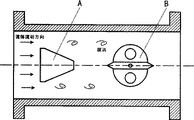
图2为本发明在涡街流量计中的应用原理图;Fig. 2 is the application schematic diagram of the present invention in the vortex flowmeter;
图3为本发明在旋涡进动流量计中的应用原理图。Fig. 3 is a schematic diagram of the application of the present invention in a vortex precession flowmeter.
具体实施方式 Detailed ways
参照图1,固定式自减振流量传感器包括对称固定在平板6两面的检测单元,每个检测单元包括壳体5,为了得到更稳定的信号,一般采用半圆柱形壳体,壳体5具有与平板轴线m-m平行的通孔7,该通孔7中间有一个把通孔等分为上下两个对称区间的凸台,两对称区间的孔径大于凸台处孔径,凸台处有通道8与平板的轴向出线孔4相连通,通孔7的两端分别有弹性膜片1密封,每个区间内分别有压电陶瓷片3和环形绝缘陶瓷块2,压电陶瓷片的一端与弹性膜片1焊接,绝缘陶瓷块2夹在凸台和压电陶瓷片中间,压电陶瓷片3及绝缘陶瓷块2的周边与通孔壁之间留有间隙。上下两个压电陶瓷片的引线相接经通道8从平板出线孔4引出。两个检测单元中四个压电陶瓷片具有相同的尺寸、质量和灵敏度系数,以及相等的预紧力,四个绝缘陶瓷块也同样具有相同的尺寸和质量。Referring to Figure 1, the fixed self-damping flow sensor includes detection units symmetrically fixed on both sides of the
本发明的具体应用参见图2、图3。The specific application of the present invention is referred to Fig. 2, Fig. 3.
图2为本发明在涡街流量计中的应用,为了测量振动流体的流量,把本发明的固定式自减振流量传感器B安装在涡街流量计中旋涡发生体A的后面,传感器与旋涡发生体平行;而对于图3所示的旋涡进动流量计,固定式自减振流量传感器应安装在流道扩展段前端,传感器平板的轴线m-m与管道的轴线垂直相交。Fig. 2 is the application of the present invention in the vortex flowmeter, in order to measure the flow of the vibrating fluid, the fixed self-damping flow sensor B of the present invention is installed in the back of the vortex generator A in the vortex flowmeter, the sensor and the vortex The generating body is parallel; for the vortex precession flowmeter shown in Figure 3, the fixed self-damping flow sensor should be installed at the front end of the flow channel expansion section, and the axis m-m of the sensor plate intersects perpendicularly with the axis of the pipe.
工作时,整个传感器都沉浸在流体中。当旋涡流经传感器时,旋涡产生的交变压力直接作用在两个检测单元的弹性膜片上,使压电陶瓷片产生交变电荷。这时两个检测单元会输出规则的正弦信号S1和S2,这两个信号频率相等,相位相差180°,则两根输出线之间的输出信号为S1-S2,这样即使是在小流量的时候,利用差动输出可以得到较强的检测信号。During operation, the entire sensor is immersed in the fluid. When the vortex flows through the sensor, the alternating pressure generated by the vortex directly acts on the elastic membranes of the two detection units, causing the piezoelectric ceramic sheet to generate alternating charges. At this time, the two detection units will output regular sinusoidal signals S1 and S2. The frequency of these two signals is equal and the phase difference is 180°. When using the differential output, a stronger detection signal can be obtained.
当流体由于管道振动、阀门开启等随机因素的影响,发生流体振荡时,会导致弹性膜片或传感器壳体产生跟随振动。这使检测单元中上下对称的两个压电陶瓷片会分别受压和受拉,于是两个压电陶瓷片会产生相等的正负电荷信号,而当上下两个压电陶瓷片的信号相加时,干扰振动所产生的电荷信号会相互抵消,从而传感器起到了自减振作用。When the fluid oscillates due to random factors such as pipeline vibration and valve opening, it will cause the elastic diaphragm or the sensor housing to generate following vibration. This makes the upper and lower symmetrical piezoelectric ceramics in the detection unit be pressed and pulled respectively, so the two piezoelectric ceramics will generate equal positive and negative charge signals, and when the signals of the upper and lower piezoelectric ceramics are in phase Over time, the charge signals generated by the disturbing vibration will cancel each other out, so the sensor acts as a self-damping vibration.
另外,对于本发明的传感器来说,管道振动属于同向振动,而传感器是采用两个检测单元进行差动检测,因此同向振动的干扰信号会在输出信号S1-S2中相互抵消,这样可以有效地消除管道振动对检测信号的干扰。而对于流体脉动引起的流体振动,它在管道中是一列随着流动方向传播的平面波,它引起的压力以相同的方向同时作用在传感器的两个检测单元上,属于同向振动干扰。同理,传感器的差动检测原理可以消除流体脉动对检测信号的干扰。因此,本发明的流量传感器在流量测量中具有很高的抗干扰性。适用于液体、气体蒸汽等振动流体的流量测量。In addition, for the sensor of the present invention, the pipeline vibration belongs to the same direction vibration, and the sensor uses two detection units for differential detection, so the interference signals of the same direction vibration will cancel each other in the output signal S1-S2, so that Effectively eliminate the interference of pipeline vibration on the detection signal. For the fluid vibration caused by fluid pulsation, it is a series of plane waves propagating with the flow direction in the pipeline, and the pressure caused by it acts on the two detection units of the sensor in the same direction at the same time, which belongs to the same direction vibration interference. Similarly, the differential detection principle of the sensor can eliminate the interference of fluid pulsation on the detection signal. Therefore, the flow sensor of the present invention has high anti-interference ability in flow measurement. It is suitable for flow measurement of vibrating fluids such as liquid, gas and steam.
Claims (5)
Priority Applications (1)
| Application Number | Priority Date | Filing Date | Title |
|---|---|---|---|
| CN 03114983 CN1206517C (en) | 2003-01-17 | 2003-01-17 | Fixed type self vibration damping difference flow sensor |
Applications Claiming Priority (1)
| Application Number | Priority Date | Filing Date | Title |
|---|---|---|---|
| CN 03114983 CN1206517C (en) | 2003-01-17 | 2003-01-17 | Fixed type self vibration damping difference flow sensor |
Publications (2)
| Publication Number | Publication Date |
|---|---|
| CN1431472A true CN1431472A (en) | 2003-07-23 |
| CN1206517C CN1206517C (en) | 2005-06-15 |
Family
ID=4790547
Family Applications (1)
| Application Number | Title | Priority Date | Filing Date |
|---|---|---|---|
| CN 03114983 Expired - Fee Related CN1206517C (en) | 2003-01-17 | 2003-01-17 | Fixed type self vibration damping difference flow sensor |
Country Status (1)
| Country | Link |
|---|---|
| CN (1) | CN1206517C (en) |
Cited By (1)
| Publication number | Priority date | Publication date | Assignee | Title |
|---|---|---|---|---|
| CN114964391A (en) * | 2022-07-28 | 2022-08-30 | 潍坊奥博仪表科技发展有限公司 | Anti-seismic vortex shedding flowmeter probe structure |
-
2003
- 2003-01-17 CN CN 03114983 patent/CN1206517C/en not_active Expired - Fee Related
Cited By (2)
| Publication number | Priority date | Publication date | Assignee | Title |
|---|---|---|---|---|
| CN114964391A (en) * | 2022-07-28 | 2022-08-30 | 潍坊奥博仪表科技发展有限公司 | Anti-seismic vortex shedding flowmeter probe structure |
| CN114964391B (en) * | 2022-07-28 | 2022-11-01 | 潍坊奥博仪表科技发展有限公司 | Anti-seismic vortex shedding flowmeter probe structure |
Also Published As
| Publication number | Publication date |
|---|---|
| CN1206517C (en) | 2005-06-15 |
Similar Documents
| Publication | Publication Date | Title |
|---|---|---|
| JP5394506B2 (en) | Vortex flowmeter with vortex vibration sensor plate | |
| JP2012058237A (en) | Flowmeter for detecting characteristic of fluid | |
| EP3488192B1 (en) | Vortex flowmeter with reduced process intrusion | |
| CN113167609B (en) | Measuring system for measuring flow parameters of a fluid flowing in a pipe | |
| GB2210169A (en) | Apparatus for monitoring or measuring differential fluid presure | |
| CN112654842B (en) | Non-invasive sensor for vortex flowmeter | |
| CN202255473U (en) | Intelligent quake-proof vortex precession flow meter | |
| CN1200253C (en) | Suspension type self vibration damping difference flow sensor | |
| CN1206517C (en) | Fixed type self vibration damping difference flow sensor | |
| CN2597950Y (en) | A fixed self-damping differential flow sensor | |
| CN2594768Y (en) | Self-vibration absorbing floating differential flow pickup | |
| US4572003A (en) | Sidetone generator flowmeter | |
| JP7241885B2 (en) | Vortex flowmeter and flow measurement method | |
| GB2148003A (en) | Measurement of flowrate | |
| Head | A practical pulsation threshold for flowmeters | |
| CN204514403U (en) | A kind of differential pressure mass flowmeter for vortex street | |
| CN115329694A (en) | Fluid flow calculation method and differential pressure type flow sensor | |
| CN223856529U (en) | Sensor for vortex shedding flowmeter | |
| CN1503897A (en) | Vortex Frequency - Flow Meter | |
| CN100424474C (en) | Externally-connected inductive flow sensor | |
| CN221882658U (en) | Vortex street flowmeter | |
| CN2849667Y (en) | Plane type multi-sensitive face flow sensor | |
| RU228528U1 (en) | PIEZOELECTRIC VORTEX DETECTOR | |
| CN2849666Y (en) | External multi-point induction flow sensor | |
| RU222980U1 (en) | HOUSING OF THE FLOW PART OF A VORTEX FLOWMETER WITH TWO ELECTRONIC UNITS |
Legal Events
| Date | Code | Title | Description |
|---|---|---|---|
| C06 | Publication | ||
| PB01 | Publication | ||
| C10 | Entry into substantive examination | ||
| SE01 | Entry into force of request for substantive examination | ||
| C14 | Grant of patent or utility model | ||
| GR01 | Patent grant | ||
| C17 | Cessation of patent right | ||
| CF01 | Termination of patent right due to non-payment of annual fee |
Granted publication date: 20050615 Termination date: 20100219 |