CN1434544A - loop antenna - Google Patents
loop antenna Download PDFInfo
- Publication number
- CN1434544A CN1434544A CN 02102068 CN02102068A CN1434544A CN 1434544 A CN1434544 A CN 1434544A CN 02102068 CN02102068 CN 02102068 CN 02102068 A CN02102068 A CN 02102068A CN 1434544 A CN1434544 A CN 1434544A
- Authority
- CN
- China
- Prior art keywords
- ring
- ring shape
- shape antenna
- mentioned
- conductor plate
- Prior art date
- Legal status (The legal status is an assumption and is not a legal conclusion. Google has not performed a legal analysis and makes no representation as to the accuracy of the status listed.)
- Pending
Links
Images





Landscapes
- Variable-Direction Aerials And Aerial Arrays (AREA)
Abstract
A loop antenna system for a wireless transmission device, having a signal terminal and a ground terminal, comprising: a loop antenna has a toroidal helical wire having a first end coupled to a signal terminal and a second end coupled to a ground terminal.
Description
The invention relates to a kind of ring Shape antenna (Loop Antenna) system,, make ring Shape antenna respond to identical electrical image charge enhanced rad transmission effects particularly relevant for utilizing the earthing conductor plate.
In the radio transmitting device that increases day by day, the size of antenna has very big influence to the efficient of wireless transmission, its size must reach the order of magnitude of radio wavelength, yet in some frequency range, the antenna length that its radio wavelength can provide much larger than radio transmitting device, make wireless transmission efficient reduce, for increasing wireless transmission efficient, must use more complicated antenna and radio circuit, so the cost of radio transmitting device just can improve, the production yield of product descends, and power consumption increases, the advantage of forfeiture wireless transmission.Must utilize earthing conductor plate in the wireless device for improving antenna transmission efficient, and the polarization kenel of driven antenna signal source.
Tradition ring Shape antenna major part is the magnetic couple source excitation, and it is used when thereunder having the environment of grounding plate, and transmission effects is had a strong impact on.
Tradition magnetic couple source ring Shape antenna is applied to the system block diagrams of wireless mouse, as shown in Figure 1, in this operating process in order to the explanation wireless mouse, it comprises radio frequency module 220, comprising amplifier 520, phase-locked loop circuit 450, filter 470, voltage controlled oscillator (voltage control oscillatorVCO) 480.Baseband circuit comprises central processing unit 420, displacement decoder 300, memory 440 (nonvolatile memory such as EEPROM), switch 550.Ring Shape antenna 240 first ends are couple to amplifier 520 signal ends, and ring Shape antenna 240 second ends then are couple to amplifier 520 earth terminals.
When wireless mouse begins to operate, central processing unit 420 is read the wireless transfer channel frequency from memory 440, the sampling frequency of optical detector 310, and the identification code of wireless mouse (identificationcode), it is used so that host computer identical traffic frequency in identical transmission region is distinguished different wireless mouses, so at each wireless mouse of same host computer one identification code is arranged.When the wireless mouse opening power is brought into use, the computer peripheral identification code that memory 440 upgrades in order to the record wireless mouse.
Central processing unit 420 is controlled the wireless transfer channel frequency by the modulating frequency of control phase-locked loop circuit 450.Central processing unit 420 reads set transmission channel frequency data by memory 440, again the transmission channel frequency data is write phase-locked loop circuit 450, make its generation have the carrier signal of transmission channel frequency, can press the transmission channel frequency data that channel selecting key 500 changes in the memory 440 by the user.
Central processing unit 420 provides switch and displacement data to modulator 560, modulator 560 can be VCXO (VCXO), it is connected with oscillating crystal (crystal), can obtain the reference frequency that to modulate, can reach frequency shift keying (frequency shift keying FSK) modulator, when reference frequency produces modulating frequency by VCXO, phase-locked loop circuit 450, filter 470 and voltage controlled oscillator 480 produce a feedback loop, this loop can form a frequency synthesizer circuit, the radio-frequency carrier signal (carrier) that voltage controlled oscillator 480 produces an accurate frequency is loaded with a modulation signal, and this radio-frequency carrier signal exports circular ring Shape antenna 241 to via amplifier 520.The reference frequency modulation signal of modulator 560 is by the resonant capacitor that switches reference frequency oscillator (not shown), reference frequency changes with resonant capacitor, frequency shift keying modulation just, the signal that its frequency is switched are exactly the enciphered data of wireless mouse operation.Filter 470 must have enough frequency ranges to make it can catch up with the modulation of reference frequency.
(this metal desktop can be considered an earthing conductor plate) can cause magnetic couple source (Magnetic dipole source) to be offset because of metallic plate on a metal desktop if use when wireless mouse, influences the input impedance of loop aerial 240, causes transmission range to shorten.Its framework as shown in Figure 2, ring Shape antenna 240 uses on earthing conductor plate 230, ring Shape antenna 240 first ends are couple to amplifier 520 signal ends of radio frequency module 220, second end is couple to radio frequency module 220 earth terminals; And ring Shape antenna 240 is positioned at earthing conductor plate 230 tops, and is parallel near earthing conductor plate 230.The sense of current of ring Shape antenna 240 is parallel to metallic plate 230, because earthing conductor plate 230 is good conductors, for the tangential direction electric field of keeping earthing conductor plate 230 is zero boundary condition (boundary condition), so this earthing conductor plate 230 can be considered as the opposite mirror current source of a direction equivalently, it produces the magnetic couple source in the direction opposite ring Shape antenna 240 generations in mirror image magnetic couple source, as shown in Figure 3, thus mirror image magnetic couple source can weaken the radiation intensity of ring Shape antenna 240.Especially general wireless mouse all is to press close to desktop to use, the very big distance of can not being separated by between mouse and the metal desktop (with respect to wavelength), and under this situation, ring Shape antenna 240 is near more with the distance D of earthing conductor plate 230, and its destructive interference effect is strong more.
In view of this, the present invention then proposes a kind of ring Shape antenna system, is applicable to that a radio transmitting device has signal end and earth terminal, and it is in order to transmit a transmission signal, and it comprises: (a) earthing conductor plate, and it is coupled to an earth terminal; With (b) ring Shape antenna, this ring Shape antenna be by a spiral wire winding ring around and form a ring body.This spiral coiling has one first end and is coupled to this earth terminal, and this ring body has a principal axis A X1, a principal axis A X2, and principal axis A X1 is perpendicular to this earthing conductor plate, and inferior principal axis A X2 is parallel to this earthing conductor plate.Long-range during greater than this ring Shape antenna size when the rf wave of this transmission signal, the magnetic current of this ring Shape antenna is to distribute along inferior principal axis A X2, and the eelctric dipole of this ring Shape antenna is to distribute along this principal axis A X1, and perpendicular to this earthing conductor plate.
Description of drawings
Fig. 1 represents that traditional ring Shape antenna is applied to the system block diagrams of wireless mouse.
Fig. 2 represents the ring Shape antenna system schematic of conventional wireless mouse.
Fig. 3 represents the magnetic couple source and the mirror image magnetic couple source schematic diagram of traditional ring Shape antenna.
Fig. 4 represents embodiment of the invention ring Shape antenna system schematic.
Fig. 5 represents the stereogram of anchor ring spiral coiling in the embodiment of the invention " circular ring surface, the circular cross-section " ring Shape antenna.
Fig. 6 represents the galvanic couple source and the mirror image galvanic couple source schematic diagram of embodiment of the invention ring Shape antenna.
Fig. 7 A-7C represents the embodiment of the invention " circular ring surface " ring Shape antenna application schematic diagram.
Fig. 8 represents the stereogram of anchor ring spiral coiling in the embodiment of the invention " circular ring surface, the square cross section " ring Shape antenna.
Fig. 9 represents the embodiment of the invention " square anchor ring, circular cross-section " ring Shape antenna system schematic.
Figure 10 represents the stereogram of anchor ring spiral coiling in the embodiment of the invention " square anchor ring, the square cross section " ring Shape antenna.
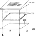
Figure 11 A-11C represents the embodiment of the invention " quadrangle anchor ring " ring Shape antenna application schematic diagram.Symbol description 200,201~circular ring body; 202~quadrangle ring body; 200a~circular cross-section; 220~radio frequency module; 230~earthing conductor plate; 240~ring Shape antenna; 241,242~ring Shape antenna; 250~wireless mouse; 300~displacement decoder; 310~optical detector; 420~central processing unit; 440~memory; 450~phase-locked loop circuit; 470~filter; 480~voltage controlled oscillator; 500~channel selecting key; 520~amplifier; 550~switch; 560~modulator.
Embodiment
The ring Shape antenna system of present embodiment mainly is to utilize the mirror image galvanic couple source of the galvanic couple source of the coiling of spiral in the ring Shape antenna and earthing conductor plate induction equidirectional to strengthen aerial radiation intensity.
Because the mirror image magnetic couple source of responding to perpendicular to the magnetic couple source of earthing conductor plate is electrically opposite, weakens antenna radiation capability.(duality of electromagnetic) can learn by double electromagnetic, utilize the electromagnetic field of magnetic couple source ring Shape antenna, electric field is replaced by magnetic field, magnetic field is replaced by the rightabout electric field, magnetic capacity is replaced by dielectric constant, dielectric constant is replaced by the magnetic conduction constant, and equivalent magnetic current (magnetic current) replaces electric current (electric current), just can obtain the electromagnetic field of galvanic couple source (electric dipole source) ring Shape antenna.
First embodiment
The galvanic couple source can excite by the magnetic current of anchor ring spiral coiling (toroidal helix wire), shown in circular ring Shape antenna 241 among Fig. 4, disclose the embodiment of " circular ring surface; circular cross-section ", the electric current that just replaces the magnetic dipole ring Shape antenna with magnetic current, magnetic current is proportional to the flux change rate of spiral coiling, and Fig. 5 represents the stereogram of anchor ring spiral coiling in the circular ring Shape antenna 241, circular ring Shape antenna 241 be by a spiral wire winding ring around and form a circular ring body (toroid) 200.When overlooking from the top, this circle ring body 200 has a circular ring surface, and when analysing and observe from side side, this circle ring body 200 has a circular cross-section 200a.Can comprise a ring-type circular cross-section magnetic conductive iron (as ferrite core) in this circle ring body 200, or the hollow space of circular cross-section.Circular ring body 200 has a principal axis A X1, a principal axis A X2, a main radius R, and a radius r.Principal axis A X1 is perpendicular to the plane at circular ring body 200 places, and inferior principal axis A X2 is that main radius R forms a circle, and circular ring body 200 is the curved surfaces that are made of distance time principal axis A X2 certain distance r.When magnetic flux density is even distribution, magnetic current can equivalence be considered as distributing along inferior principal axis A X2, and just the CURRENT DISTRIBUTION with the magnetic dipole ring Shape antenna is consistent, and eelctric dipole is then consistent with principal axis A X1.Being parallel to circular ring Shape antenna 241 belows has an earthing conductor plate 230, when the wavelength of transmission signal radio frequency much larger than circular ring Shape antenna 241, the magnetic current ring Shape antenna can equivalence become a galvanic couple source ring Shape antenna, and perpendicular to earthing conductor plate 230.As shown in Figure 6, be zero boundary condition in order to satisfy earthing conductor plate 230 tangential direction electric fields, so earthing conductor plate 230 can be regarded as the mirror image galvanic couple source of an equivalence, and mirror image galvanic couple source is identical with the direction in galvanic couple source; So the mirror image power supply has the effect of reinforcement to the radiated electric field of circular ring Shape antenna 241.When the distance D of circular ring Shape antenna 241 and earthing conductor plate 230 is more little, its stiffening effect is good more, and radiated electric field is during more near conductor plate 230, and circular ring Shape antenna 2411 radiation intensity are all the more strong.
Second embodiment
Fig. 8 represents the stereogram of anchor ring spiral coiling in the circular ring Shape antenna 241, discloses the embodiment of " circular ring surface, quadrangular section ".Circular ring Shape antenna 241 be by the spiral wire winding ring around and form circular ring body (toroid) 201, when overlooking from the top, this circle ring body 200 has a circular ring surface, when analysing and observe from side side, this circle ring body 200 has a quadrangular section 200b.In this circle ring body 201, can comprise a ring-type quadrangular section magnetic conductive iron, or the hollow space of a quadrangular section.Circular ring body 201 has a principal axis A X1, a principal axis A X2, a main radius R, and the width w of quadrangular section, height h.Principal axis A X1 is perpendicular to the plane at circular ring body 201 places, inferior principal axis A X2 is that main radius R forms a circle, circular ring body 201 is to have the quadrangular section of width w height h by one, apart from principal axis A X1 certain distance R (just main radius), and the curved surface that constitutes around principal axis A X1 rotation.
As shown in Figure 7, be an embodiment who uses the wireless mouse of circular ring Shape antenna 241, earthing conductor plate 230 is positioned at wireless mouse 250 bottoms, circular ring Shape antenna 241 first ends are couple to radio frequency module 220 signal ends, its second end is couple to radio frequency module 220 earth terminals, circular ring Shape antenna 241 is positioned at earthing conductor plate 230 tops, and is parallel near earthing conductor plate 230.Earthing conductor plate 230 is couple to the ground connection of radio frequency module 220, and just radio frequency module 220 has common ground connection with metallic plate 230.
Because earthing conductor plate 230 is good conductors, for the tangential direction electric field of keeping earthing conductor plate 230 is zero, the effect of earthing conductor plate 230 can be considered as be one identical electrically and etc. the mirror image galvanic couple source of the quantity of electric charge.The magnetic current direction of circular ring Shape antenna 241 is to be parallel to metallic plate 230, can be same as the galvanic couple source that circular ring Shape antenna 241 produces so the mirror image magnetic current that direction is identical produces the direction in mirror image galvanic couple source, so the radiation intensity of circular ring Shape antenna 241 can be strengthened in mirror image galvanic couple source.
Shown in Fig. 7 B, be circular ring-like antenna wireless mouse applications in another embodiment of a metal computer desktop environment, and suppose the area of the area of this metal computer desktop, so the desktop of computer desk can be considered as an earthing conductor plate 230 much larger than loop aerial 241.Circular ring Shape antenna 241 first ends are couple to the signal end of radio frequency module 220, and its second end is couple to the earth terminal of radio frequency module 220.When this wireless mouse placed on this metal computer desktop, this circle ring Shape antenna 241 was positioned at earthing conductor plate 230 tops, and parallel near earthing conductor plate 230 (metal computer desktop).
Shown in Fig. 7 C, be that circular ring Shape antenna 241 is applied to another embodiment in the computer system wireless signal receiving terminal.Earthing conductor plate 230 is positioned at computer 600, circular ring Shape antenna 241 first ends are couple to the signal end of radio frequency module 220, its second end is couple to the earth terminal of radio frequency module 220, and circular ring Shape antenna 241 is positioned at earthing conductor plate 230 tops, and is parallel near earthing conductor plate 230.Earthing conductor plate 230 is couple to the ground connection of radio frequency module 220, and just radio frequency module 220 has common ground connection with metallic plate 230.
The 3rd embodiment
Fig. 9 represents the stereogram of anchor ring spiral coiling in the ring-like antenna 242 of quadrangle, discloses the embodiment of " quadrangle anchor ring, circular cross-section ".The ring-like antenna 242 of quadrangle is by helical coil coiled one quadrangle ring body 202, and when overlooking from the top, this circle ring body 202 has a quadrangle anchor ring, and when analysing and observe from side side, this quadrangle shape ring body 202 has a circular cross-section 202a.The magnetic conductive iron that can comprise a circular cross-section in the quadrangle ring body 202, or the hollow space of a circular cross-section.As shown in figure 10, quadrangle ring body 202 has a principal axis A X1, and a principal axis A X2, inferior principal axis A X2 are that a rectangle has long limit a, minor face b, and the width w in cross section, height h.Principal axis A X1 is perpendicular to the plane at quadrangle ring body 202 places, inferior principal axis A X2 is formed a rectangle by long limit a and minor face b, and quadrangle ring body 202 cross sections are to be a circle, perpendicular to inferior principal axis A X2, its centre of form (centroid) moves the curved surface that is produced along time principal axis A X2.
The 4th embodiment
Figure 10 represents the stereogram of spiral coiling in the ring-like antenna 242 of quadrangle, discloses the embodiment of " quadrangle anchor ring, quadrangular section ".The ring-like antenna 242 of quadrangle is by helical coil coiled one quadrangle ring body 202, and when overlooking from the top, this circle ring body 202 has a quadrangle anchor ring, and when analysing and observe from side side, this quadrangle ring body 202 has a quadrangular section 202b.The magnetic conductive iron that can comprise a quadrangular section in this quadrangle ring body 202, or the hollow space of a quadrangular section.Quadrangle ring body 202 has a principal axis A X1, and a principal axis A X2, inferior principal axis A X2 are that a rectangle has long limit a, minor face b, and the width w in cross section, height h.Principal axis A X1 is perpendicular to the plane at quadrangle ring body 202 places, inferior principal axis A X2 is formed a rectangle by long limit a and minor face b, quadrangle ring body 202 is to have the quadrangular section of width w height h by one, perpendicular to inferior principal axis A X2, its type heart (centroid) moves the curved surface that is produced along time principal axis A X2.
Shown in Figure 11 A, be an embodiment who uses the Wireless Keyboard of the ring-like antenna 242 of quadrangle, ring-like antenna 242 first ends of quadrangle are couple to radio frequency module 220 signal ends, and its second end is couple to radio frequency module 220 earth terminals.This Wireless Keyboard 260 lower casings top is provided with an earthing conductor plate 230, and the ring-like antenna 242 of quadrangle is to be arranged between these Wireless Keyboard 260 upper casings and the earthing conductor plate 230, make the ring-like antenna 242 of this quadrangle be positioned at earthing conductor plate 230 tops, and essence is abreast near earthing conductor plate 230.Earthing conductor plate 230 is couple to the ground connection of radio frequency module 220, and just radio frequency module 220 has common ground connection with metallic plate 230.
Because earthing conductor plate 230 is good conductors, for the tangential direction electric field of keeping earthing conductor plate 230 is zero, the effect of earthing conductor plate 230 can be considered as be one identical electrically and etc. the mirror image galvanic couple source of the quantity of electric charge.The magnetic current direction of the ring-like antenna 242 of quadrangle is to be parallel to metallic plate 230, can be same as the galvanic couple source that the ring-like antenna 242 of quadrangle produces so the mirror image magnetic current that direction is identical produces the direction in mirror image galvanic couple source, so the radiation intensity of the ring-like antenna 242 of quadrangle can be strengthened in mirror image galvanic couple source.
Shown in Figure 11 B, be that the ring-like antenna wireless keyboard applications of quadrangle is in another embodiment of a metal computer desktop environment, the ring-like antenna 242 of this quadrangle is to be arranged between these Wireless Keyboard 260 upper casings and the lower casing [not shown], and suppose the area of the area of this metal computer desktop, so the desktop of computer desk can be considered as earthing conductor plate 230 much larger than ring Shape antenna 242.Ring-like antenna 242 first ends of quadrangle are couple to the signal end of radio frequency module 220, and its second end is couple to the earth terminal of radio frequency module 220.When this Wireless Keyboard placed on this metal computer desktop, the ring-like antenna 242 of this quadrangle was positioned at earthing conductor plate 230 tops, and essence is abreast near earthing conductor plate 230 (metal computer desktop).
Shown in Figure 11 C, be that the ring-like antenna 242 of quadrangle is applied to another embodiment in the computer system wireless signal receiving terminal.Earthing conductor plate 230 is positioned at computer 600, ring-like antenna 242 first ends of quadrangle are couple to the signal end of radio frequency module 220, its second end is couple to the earth terminal of radio frequency module 220, and the ring-like antenna 242 of quadrangle is positioned at earthing conductor plate 230 tops, and is parallel near earthing conductor plate 230.Earthing conductor plate 230 is couple to the ground connection of radio frequency module 220, and just radio frequency module 220 has common ground connection with metallic plate 230.
Though the present invention discloses as above with a preferred embodiment; right its is not in order to qualification the present invention, any insider, without departing from the spirit and scope of the present invention; when can doing a little change and retouching, so protection scope of the present invention is as the criterion when looking the accompanying Claim person of defining.
Claims (16)
1. a ring Shape antenna system is applicable to a radio transmitting device, has a signal end and an earth terminal, and it comprises:
One ring Shape antenna has a ring-like spiral coiling, and it has, and one first end is coupled to above-mentioned signal end and one second end is coupled to above-mentioned earth terminal.
2. ring Shape antenna as claimed in claim 1 system, it is circular looking anchor ring in the wherein above-mentioned ring-like spiral coiling, and to analyse and observe the cross section be circular.
3. ring Shape antenna as claimed in claim 2 system, wherein above-mentioned ring-like spiral coiling inside comprises a magnetic conductive iron.
4. ring Shape antenna as claimed in claim 1 system, it is circular looking anchor ring in the wherein above-mentioned ring-like spiral coiling, and to analyse and observe the cross section be quadrangle.
5. ring Shape antenna as claimed in claim 4 system, wherein above-mentioned ring-like spiral coiling inside comprises a magnetic conductive iron.
6. ring Shape antenna as claimed in claim 1 system, looking anchor ring in the wherein above-mentioned ring-like spiral coiling is quadrangle, and to analyse and observe the cross section be quadrangle.
7. ring Shape antenna as claimed in claim 6 system, wherein above-mentioned ring-like spiral coiling inside comprises a magnetic conductive iron.
8. ring Shape antenna as claimed in claim 1 system, wherein above-mentioned radio transmitting device is a Wireless Keyboard.
9. ring Shape antenna as claimed in claim 8 system, wherein above-mentioned Wireless Keyboard inside comprises an earthing conductor plate, and it is coupled to above-mentioned earth terminal, and parallel in fact near above-mentioned ring Shape antenna.
10. ring Shape antenna as claimed in claim 1 system, wherein above-mentioned radio transmitting device is a wireless mouse.
11. ring Shape antenna as claimed in claim 10 system, wherein above-mentioned wireless mouse inside comprises an earthing conductor plate, and it is coupled to above-mentioned earth terminal, and parallel in fact near above-mentioned ring Shape antenna.
12. a radio transmitting device, it is in order to transmit a transmission signal, and it comprises:
One earthing conductor plate, it is coupled to an earth terminal; With
One ring Shape antenna, comprise by a spiral wire winding ring around and the ring body that forms, this spiral coiling has one first end and is coupled to this earth terminal, this ring body has a principal axis A X1, a principal axis A X2, principal axis A X1 is perpendicular to this earthing conductor plate, and inferior principal axis A X2 is parallel to this earthing conductor plate;
Long-range during greater than this ring Shape antenna size when the rf wave of this transmission signal, the magnetic current of this ring Shape antenna is to distribute along inferior principal axis A X2, and the eelctric dipole of this ring Shape antenna is to distribute along this principal axis A X1, and perpendicular to this earthing conductor plate.
13. radio transmitting device as claimed in claim 12, more comprise a upper casing and a lower casing, and this earthing conductor plate is to be arranged at this lower casing top, and this ring Shape antenna is to be arranged between this upper casing and this earthing conductor plate, makes this ring Shape antenna be positioned at this earthing conductor plate top.
14. radio transmitting device as claimed in claim 12 more comprises a upper casing and a lower casing, this ring Shape antenna is to be arranged between this upper casing and this lower casing.
15. radio transmitting device as claimed in claim 12, wherein the anchor ring of this ring body is circular, and the cross section of this ring body is circular.
16. radio transmitting device as claimed in claim 12, wherein above-mentioned ring-like spiral coiling inside comprises a magnetic conductive iron.
Priority Applications (1)
| Application Number | Priority Date | Filing Date | Title |
|---|---|---|---|
| CN 02102068 CN1434544A (en) | 2002-01-21 | 2002-01-21 | loop antenna |
Applications Claiming Priority (1)
| Application Number | Priority Date | Filing Date | Title |
|---|---|---|---|
| CN 02102068 CN1434544A (en) | 2002-01-21 | 2002-01-21 | loop antenna |
Publications (1)
| Publication Number | Publication Date |
|---|---|
| CN1434544A true CN1434544A (en) | 2003-08-06 |
Family
ID=27627454
Family Applications (1)
| Application Number | Title | Priority Date | Filing Date |
|---|---|---|---|
| CN 02102068 Pending CN1434544A (en) | 2002-01-21 | 2002-01-21 | loop antenna |
Country Status (1)
| Country | Link |
|---|---|
| CN (1) | CN1434544A (en) |
Cited By (2)
| Publication number | Priority date | Publication date | Assignee | Title |
|---|---|---|---|---|
| CN102142601A (en) * | 2010-11-26 | 2011-08-03 | 深圳市麦捷微电子科技股份有限公司 | Miniature radio frequency identification reading antenna |
| CN102017290B (en) * | 2008-03-26 | 2014-12-03 | 道康股份公司 | Modified loop antenna |
-
2002
- 2002-01-21 CN CN 02102068 patent/CN1434544A/en active Pending
Cited By (3)
| Publication number | Priority date | Publication date | Assignee | Title |
|---|---|---|---|---|
| CN102017290B (en) * | 2008-03-26 | 2014-12-03 | 道康股份公司 | Modified loop antenna |
| CN102142601A (en) * | 2010-11-26 | 2011-08-03 | 深圳市麦捷微电子科技股份有限公司 | Miniature radio frequency identification reading antenna |
| CN102142601B (en) * | 2010-11-26 | 2014-03-12 | 深圳市麦捷微电子科技股份有限公司 | Miniature radio frequency identification reading antenna |
Similar Documents
| Publication | Publication Date | Title |
|---|---|---|
| CN1149713C (en) | Rotating field antenna with magnetically coupled quadrature loop | |
| JP4720348B2 (en) | Antenna for RF-ID reader / writer device, RF-ID reader / writer device using the antenna, and RF-ID system | |
| EP1628360B1 (en) | Small rectenna | |
| US7446729B2 (en) | Loop antenna unit and radio communication medium processor | |
| US6600459B2 (en) | Antenna | |
| EP2118965B1 (en) | Self-resonant electrically small antenna | |
| CA2702284C (en) | Coil antenna and non-contact information medium | |
| US6642897B2 (en) | Tuning techniques for a slot antenna | |
| CN101052775B (en) | RFID near field microstrip antenna | |
| CN105914447B (en) | Resonance circuit and antenna assembly | |
| CN1577965A (en) | Bifrequency shared antenna apparatus | |
| JP2006311239A (en) | Wireless IC tag device and RFID system | |
| JPWO2005053095A1 (en) | Information processing apparatus including non-contact reader and / or writer, and coil antenna for magnetic coupling | |
| CN101179158A (en) | RFID tag reading system and RFID tag reading method | |
| KR100680711B1 (en) | Small antenna with improved bandwidth and small rectenna used for wireless recognition and wireless sensor transponders | |
| Forouzannezhad et al. | Multiband compact antenna for near‐field and far‐field RFID and wireless portable applications | |
| US11329697B2 (en) | Multi-layer electromagnetic coupler arrangement | |
| CN103367879B (en) | A kind of Small-size end-fire directional antenna | |
| US20110057851A1 (en) | Planar antenna and electromagnetic band gap structure thereof | |
| JP2008203996A (en) | Substrate, and system for confirming presence position and frequency response characteristics of substrate | |
| JP2015136013A (en) | Antenna device | |
| US7893887B2 (en) | Antenna for RFID device reader, and method of use | |
| CN1434544A (en) | loop antenna | |
| US6822614B2 (en) | Loop antenna | |
| CN102820535A (en) | Near-field radio frequency identification (RFID) reader plane opening dual-ring antenna for ultra high frequency (UHF) band |
Legal Events
| Date | Code | Title | Description |
|---|---|---|---|
| C10 | Entry into substantive examination | ||
| SE01 | Entry into force of request for substantive examination | ||
| C06 | Publication | ||
| PB01 | Publication | ||
| C10 | Entry into substantive examination | ||
| SE01 | Entry into force of request for substantive examination | ||
| C02 | Deemed withdrawal of patent application after publication (patent law 2001) | ||
| WD01 | Invention patent application deemed withdrawn after publication |