CN1435687A - Automatic sampling machine - Google Patents
Automatic sampling machine Download PDFInfo
- Publication number
- CN1435687A CN1435687A CN03103399A CN03103399A CN1435687A CN 1435687 A CN1435687 A CN 1435687A CN 03103399 A CN03103399 A CN 03103399A CN 03103399 A CN03103399 A CN 03103399A CN 1435687 A CN1435687 A CN 1435687A
- Authority
- CN
- China
- Prior art keywords
- fluid path
- hole
- spray
- diverter valve
- sample
- Prior art date
- Legal status (The legal status is an assumption and is not a legal conclusion. Google has not performed a legal analysis and makes no representation as to the accuracy of the status listed.)
- Granted
Links
Images

Classifications
-
- G—PHYSICS
- G01—MEASURING; TESTING
- G01N—INVESTIGATING OR ANALYSING MATERIALS BY DETERMINING THEIR CHEMICAL OR PHYSICAL PROPERTIES
- G01N35/00—Automatic analysis not limited to methods or materials provided for in any single one of groups G01N1/00 - G01N33/00; Handling materials therefor
- G01N35/10—Devices for transferring samples or any liquids to, in, or from, the analysis apparatus, e.g. suction devices, injection devices
- G01N35/1095—Devices for transferring samples or any liquids to, in, or from, the analysis apparatus, e.g. suction devices, injection devices for supplying the samples to flow-through analysers
- G01N35/1097—Devices for transferring samples or any liquids to, in, or from, the analysis apparatus, e.g. suction devices, injection devices for supplying the samples to flow-through analysers characterised by the valves
-
- G—PHYSICS
- G01—MEASURING; TESTING
- G01N—INVESTIGATING OR ANALYSING MATERIALS BY DETERMINING THEIR CHEMICAL OR PHYSICAL PROPERTIES
- G01N30/00—Investigating or analysing materials by separation into components using adsorption, absorption or similar phenomena or using ion-exchange, e.g. chromatography or field flow fractionation
- G01N30/02—Column chromatography
- G01N30/04—Preparation or injection of sample to be analysed
- G01N30/24—Automatic injection systems
-
- G—PHYSICS
- G01—MEASURING; TESTING
- G01N—INVESTIGATING OR ANALYSING MATERIALS BY DETERMINING THEIR CHEMICAL OR PHYSICAL PROPERTIES
- G01N30/00—Investigating or analysing materials by separation into components using adsorption, absorption or similar phenomena or using ion-exchange, e.g. chromatography or field flow fractionation
- G01N30/02—Column chromatography
- G01N30/04—Preparation or injection of sample to be analysed
- G01N30/16—Injection
- G01N30/20—Injection using a sampling valve
- G01N2030/207—Injection using a sampling valve with metering cavity, e.g. sample loop
-
- Y—GENERAL TAGGING OF NEW TECHNOLOGICAL DEVELOPMENTS; GENERAL TAGGING OF CROSS-SECTIONAL TECHNOLOGIES SPANNING OVER SEVERAL SECTIONS OF THE IPC; TECHNICAL SUBJECTS COVERED BY FORMER USPC CROSS-REFERENCE ART COLLECTIONS [XRACs] AND DIGESTS
- Y10—TECHNICAL SUBJECTS COVERED BY FORMER USPC
- Y10T—TECHNICAL SUBJECTS COVERED BY FORMER US CLASSIFICATION
- Y10T137/00—Fluid handling
- Y10T137/0318—Processes
- Y10T137/0402—Cleaning, repairing, or assembling
- Y10T137/0491—Valve or valve element assembling, disassembling, or replacing
- Y10T137/0508—Ball valve or rotary ball valve
-
- Y—GENERAL TAGGING OF NEW TECHNOLOGICAL DEVELOPMENTS; GENERAL TAGGING OF CROSS-SECTIONAL TECHNOLOGIES SPANNING OVER SEVERAL SECTIONS OF THE IPC; TECHNICAL SUBJECTS COVERED BY FORMER USPC CROSS-REFERENCE ART COLLECTIONS [XRACs] AND DIGESTS
- Y10—TECHNICAL SUBJECTS COVERED BY FORMER USPC
- Y10T—TECHNICAL SUBJECTS COVERED BY FORMER US CLASSIFICATION
- Y10T137/00—Fluid handling
- Y10T137/2496—Self-proportioning or correlating systems
-
- Y—GENERAL TAGGING OF NEW TECHNOLOGICAL DEVELOPMENTS; GENERAL TAGGING OF CROSS-SECTIONAL TECHNOLOGIES SPANNING OVER SEVERAL SECTIONS OF THE IPC; TECHNICAL SUBJECTS COVERED BY FORMER USPC CROSS-REFERENCE ART COLLECTIONS [XRACs] AND DIGESTS
- Y10—TECHNICAL SUBJECTS COVERED BY FORMER USPC
- Y10T—TECHNICAL SUBJECTS COVERED BY FORMER US CLASSIFICATION
- Y10T137/00—Fluid handling
- Y10T137/4456—With liquid valves or liquid trap seals
- Y10T137/4621—Seal for relatively movable valving parts
- Y10T137/4628—Horizontally moving valve
- Y10T137/4636—Rotary
-
- Y—GENERAL TAGGING OF NEW TECHNOLOGICAL DEVELOPMENTS; GENERAL TAGGING OF CROSS-SECTIONAL TECHNOLOGIES SPANNING OVER SEVERAL SECTIONS OF THE IPC; TECHNICAL SUBJECTS COVERED BY FORMER USPC CROSS-REFERENCE ART COLLECTIONS [XRACs] AND DIGESTS
- Y10—TECHNICAL SUBJECTS COVERED BY FORMER USPC
- Y10T—TECHNICAL SUBJECTS COVERED BY FORMER US CLASSIFICATION
- Y10T436/00—Chemistry: analytical and immunological testing
- Y10T436/11—Automated chemical analysis
Landscapes
- Physics & Mathematics (AREA)
- Health & Medical Sciences (AREA)
- Life Sciences & Earth Sciences (AREA)
- Chemical & Material Sciences (AREA)
- Analytical Chemistry (AREA)
- Biochemistry (AREA)
- General Health & Medical Sciences (AREA)
- General Physics & Mathematics (AREA)
- Immunology (AREA)
- Pathology (AREA)
- Sampling And Sample Adjustment (AREA)
- Automatic Analysis And Handling Materials Therefor (AREA)
Abstract
在一种直喷式自动取样机中,取样针插入一个喷射孔中,取样针中具有利用一个泵的抽吸力而从样品容器中收集到的液体样品。然后,转动一个流体路径转换阀以切换流体路径,使一种流动相流体穿过一个环圈,从而将所收集的样品引入一个柱管中。该喷射孔与流体路径转换阀直接结合在一起。
In a direct injection type autosampler, a sampling needle having a liquid sample collected from a sample container by the suction force of a pump is inserted into an injection hole. Then, a fluid path switching valve is turned to switch the fluid path so that a mobile phase fluid passes through a loop to introduce the collected sample into a column tube. The spray orifice is directly integrated with the fluid path switching valve.
Description
Technical field
The present invention relates to a kind of automatic sampler, for example, each sample is automatically sent into a kind of automatic sampler used in the liquid chromatograph.
Background technology
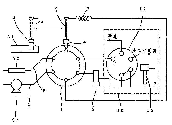
Fig. 3 has shown the fluid path as the automatic sampler vitals in the used correlation technique of liquid chromatograph.
In Fig. 3, automatic sampler has a fluid path that has 6 outlets and 2 positions and switches rotary valve 1, this valve 1 has at regular intervals 6 outlets of arranging, and two path positions that two the every adjacent outlets in 6 outlets are interconnected.When fluid path diverter valve 1 was rotated, one of them path position just moved to another path position with the conversion fluid path.
Be arranged in each sampling receptacle 3 on the platform 31 and all comprise a kind of fluid sample to be analyzed.Fluid sample is drawn and collected to sampling probe 5 from a selected sampling receptacle 3.Sampling probe 5 links to each other with pump 2 by the flexible duct 6 (hereinafter being called " ring ") and the fluid path diverter valve 1 of circling round, and like this, pump 2 just applies suction force to sampling probe 5.By the automatic drive mechanism sampling probe 5 that does not show in by position shown in the dotted line among Fig. 3 (sample position) behind the imbitition sample, sampling probe 5 moves to the position (eject position) by the solid line representative among Fig. 3.In this eject position, sampling probe 5 is inserted in the spray-hole 4.After the insertion, with sampling probe 5 liquid-tight seals in spray-hole 4.
A kind of dynamic bit phase liquid that is used for liquid chromatograph enters fluid path diverter valve 1 from liquid delivery pump 91 beginnings via moving phase liquid delivery path 7, and further flows to into column jecket 92 by a tubulose upstream side fluid path 8.
Automatic sampler also comprises a rinsing mechanism 10, and this rinsing mechanism 10 comprises 11 and rinsing liquid outlets 12 of another valve (low pressure valve).Before next sample was analyzed, 10 pairs of sample liquids from sampling probe 5 grades of rinsing mechanism played the important effect that rinses, to eliminate the pollution by previous sample was brought.Because rinsing mechanism 10 is not directly related with content of the present invention, therefore, has just omitted the detailed description to rinsing mechanism 10 herein.
Is to be undertaken by following order by automatic sampler to the introducing of each sample:
(1) working by the path of the fluid path diverter valve 1 of the solid line representative among Fig. 3, and sampling probe 5 is placed under the situation of sample position, immerses in the sampling receptacles 3 sampling probe 5 and actuated pump 2, like this, just can suck and collect the predetermined amount of liquid sample.The fluid sample that is collected mainly remains in the ring 6.
(2) sampling probe 5 is moved to eject position and be inserted in the spray-hole 4.
(3) rotate 60 degree and make when being worked by the represented path of the dotted line among Fig. 3 in fluid path diverter valve 1, the moving phase liquid of being carried by liquid delivery pump 91 enters column jecket 92 by spray-hole 4, pipeline 41 and the tubulose upstream side fluid path 8 that continuous stream through moving phase liquid delivery path 7, ring 6, sampling probe 5, wherein is inserted with sampling probe 5.Like this, mainly be kept in the ring 6 fluid sample just by carrying to column jecket 92 and be carried out analysis.
(4) fluid path diverter valve 1 is gone back to, and carry out rinsing by rinsing mechanism 10 and handle (this content not being described in detail among the application), for the collection of next sample is prepared.Then, this automatic sampler is waited for and is collected next sample.
Automatic sampler shown in Fig. 3 is called as " direct injection automatic sampler ", and this is because the sample of being drawn and being collected by sampling probe 5 can be introduced directly in the column jecket 92.In the direct injection automatic sampler of correlation technique, spray-hole 4 is arranged and is interconnected by pipeline 41 with fluid path diverter valve 1 is independent mutually.As mentioned above, because fluid sample is essential by pipeline 41, the internal capacity of pipeline 41 forms dead volume.Therefore, the defective that just has the diffusion of sample peak value.In addition, if having pipe adapter in the path of sample flow warp, sample is easy to usually to remain in and causes cross pollution in the slight gap at pipe adapter place.Therefore, need reduce the quantity of pipe adapter as far as possible.
Summary of the invention
The present invention improves the problem that correlation technique exists.An object of the present invention is to provide a kind of automatic sampler, reduce the quantity of sample flow in this automatic sampler as far as possible through the internal capacity and the pipe adapter in path.
For addressing the above problem, automatic sampler according to the present invention comprises a spray-hole and a fluid path diverter valve (flow path-switching valve), wherein, the spray-hole in the sampler directly links to each other mutually with fluid path diverter valve, and does not insert any pipeline betwixt.That is to say that automatic sampler of the present invention is to have a spray-hole to reach the toroidal swirl type automatic sampler that forms a whole fluid path diverter valve with this spray-hole.
Therefore, reduced the pipe adapter number in the path of sample flow warp, and reduced dead volume, thereby reduced cross pollution.
Description of drawings
Fig. 1 is the view of one embodiment of the present of invention;
Fig. 2 has shown the concrete structure of the embodiment of the invention;
An example that has shown the automatic sampler in the correlation technique among Fig. 3.
Embodiment
One embodiment of the present of invention have been shown among Fig. 1.Fluid path shown in Fig. 1 is the pith of direct injection automatic sampler of the present invention.Except spray-hole 4 with fluid path diverter valve 1 directly links to each other, the example of embodiment shown in Figure 1 and correlation technique shown in Figure 3 is basic identical.Sequence of operation among this embodiment is also identical with sequence of operation in the example of correlation technique.For omitting the purpose that duplicate contents is described, structure member identical with those functions among Fig. 3 among this embodiment all adopts identical reference numbers.
Fig. 2 has shown an example of the concrete structure of fluid path diverter valve 1, and the spray-hole 4 shown in Fig. 1 directly links to each other with this fluid path diverter valve 1.Show fluid path diverter valve 1, spray-hole 4 among Fig. 2 and be inserted in sampling probe 5 in the spray-hole 4.
Fluid path diverter valve 1 has liner 13, stator 14, rotor 15, spring 16, matrix 17 and axle 18.Stator 14 is attached to the inboard of the matrix 17 of fluid path diverter valve 1 by liner 13.Rotor 15 is fixed on the axle 18.Rotor 15 carries out frictional rotation with respect to stator 14, by spring 16 stator 14 and rotor 15 is pressed against together simultaneously.
Spray-hole 4 vertically is arranged in the top of the upper surface (look be the rear surface from a side of axle 18) of fluid path diverter valve 1.Another hole 111 be arranged in spray-hole 4 near.Fluid path passes liner 13 and stator 14 and arrives the friction surface 19 of rotor 15, so as respectively from the hole 4 and hole 11 extend.
With the path that the adjacent holes of the fluid path diverter valve 1 shown in Fig. 3 or Fig. 1 connects, in the friction surface 19 of rotor 15, form the groove of three circular arcs.Therefore, because the path that links to each other with described hole respectively is interconnected by three grooves, like this, the rotation by axle 18 is with regard to convertible fluid path.
Stator 14 is to be made as pottery by harder material.Rotor 15 is made by resilient material such as polyimide resin.In addition, the friction surface of stator 14 and rotor 15 is through milled processed.Therefore, stator 14 and rotor 15 can closely be attached together mutually, thereby make them keep liquid-tight seal.
Spray-hole 4 has a pin seal 43 and is used to suppress a nut 42 of this pin seal 43, and nut 42 and pin seal 43 form integral body with resin material.Center arrangement at pin seal 43 has a through hole.When inserting sampling probe 5 in the spray-hole 4, the tapering part at sampling probe 5 tops is engaged in the center pit of pin seal 43.Like this, sampling probe 5 can be connected with spray-hole 4 and leakage liquid not.Because the center pit of pin seal 43 directly links to each other with friction surface by the path of passing liner 13 and stator 14, therefore, dead volume is very little, and fluid sample can arrive column jecket from sampling probe 5 with the shortest distance under the effect of fluid path diverter valve.
By the way, if the ring in the foregoing 6 can provide such pipeline, promptly the internal capacity that pipeline had is not less than the amount of collected sample, and then ring 6 needn't always form annular.Though shown one embodiment of the present of invention as Fig. 1 of the view of fluid path with as Fig. 2 of the topology view of fluid path diverter valve, the present invention is not limited to this.
In addition, automatic sampler according to the present invention is not limited in the automatic sampler that is used for the aforesaid liquid chromatograph.But it also can be the automatic sampler that is used for gas chromatographic analysis instrument etc.
Just as describing in detail hereinbefore, automatic sampler according to the present invention comprises spray-hole and fluid path diverter valve, and wherein, spray-hole directly links to each other with fluid path diverter valve and do not insert any pipeline therebetween.Therefore, can bring following effect.That is, can reduce the dead volume of the fluid path between spray-hole and the fluid path diverter valve, so just reduce the delay volume that gradient produced by fluid path; Shortened analysis time; And stoped the diffusion of sample peak value.In addition, owing to having omitted the number that pipeline has reduced pipe adapter.So just reduced by the cross pollution that sample brought in the slight gap that remains in the pipe adapter place.
Claims (3)
1, a kind of automatic sampler comprises:
Be used to extract and collect a sampling probe of fluid sample;
A spray-hole, fluid sample is sprayed in this spray-hole by described sampling probe;
Be used to carry out the fluid path diverter valve that fluid path switches; With
Be used for described sampling probe is applied a pump of suction, described pump links to each other with described spray-hole with described sampling probe by a fluid path, and described fluid path passes fluid path diverter valve;
Wherein, described spray-hole combines with fluid path diverter valve.
2, automatic sampler according to claim 1, wherein said spray-hole have a pin seal and a nut that is used to suppress this pin seal, and the center of pin seal is furnished with a through hole.
3, automatic sampler according to claim 1, wherein said automatic sampler is used for a kind of liquid chromatograph, this liquid chromatograph is analyzed the fluid sample that sprays into, this liquid chromatograph links to each other with a liquid delivery pump by the moving phase liquid delivery path, and link to each other with the entrance side of a column jecket by a column jecket upstream side fluid path, described moving phase liquid delivery path passes described fluid path diverter valve, and described column jecket upstream side fluid path passes described fluid path diverter valve.
Applications Claiming Priority (2)
| Application Number | Priority Date | Filing Date | Title |
|---|---|---|---|
| JP019914/2002 | 2002-01-29 | ||
| JP2002019914A JP2003215118A (en) | 2002-01-29 | 2002-01-29 | Autosampler for liquid chromatography |
Publications (2)
| Publication Number | Publication Date |
|---|---|
| CN1435687A true CN1435687A (en) | 2003-08-13 |
| CN1192233C CN1192233C (en) | 2005-03-09 |
Family
ID=27606259
Family Applications (1)
| Application Number | Title | Priority Date | Filing Date |
|---|---|---|---|
| CNB031033997A Expired - Lifetime CN1192233C (en) | 2002-01-29 | 2003-01-27 | Automatic sampling machine |
Country Status (3)
| Country | Link |
|---|---|
| US (1) | US7195229B2 (en) |
| JP (1) | JP2003215118A (en) |
| CN (1) | CN1192233C (en) |
Cited By (6)
| Publication number | Priority date | Publication date | Assignee | Title |
|---|---|---|---|---|
| CN1828289B (en) * | 2005-03-02 | 2010-05-12 | 株式会社岛津制作所 | Automatic sample guide |
| CN102778577A (en) * | 2011-05-09 | 2012-11-14 | 株式会社岛津制作所 | Liquid-sample collecting system and liquid-sample collecting method |
| CN106461622A (en) * | 2014-06-11 | 2017-02-22 | 株式会社岛津制作所 | Liquid-sample introduction device |
| CN108332995A (en) * | 2017-01-20 | 2018-07-27 | 上海溯源生物技术有限公司 | Sampler |
| CN109100458A (en) * | 2018-10-16 | 2018-12-28 | 安徽皖仪科技股份有限公司 | Chromatography autosampler and automatic sampling method |
| CN113167770A (en) * | 2018-12-12 | 2021-07-23 | 株式会社岛津制作所 | Autosampler for Chromatography |
Families Citing this family (40)
| Publication number | Priority date | Publication date | Assignee | Title |
|---|---|---|---|---|
| US7198956B2 (en) * | 2001-06-13 | 2007-04-03 | Uffenheimer Kenneth F | Automated fluid handling system and method |
| US7201072B1 (en) * | 2004-08-26 | 2007-04-10 | Elemental Scientific Inc. | Automated sampling device |
| EP1856501B1 (en) * | 2005-01-31 | 2017-12-20 | Waters Technologies Corporation | Method and apparatus for sample injection in liquid chromatography |
| US8881582B2 (en) | 2005-01-31 | 2014-11-11 | Waters Technologies Corporation | Method and apparatus for sample injection in liquid chromatography |
| WO2007051113A2 (en) * | 2005-10-27 | 2007-05-03 | Waters Investments Limited | Pump |
| US7555937B2 (en) * | 2006-01-20 | 2009-07-07 | Shiseido Company, Ltd. | Sample injection device, sample injection method, and liquid chromatograph |
| JP4992401B2 (en) | 2006-12-06 | 2012-08-08 | 株式会社島津製作所 | Autosampler cleaning mechanism |
| JP4887199B2 (en) * | 2007-04-09 | 2012-02-29 | 株式会社日立ハイテクノロジーズ | Liquid chromatography |
| JP5428276B2 (en) | 2007-10-23 | 2014-02-26 | 株式会社島津製作所 | Autosampler and sample injection method |
| CN101896750A (en) * | 2008-02-14 | 2010-11-24 | 株式会社岛津制作所 | flow switching valve |
| CH702498B1 (en) * | 2008-05-13 | 2011-07-15 | Ctc Analytics Ag | Sample application and cleaning means for HPLC instruments. |
| KR101538662B1 (en) | 2008-08-01 | 2015-07-22 | 가부시키가이샤 시세이도 | Sample injection device, sample injection method, and liquid chromatography device |
| US20110167898A1 (en) * | 2008-09-02 | 2011-07-14 | Xiaojing Zhou | Liquid chromatograph |
| JP5292034B2 (en) * | 2008-09-19 | 2013-09-18 | 株式会社アルバック | Biosensor device |
| US8739610B2 (en) | 2008-10-16 | 2014-06-03 | Shimadzu Corporation | Sample injection port and auto-sampler having the same |
| JP5152406B2 (en) * | 2009-04-16 | 2013-02-27 | 株式会社島津製作所 | Liquid chromatograph |
| JP5138729B2 (en) * | 2009-06-19 | 2013-02-06 | 日本電波工業株式会社 | Sensing device |
| JP4807447B2 (en) * | 2009-08-24 | 2011-11-02 | 株式会社島津製作所 | Autosampler |
| WO2011085341A1 (en) | 2010-01-11 | 2011-07-14 | Waters Technologies Corporation | Static and dynamic seals |
| US9103810B2 (en) | 2010-05-17 | 2015-08-11 | Shimadzu Corporation | Sealing structure for liquid passage connection part |
| JP5527287B2 (en) | 2011-07-11 | 2014-06-18 | 株式会社島津製作所 | Needle adapter and autosampler using the needle adapter |
| US9063114B2 (en) * | 2012-08-10 | 2015-06-23 | Dionex Softron Gmbh | Switching valve for liquid chromatography |
| US9341229B1 (en) | 2012-09-10 | 2016-05-17 | Elemental Scientific, Inc. | Automated sampling device |
| US20160025690A1 (en) * | 2013-03-11 | 2016-01-28 | Shimadzu Corporation | Flow path switching valve |
| JP5910548B2 (en) * | 2013-03-15 | 2016-04-27 | 株式会社島津製作所 | Flow path switching valve |
| JP5928375B2 (en) * | 2013-03-15 | 2016-06-01 | 株式会社島津製作所 | Flow path switching valve |
| JP5928376B2 (en) * | 2013-03-15 | 2016-06-01 | 株式会社島津製作所 | Flow path switching valve |
| JP6040812B2 (en) * | 2013-03-15 | 2016-12-07 | 株式会社島津製作所 | Flow path switching valve |
| DE102014103766B4 (en) * | 2014-03-19 | 2015-12-17 | Dionex Softron Gmbh | A method of adjusting a gradient delay volume and use of a dosing device |
| US9421545B2 (en) * | 2014-09-23 | 2016-08-23 | Idex Health & Science Llc | Spring-less multi-position micro-fluidic valve assembly |
| DE102016121515A1 (en) * | 2016-11-10 | 2018-05-17 | Dionex Softron Gmbh | Method for introducing a sample into a separation column and corresponding system |
| DE102016121519B4 (en) * | 2016-11-10 | 2019-07-11 | Dionex Softron Gmbh | System and method for connecting components, in particular in HPLC |
| CN107702949A (en) * | 2017-08-15 | 2018-02-16 | 杭州臻盛科技有限公司 | Head-space sampling pin and sampling method |
| NL2021969B1 (en) | 2018-10-05 | 2020-05-12 | Illumina Inc | Multi-valve fluid cartridge |
| WO2021133646A1 (en) | 2019-12-23 | 2021-07-01 | Waters Technologies Corporation | Sample metering and injection for liquid chromatography |
| US12507925B2 (en) | 2020-06-30 | 2025-12-30 | Agilent Technologies, Inc. | Sampling with fitting between needle and housing |
| US12320441B1 (en) * | 2021-02-08 | 2025-06-03 | Schivo Medical Limited | Centering electronic rotary valve |
| US12297931B2 (en) | 2021-02-08 | 2025-05-13 | Schivo Medical Limited | Centering electronic rotary valve |
| CN119936268A (en) * | 2025-02-28 | 2025-05-06 | 山东惠分仪器有限公司 | Fully automatic intelligent calibration of online oil chromatograph |
| CN121520435B (en) * | 2025-12-23 | 2026-07-31 | 科诺美(北京)科技有限公司 | Automatic emptying valve, liquid chromatograph and automatic emptying valve control method |
Family Cites Families (10)
| Publication number | Priority date | Publication date | Assignee | Title |
|---|---|---|---|---|
| US3916692A (en) | 1973-11-14 | 1975-11-04 | Waters Associates Inc | Novel injector mechanism |
| JPS54114545A (en) | 1978-02-27 | 1979-09-06 | Eidai Co Ltd | Manufacture of coating material having protruded pattern |
| DE3934699A1 (en) | 1989-10-18 | 1991-04-25 | Bodenseewerk Perkin Elmer Co | DOSING DEVICE FOR ANALYZER DEVICES |
| JP2629539B2 (en) | 1992-11-04 | 1997-07-09 | 株式会社島津製作所 | Sample liquid supply device |
| JPH0815278A (en) | 1994-06-28 | 1996-01-19 | Shimadzu Corp | Sample introduction device |
| EP0770212A1 (en) * | 1994-07-11 | 1997-05-02 | Tekmar Company | Modular vial autosampler |
| US5948360A (en) * | 1994-07-11 | 1999-09-07 | Tekmar Company | Autosampler with robot arm |
| GB9623544D0 (en) * | 1996-11-12 | 1997-01-08 | Micromass Ltd | Sample vial and vial closure device for use in gas analysis and method of using the same |
| US6475388B1 (en) * | 1996-11-13 | 2002-11-05 | Transgenomic, Inc. | Method and system for RNA analysis by matched ion polynucleotide chromatography |
| US6012487A (en) * | 1997-03-10 | 2000-01-11 | Brian A. Hauck | Prime purge injection valve or multi-route selections valve |
-
2002
- 2002-01-29 JP JP2002019914A patent/JP2003215118A/en active Pending
-
2003
- 2003-01-27 CN CNB031033997A patent/CN1192233C/en not_active Expired - Lifetime
- 2003-01-27 US US10/351,908 patent/US7195229B2/en not_active Expired - Lifetime
Cited By (9)
| Publication number | Priority date | Publication date | Assignee | Title |
|---|---|---|---|---|
| CN1828289B (en) * | 2005-03-02 | 2010-05-12 | 株式会社岛津制作所 | Automatic sample guide |
| CN102778577A (en) * | 2011-05-09 | 2012-11-14 | 株式会社岛津制作所 | Liquid-sample collecting system and liquid-sample collecting method |
| US9389239B2 (en) | 2011-05-09 | 2016-07-12 | Shimadzu Corporation | Liquid-sample collecting system and liquid-sample collecting method |
| CN106461622A (en) * | 2014-06-11 | 2017-02-22 | 株式会社岛津制作所 | Liquid-sample introduction device |
| CN106461622B (en) * | 2014-06-11 | 2018-09-21 | 株式会社岛津制作所 | Liquor sample gatherer |
| US10668464B2 (en) | 2014-06-11 | 2020-06-02 | Shimadzu Corporation | Liquid sample introduction device |
| CN108332995A (en) * | 2017-01-20 | 2018-07-27 | 上海溯源生物技术有限公司 | Sampler |
| CN109100458A (en) * | 2018-10-16 | 2018-12-28 | 安徽皖仪科技股份有限公司 | Chromatography autosampler and automatic sampling method |
| CN113167770A (en) * | 2018-12-12 | 2021-07-23 | 株式会社岛津制作所 | Autosampler for Chromatography |
Also Published As
| Publication number | Publication date |
|---|---|
| CN1192233C (en) | 2005-03-09 |
| JP2003215118A (en) | 2003-07-30 |
| US7195229B2 (en) | 2007-03-27 |
| US20030143123A1 (en) | 2003-07-31 |
Similar Documents
| Publication | Publication Date | Title |
|---|---|---|
| CN1192233C (en) | Automatic sampling machine | |
| JP5802353B2 (en) | Liquid sampling valve | |
| CN105308448B (en) | Metering device switchable between different fluid paths cleaned by solvent from the analytical path of the fluid separation system | |
| EP0615126B1 (en) | Solvent pumping system | |
| CN103675156B (en) | For shunting the chromatographic method of blended liquid phase and equipment | |
| CN100399021C (en) | Liquid chromatography | |
| CN203954732U (en) | A kind of Multi-channel solid phase extraction device | |
| US11691143B2 (en) | Assemblies and methods for screening sample fluids | |
| CN112888941B (en) | Injectors for multi-dimensional sample separation devices | |
| WO2015123335A1 (en) | Multiple column chromatographic system and methods of use | |
| CN204789498U (en) | Admission valve chromatographic device | |
| CN112295265B (en) | Sample dispensing with fluid sample containment | |
| EP4155726B1 (en) | Fluidic system for fraction collection and corresponding method | |
| CN101206205B (en) | Method and isolated device for micro flux liquid chromatogram on-line large volume sample injection | |
| CN105842366B (en) | Sample injection device | |
| CN107037169B (en) | A kind of full two-dimensional highly effective liquid phase chromatographic instrument and chromatography separating method with Multifunctional switching valve | |
| CN214427364U (en) | Liquid chromatograph with two columns automatically switched | |
| CN201561961U (en) | Shared device for automatic sample introduction and sample separation collection | |
| CN112946148B (en) | A medium-pressure injection valve group for gel purification chromatography and an operation method thereof | |
| CN206146888U (en) | A multi-channel comprehensive two-dimensional high-performance liquid chromatograph with a multi-functional switching valve | |
| CN204855464U (en) | Post position valve chromatographic device | |
| GB2592965A (en) | Rotatable analytical device | |
| CN215066380U (en) | On-line solid phase extraction combined two-position liquid chromatograph | |
| JP2018505429A (en) | Two-dimensional liquid chromatography | |
| CN2821561Y (en) | Pressure reverse blower |
Legal Events
| Date | Code | Title | Description |
|---|---|---|---|
| C06 | Publication | ||
| PB01 | Publication | ||
| C10 | Entry into substantive examination | ||
| SE01 | Entry into force of request for substantive examination | ||
| C14 | Grant of patent or utility model | ||
| GR01 | Patent grant | ||
| CX01 | Expiry of patent term | ||
| CX01 | Expiry of patent term |
Granted publication date: 20050309 |