CN1437534A - Apparatus and method for thermal removal of coatings and/or impurities - Google Patents

Apparatus and method for thermal removal of coatings and/or impurities Download PDF

Info

Publication number
CN1437534A
CN1437534A CN01811396A CN01811396A CN1437534A CN 1437534 A CN1437534 A CN 1437534A CN 01811396 A CN01811396 A CN 01811396A CN 01811396 A CN01811396 A CN 01811396A CN 1437534 A CN1437534 A CN 1437534A
Authority
CN
China
Prior art keywords
oven
section
feeding
turning
gas
Prior art date
Legal status (The legal status is an assumption and is not a legal conclusion. Google has not performed a legal analysis and makes no representation as to the accuracy of the status listed.)
Granted
Application number
CN01811396A
Other languages
Chinese (zh)
Other versions
CN1178802C (en
Inventor
奥弗奈尔·亨利·帕瑞
勒法特·阿尔查勒比
Current Assignee (The listed assignees may be inaccurate. Google has not performed a legal analysis and makes no representation or warranty as to the accuracy of the list.)
Chinook Technology Co ltd
Chinook Technology LLC
Rafat Archarleby
Original Assignee
Individual
Priority date (The priority date is an assumption and is not a legal conclusion. Google has not performed a legal analysis and makes no representation as to the accuracy of the date listed.)
Filing date
Publication date
Application filed by Individual filed Critical Individual
Publication of CN1437534A publication Critical patent/CN1437534A/en
Application granted granted Critical
Publication of CN1178802C publication Critical patent/CN1178802C/en
Anticipated expiration legal-status Critical
Expired - Fee Related legal-status Critical Current

Links

Images

Classifications

    • BPERFORMING OPERATIONS; TRANSPORTING
    • B08CLEANING
    • B08BCLEANING IN GENERAL; PREVENTION OF FOULING IN GENERAL
    • B08B7/00Cleaning by methods not provided for in a single other subclass or a single group in this subclass
    • B08B7/0064Cleaning by methods not provided for in a single other subclass or a single group in this subclass by temperature changes
    • B08B7/0071Cleaning by methods not provided for in a single other subclass or a single group in this subclass by temperature changes by heating
    • BPERFORMING OPERATIONS; TRANSPORTING
    • B44DECORATIVE ARTS
    • B44DPAINTING OR ARTISTIC DRAWING, NOT OTHERWISE PROVIDED FOR; PRESERVING PAINTINGS; SURFACE TREATMENT TO OBTAIN SPECIAL ARTISTIC SURFACE EFFECTS OR FINISHES
    • B44D3/00Accessories or implements for use in connection with painting or artistic drawing, not otherwise provided for; Methods or devices for colour determination, selection, or synthesis, e.g. use of colour tables
    • B44D3/16Implements or apparatus for removing dry paint from surfaces, e.g. by scraping, by burning
    • B44D3/166Implements or apparatus for removing dry paint from surfaces, e.g. by scraping, by burning by heating, e.g. by burning
    • FMECHANICAL ENGINEERING; LIGHTING; HEATING; WEAPONS; BLASTING
    • F26DRYING
    • F26BDRYING SOLID MATERIALS OR OBJECTS BY REMOVING LIQUID THEREFROM
    • F26B1/00Preliminary treatment of solid materials or objects to facilitate drying, e.g. mixing or backmixing the materials to be dried with predominantly dry solids
    • F26B1/005Preliminary treatment of solid materials or objects to facilitate drying, e.g. mixing or backmixing the materials to be dried with predominantly dry solids by means of disintegrating, e.g. crushing, shredding, milling the materials to be dried
    • FMECHANICAL ENGINEERING; LIGHTING; HEATING; WEAPONS; BLASTING
    • F26DRYING
    • F26BDRYING SOLID MATERIALS OR OBJECTS BY REMOVING LIQUID THEREFROM
    • F26B11/00Machines or apparatus for drying solid materials or objects with movement which is non-progressive
    • F26B11/02Machines or apparatus for drying solid materials or objects with movement which is non-progressive in moving drums or other mainly-closed receptacles
    • FMECHANICAL ENGINEERING; LIGHTING; HEATING; WEAPONS; BLASTING
    • F26DRYING
    • F26BDRYING SOLID MATERIALS OR OBJECTS BY REMOVING LIQUID THEREFROM
    • F26B23/00Heating arrangements
    • F26B23/02Heating arrangements using combustion heating
    • F26B23/022Heating arrangements using combustion heating incinerating volatiles in the dryer exhaust gases, the produced hot gases being wholly, partly or not recycled into the drying enclosure
    • FMECHANICAL ENGINEERING; LIGHTING; HEATING; WEAPONS; BLASTING
    • F26DRYING
    • F26BDRYING SOLID MATERIALS OR OBJECTS BY REMOVING LIQUID THEREFROM
    • F26B25/00Details of general application not covered by group F26B21/00 or F26B23/00
    • F26B25/001Handling, e.g. loading or unloading arrangements
    • F26B25/002Handling, e.g. loading or unloading arrangements for bulk goods
    • FMECHANICAL ENGINEERING; LIGHTING; HEATING; WEAPONS; BLASTING
    • F26DRYING
    • F26BDRYING SOLID MATERIALS OR OBJECTS BY REMOVING LIQUID THEREFROM
    • F26B25/00Details of general application not covered by group F26B21/00 or F26B23/00
    • F26B25/06Chambers, containers, or receptacles
    • F26B25/063Movable containers or receptacles, e.g. carts, trolleys, pallet-boxes
    • FMECHANICAL ENGINEERING; LIGHTING; HEATING; WEAPONS; BLASTING
    • F26DRYING
    • F26BDRYING SOLID MATERIALS OR OBJECTS BY REMOVING LIQUID THEREFROM
    • F26B3/00Drying solid materials or objects by processes involving the application of heat
    • F26B3/02Drying solid materials or objects by processes involving the application of heat by convection, i.e. heat being conveyed from a heat source to the materials or objects to be dried by a gas or vapour, e.g. air
    • F26B3/06Drying solid materials or objects by processes involving the application of heat by convection, i.e. heat being conveyed from a heat source to the materials or objects to be dried by a gas or vapour, e.g. air the gas or vapour flowing through the materials or objects to be dried
    • F26B3/08Drying solid materials or objects by processes involving the application of heat by convection, i.e. heat being conveyed from a heat source to the materials or objects to be dried by a gas or vapour, e.g. air the gas or vapour flowing through the materials or objects to be dried so as to loosen them, e.g. to form a fluidised bed

Landscapes

  • Engineering & Computer Science (AREA)
  • Mechanical Engineering (AREA)
  • General Engineering & Computer Science (AREA)
  • Life Sciences & Earth Sciences (AREA)
  • Microbiology (AREA)
  • Chemical & Material Sciences (AREA)
  • Combustion & Propulsion (AREA)
  • Sustainable Development (AREA)
  • Drying Of Solid Materials (AREA)
  • Tunnel Furnaces (AREA)
  • Manufacture And Refinement Of Metals (AREA)
  • Processing Of Solid Wastes (AREA)
  • Processing And Handling Of Plastics And Other Materials For Molding In General (AREA)
  • Furnace Details (AREA)
  • Epoxy Compounds (AREA)
  • Encapsulation Of And Coatings For Semiconductor Or Solid State Devices (AREA)
  • Confectionery (AREA)

Abstract

一种涂层热除和/或干燥被涂和/或被污染的材料的装置包括一个支架和一个枢接于支架的烤箱(10)。烤箱具有一个容纳待处理的材料的加料部(12)和一个翻转部(14)。在翻转部内配有一个热处理室(16),其中有热气体(15)穿过。该烤箱可活动地转动于一个翻转部高于加料部的第一位置和一个加料部高于翻转部的第二位置之间。该装置使该烤箱可以反复运动于该第一和第二位置之间,使烤箱中的材料从一部分降落到另一部分,并穿过加热处理室中的热气流。还公开了一种使用该装置的方法。
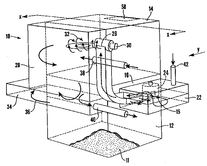
Figure 01811396

A device for thermally removing coatings and/or drying coated and/or contaminated materials comprises a support and an oven (10) pivotally connected to the support. The oven has a feeding portion (12) for accommodating the material to be treated and a turning portion (14). A heat treatment chamber (16) is arranged in the turning portion, through which hot gas (15) passes. The oven can be movably rotated between a first position in which the turning portion is higher than the feeding portion and a second position in which the feeding portion is higher than the turning portion. The device enables the oven to repeatedly move between the first and second positions, so that the material in the oven falls from one part to another and passes through the hot air flow in the heat treatment chamber. A method for using the device is also disclosed.

Figure 01811396

Description

The hot removal apparatus and the method for coating and/or impurity
Technical field
The present invention relates to from material, remove device and a kind of method of coating and/or impurity with hot method.The present invention especially relates to a kind of device and a kind of method that is suitable for the material of batch processing material is removed with hot method coating and/or impurity.
Background technology
Reclaim at present as aluminium, the demand of manganese and other metal and nonmetallic materials is improving.Usually these materials scribble paint, oil, and water, wax, plastics, or other volatile components (V.O.C.s), these compositions can be removed earlier before the material fusing.For the material that can handle under infusible situation in higher relatively temperature, those impurity can utilize heat-treating methods to remove usually, the coating removal technology of promptly generally knowing.This thermally de-coating is handled the material that also can be used for to before melting again and is carried out drying and/or sterilization.
Through being usually used in the preparation of drinks can, and can often scribbles paint, wax and/or other volatile components such as, aluminium.The waste material that produces when beverage can before using or preparation of drinks jar can be melted the back and reclaim, and must be removed in order to reduce any coating of metal loss or other impurity.
Certainly the thermally de-coating method is not limited only to be applied on the aluminium, can also be used to purifying or purify anyly can bearing metal or the nonmetallic materials that thermally de-coating is handled the temperature that is reached.Can also be used to manganese or manganese alloy are removed coating processing or purification such as the thermally de-coating method.
Known thermally de-coating is handled and is comprised and pending material is exposed in the hot gas coating of the required removal of oxidation and/or impurity.This process-exposed is to carry out in the environment of sealing, and wherein the temperature of hot gas and oxygen content can be controlled.Temperature requirement surpasses 300 degree is removed most of organic principle, and oxygen level requires between 6% to 10% usually.
If the temperature of hot gas and oxygen level are not controlled well carefully, this processing may be owing to peel off the burning of the volatile component that is discharged and burning voluntarily in hot method.This may cause the temperature control rising of hot gas to cause danger.
Material is pulverized before processing usually, and it is very important that all surface of the material after the pulverizing is exposed in the hot gas for removing coating effectively.Talk about if not so, the effect of this processing will be slightly weaker, especially when the beverage can of handling before using, may leave a blackspot on the material after the processing.Wish also that in addition material passes through to stir in processing, coating or impurity are removed from material by physical property ground.
Mainly contain three kinds at present and be used to carry out the system that thermally de-coating is handled, they are:
1. static baking box
In a static baking box, material overlays on the gauze, and hot gas passes the baking box circulation, and material is heated to required treatment temperature.
This device and not really abundant is not enclosed in wherein material because hot gas touches by the online material that stacks.As previously mentioned, it is very important the surface of all pending materials being exposed in the hot gas for removing coating.And handled material is not stirred here yet.
2. transmission baking box
This system uses a network transmission to bring the handled material of conveying to pass baking box.When material passed baking box, hot gas passed the material of putting on tape.The shortcoming of this method is as follows:
With on the degree of depth of institute's putting material limited this processing.Because material stacks, and causes the identical problem of being found in the static baking box that occurs in, the material in the middle of wherein overlaying does not touch hot gas.
Material is not stirred, so the coating of peeling off is not removed.
The life-span of conveyer belt is short.
Material must constantly be supplied with.
This processing method is not suitable for a small amount of or changing product.
3. Rotating oven
A big baking oven that tilts with horizontal plane, material is supplied with or is joined the baking oven from its highest end, moves to a minimum end under the gravity effect, and is drawn off in least significant end.Baking oven is that the material in the baking oven that makes of rotation is stirred, and a thermal current is provided, and when it passes baking oven material is heated.There are several problems in this method:
Material must constantly be supplied with.
This processing is not suitable for handles a small amount of or changing product.
Its continuous processing requirements air is at two ends, and material adds end and material draws off end, all will be by locking,
The desired rotation sealing of this baking oven causes its maintenance levels height.
Summary of the invention
The device that the purpose of this invention is to provide a kind of improved thermally de-coating and/or drying coated and/or contaminated materials overcomes or eliminates at least the defective of known thermally de-coating device.
Another object of the present invention provides a kind of thermally de-coating of improved suitable batch processing material and/or the device of drying coated and/or contaminated materials.
Another purpose of the present invention provides the device of a kind of improved thermally de-coating and/or drying coated and/or contaminated materials, than the less support equipment of known Technology Need.
A further object of the present invention provides the method for a kind of improved thermally de-coating and/or drying coated and/or contaminated materials, overcomes or eliminate at least the shortcoming of known method.
A further object of the invention provides a kind of method of thermally de-coating and/or drying coated and/or contaminated materials of improved suitable batch processing material.
Therefore, according to first feature of the present invention, the device of a kind of improved thermally de-coating and/or drying coated and/or the contaminated materials of providing, this device comprises:
A support;
A baking box that is contained on the support, it comprises the reinforced portion and the upset portion that hold pending material, this upset portion is furnished with a heat treatment chamber, wherein has thermal current therefrom to pass;
This baking box is higher than the primary importance of reinforced portion with respect to support is movable basically in a upset portion, and a reinforced portion is higher than between the second place of upset portion basically;
This installs in use, and its baking box is motion repeatedly between first and second positions, and the material in the baking box lands to another part from a part wherein under the effect of gravity, and passes thermal current.
According to a second aspect of the invention, the method for a kind of improved thermally de-coating and/or drying coated and/or the contaminated materials of providing, this method comprises:
A baking box is provided, it has the reinforced portion and the upset portion that hold pending material, upset portion is furnished with a heat treatment chamber, have thermal current to pass therethrough, movable primary importance and the reinforced portion that is higher than reinforced portion basically in a upset portion of this baking box is higher than between the second place of upset portion basically;
Material is placed in the baking box;
With baking box motion repeatedly between first and second positions, make material under the effect of gravity, in baking box, land to another part, and pass thermal current from a part.
Description of drawings
Several embodiments of the present invention will only describe by way of example with reference to the accompanying drawing here.
Fig. 1 is the schematic perspective view according to the baking box of device of the present invention;
Fig. 2 is that baking box among Fig. 1 is along the profile of X-X line;
Fig. 3 a-3g shows is diagrammatic series of views according to the different phase of device in the cycle of operation of the baking box of the Fig. 1 of comprising of the present invention;
Fig. 4 is the schematic diagram that is provided with the modifier of one second afterburner according to the present invention;
Fig. 5 shows is the change type of the baking box of Fig. 1 similar to Fig. 2; And
Fig. 6 is the front view along arrow Y direction of the baking box of Fig. 1, shows a kind of change type, is provided with a removable cassette part between the charging box of baking box and upset portion.
Specific embodiment
Referring to Fig. 1 to 3,10 refer to a baking box by numeral shown in the figure, constitute for being coated with and/or contaminated materials carries out the part of thermally de-coating and/or the dry device of handling.
Baking box 10 comprises the reinforced portion or a case 12 and the upset portion 14 that are used to hold pending material 11.Cooperate with upset portion to be provided with a thermal chamber 16, thermal current 15 pass it from a sidesway of baking box to opposite side.
Opposite side at baking box is a circular chamber 22, and gas is extracted into circular chamber 22 by circulating fan 24 from process chamber 16.An air mixer 26 is guided to an after-burner 28 with gas from circular chamber 22, burned device 30 heating of gas therein.The sidewall of after-burner 28 can be maybe can be lined with suitable exotic material by air cooled stainless steel sidewall.
It is all applicatory that the burner 30 of heated air can be designed to be suitable for coal gas or liquid fuel or both.In a most preferred embodiment, this burner volatile component that material from process chamber 16 strips down that also is designed to burn.These volatile components and gas 15 are discharged from process chamber 16 via circulating fan 24, mix with air at blender 26.The design of air mixer 26 is to guarantee that gas enters after-burner with spiral air flow, and is as shown in arrow 32, so just guarantees that volatile component has the longest residence time and is exposed to the high-temperature region of combustion flame.
By the burning volatile component, reduced because reach the fuel of the required supply heated air 15 of desired processing temperature, the overall thermal efficient of baking box has been improved.If produce enough volatile components, just do not need to increase in addition fuel and come heated air to reach desired temperature, therefore this processing just can have been heated voluntarily.
The burning volatile component has also improved radiation control by remove polluter from the gas of recirculation, and reduces the required extra and expensive processing of carrying out of the gas of discharging for the after-burner that will describe from behind.
Hot gas enters a pretreatment chamber 34 from after-burner 28, enters a limiting channel 36 again.Limiting channel 36 is supplied with gas the process chamber 16 of baking box opposite side from circular chamber 22.
What should be noted that is that thermal chamber 16 only extends the subregion of upset portion.(as shown in Figure 2) the last following 17a and the 17b of thermal chamber 16 are represented by dotted lines in Fig. 2.As shown in Figure 2, the following 17b of heat treated case and the base of upset portion 14 are haply on same plane, and its top 17a then extends a part above upset portion 14.Yet in alternate embodiments, heat treatment chamber can extend to the whole height or the scope of this upset portion, and the top margin 14a of its top 17a and upset portion 14 is coincided.In this was provided with, whole upset portion was exactly effective heat treatment box.36 in circular chamber 22 and passage extend on request.
The oxygen and the temperature levels of the gas in control system (in Fig. 2 with 23 indications) monitoring process chamber 16 guarantee security of system ground and move in the effective limited field that handled material is carried out thermally de-coating.Removing the general requirement of most of organic substance oxygen level when temperature is spent above 300 maintains below 16%.A jet pipe 38 of being regulated by control system provides fresh air to after-burner 28, thereby has controlled the oxygen and the temperature levels of desired gas.After-burner 28 is discharged burning gases by blast pipe 40, and the gas of being discharged stream is controlled by temperature and pressure controlled adjuster (not shown).
In circular chamber 22, also be provided with an auxiliary fresh air inlet 42.This auxiliary entrance 42 allows air enter circular chamber to mix with hot gas and make fan 24 cooling.Control system monitors the temperature of fan, the control valve gate control is by the air stream of this auxiliary entrance, the temperature of fan is remained on below the maximum running temperature that is allowed, for the gas that makes process chamber 16 keeps desired oxygen and temperature levels, this control system makes the air balance by jet pipe 38 and auxiliary entrance 42.
Baking box 10 is articulated in a support 44, and it has a base 46 and (sees Fig. 3 a).Shown in Fig. 3 b to 3f, baking box can be higher than between the primary importance of charging box 12 and the second place that charging box 12 is higher than upset portion 14 in a upset portion 14 and moves.
This device is provided with some devices, under the control of control system, automatically baking box is overturn between the primary importance and the second place.These devices can be any suitable forms, such as comprising one or more motors electronic or hydraulic pressure.If desired, these motors can be by the gear-box effect.These devices also selectively comprise one or more hydraulic pressure or Pneumatic pressure power cylinder.These devices can also comprise the combination of motor and power cylinder.
In a preferred embodiment, charging box 12 is removably installed on the baking box.Material just can add and draw off in the charging box 12 easily in the position that separates with baking box like this.Charging box 12 promptly becomes the Roasting oven structure part of the whole after being connected with baking box and baking box rotates together, enters or leaves charging box 12 and pass process chamber 16 so material just is being transmitted.This charging box 12 preferably is suitable for fork truck or other suitable equipment and charging box is transported into and transports baking box.
Charging box can be connected in upset portion by any suitable device (not shown), can connect with the one or more binding clasps that can control automatically as charging box, perhaps can connect with securing member such as bolt.Between the remainder of charging box and baking box, be provided with a seal (not shown), guarantee that the inside of baking box in use seals.
With reference now to Fig. 3 a to 3f, the running of this device is described.
Pending material joins in the charging box 12, and it is transported on the baking box by fork truck.After charging box 12 puts in place, promptly be locked to baking box, fork truck then leaves.Handling procedure starts under the control of control system then.
Gas is heated during by process chamber, and baking box then turns to the second place shown in Fig. 3 d from the primary importance shown in Fig. 3 b, and baking box is almost completely turned.
When baking box rotated, the material gravitate in the charging box 12 fell, and the thermal current that passes in the process chamber 16 is fallen in the upset portion 14.It should be noted that material passes the direction of thermal current 15 is passed process chamber perpendicular to thermal current direction.
The rotational action of baking box can shown in Fig. 3 e and 3f, be got back to primary importance until baking box conversely then.In this counter-rotating was rotated, material fell into charging box 12 from upset portion 14, and passes thermal current 15 again.The rotation of baking box between first and second positions requires after the repeated several times according to programme-control, and material has been finished processing.
This handling procedure goes through several stages or the cycle: a period of heating, hot gas and material are heated to the treatment temperature of expection during this period; A processing phase, the temperature of gas and material remains on treatment temperature during this period; And a last cooling cycle, the temperature of the material after gas and the processing is reduced to the level that this material can be drawn off safely during this period.
After handling procedure was finished, baking box was got back to primary importance, and charging box 12 is transported, and shown in Fig. 3 g, the material after handling so just can be sent to cooling, had stored or done processing that other are required.
The rotation of baking box guarantees that pending material passes air-flow in the process chamber in controlled mode.The drop action of material guarantees that also all surface of material is exposed in the gas fully, has improved and has removed coating and/or remove the efficient and the effect of polluting.
For coating on the oxidation material 11 and impurity, control system 23 will be controlled the velocity of rotation and the frequency of baking box in the temperature of controlling gas and oxygen level, also will guarantee safe and effective the processing, makes the loss of handled material drop to minimum.
A notable feature of this technology is that system can stop operating at any time.When handling the recoat material, this is very useful, it can guarantee that after-burner can not make temperature raise with non-prosecutor formula owing to produce a large amount of volatile components in gas, when device stops operating, combustible quantity in the gas reduces, process of combustion slows down, and makes temperature roll back the control level.When temperature was got back to acceptable level, device just recovered to rotate and continues treatment process.This stall function of baking box can guarantee to discharge the amount of the volatile substance that can control from treatment process.Process of combustion can also reduce to the position that charging box 12 falls by baking box being stopped at material.Can guarantee that like this material comes out to leave the hot side of upset portion in the air-flow.
Except thereby the stall function of baking box reduced the release of volatile component, in some cases, when needing to handle the recoat material, device can be provided with independently cooling system 50 of one second afterburner combustion system 49 and, as schematically shown in Figure 4.This second afterburner combustion system 49 can be positioned at the next door of the baking box 10 of rotation, and connects by a stainless steel or instlated tubular 51, delivers to second after-burner 49 by its hot gas and volatile matter 52 from process chamber 16.
In second after-burner, 49 inside, volatile matter is burnouted under the help of second burner 53, the gas of discharging from second after-burner 49 cools off the close independently cooling system 50 of second after-burner 49, after passing through cooling system 50, the gases that great majority are discharged are by an air pollution control device 55, as a pocket type or spray filtration system.Yet, the gas that part is discharged, for the inertia that do not contain fuel or oxygen, can be recycled in first after-burner 28 and/or second after-burner 49 by other pipeline 57, to help further to reduce burning.
Cooling system 50 uses non-direct cooling, as: a heat-exchange system, so that the cooling that can control to be provided, its determined temperature range can be accepted air pollution control device 55 and after-burner 28.Hot gas circulates by second after-burner 49 and cooling system 50 via second circulating fan 56.
Except the rotation of baking box, this device also is provided with some devices, and electronic/mechanical vibrator (not shown) for example makes baking box or can vibrate to the small part baking box.This vibrating device also can be controlled by control system 23.This vibration effect makes this device transmit material in the more controllable mode of meticulous quantity between charging box 12 and upset portion 14, improves the exchange between hot gas and the material.
This vibration can be used to improve the coating of material 11 and the removal of pollution.It is provided with material is vibrated with the frequency that equals or approach its character or resonant frequency.Perhaps, baking box (or the part of baking box, as charging box 12 or upset portion 14) at least can be with the frequency vibration of its character or resonant frequency.Like this, material is fully vibrated, improved frictional force and made gas penetration handle material 11.
What Fig. 5 showed is the change type of baking box 10, wherein is provided with several flow regulators 48 between charging box 12 and upset portion 14.In the present embodiment, flow regulator 48 comprises several plates along the elongation of upset portion width extension, these plates rotate between the open position and closed position shown in Figure 5, in the closed position, the plate edge is parallel to the base plate 47 of charging box 12 haply, and synchronously charging box 12 is cut off with upset portion 14.Flow regulator 48 is interconnected by an axle (not shown), and this as one man moves between the folding position all flow regulators.
Flow regulator 48 requires operation automatically by control system 23 according to program, by optionally cutting off charging box 12 and upset portion 14, provides a dynamic heating space to baking box, and is as described below.
In the period of heating, flow regulator 48 can cut out, and material is blocked in upset portion 14, by the pyroconductivity that improves material is shortened the period of heating.Because when gas transverse passes baking box, hot gas is forced through the material that blocks in process chamber 16.In addition, charging box 12 is heat insulation poor than upset portion 14 generally, cuts off charging box 12 in the period of heating heat loss is reduced.
After finishing the period of heating, flow regulator 48 is opened, and heating space increases, and material 11 can move between charging box 12 and upset portion 14 with common mode in processing phase and cooling cycle.
Flow regulator also can be used for the part closed position, such as spending positions 45.The motion of material between charging box 12 and upset portion 14 is restricted.The coating removal of the material by the plate that partially opens is handled be subjected to better control.
Plate also can selectively be closed, and material is blocked in charging box 12, and the hot gas of process chamber 16 is isolated fully.This can be used to control the automatic combustion of volatile component.
Device of the present invention is particularly suitable for handling and is roughly 2 tons of relative less material of a collection of quantity.This makes it can handle than known Rotating oven effectively or transmits the handled quantity materials with smaller of baking box, because material is batch processing, resets control system between each batch, makes this device go for handling different materials.
Device of the present invention can be made forr a short time than rotation baking oven or transmission baking box, and makes its floor space little.And also relatively simply required than existing apparatus maintenance and the maintenance of device of the present invention lacked.
Another advantage of device of the present invention is, the Rotating oven that it is known than oneself or transmit the needed support equipment of baking box and lack, and general transmission baking box need be provided with and feed conveyer belt, discharge conveyer and keep the storage hopper of continued operation.
Device recited above can have several to change form.Such as being provided with a kind of jet stirring system (not shown) stirring material in thermal chamber.This makes hot gas in the thermal chamber can contact material in the more processing, improves treatment effeciency.This system can comprise that the shower nozzle of one or more injection continuous flows or the strong jet of gaseous state comes the material in the heat of stirring process chamber.This gaseous state thing can be a fresh air, forms a part of control system, and the oxygen and the temperature levels of control baking box, this gaseous state thing also can be the parts of the gas 15 that circulates in baking box.
In order to realize further processing and control, also may on this device, be equipped with one or more instrument (not shown)s to the material in the baking box.In special embodiment shown in Figure 6, such instrument can be placed in the removable cassette part 56 that is located between charging box 12 and the upset portion 14, and this box body can hold one or more such instruments.Use removable cassette 58 that instrument can be changed rapidly and simply between each batch by this way.
The example that is provided to the instrument (not shown) type in the box body 58 comprises:
A reducing mechanism, when material when charging box falls into upset portion, material is pulverized.This reducing mechanism can be rotation cutting and grinding devices, perhaps other any known grinder.
In addition, can also be provided with the nonferrous metal separator of an electromagnetism in the box body 58, be used for from the material of handling, isolating nonferrous metal.This separator acts on by the material between upset portion and the charging box.General this separation will proceed to cooling cycle and finish, and nonferrous metal can be told from material and collect one independently in the bucket.This separator can be any known in the industry type that is fit to.
Can also be provided with an apparatus for feeding in the box body 58, be used for controlling material moving between charging box and upset portion.This apparatus for feeding comprises a flow control system, with shown in Figure 5 or other systems that are fit to are similar, is used for control releasable material from charging box 12.Use such apparatus for feeding that material can be discharged in the upset portion 14 from charging box 12 lentamente, make it processed, can control the release of volatile component like this in continuous haply mode.
Although show among the figure, can also be provided with the instrument of other processing or preparation material in the charging box 12.Such as, in charging box 12, can comprise a rotary furnace drying system, a pre-heating system, a mechanical agitation system, a mechanical purging system, a pressure system and/or a categorizing system.These systems are the technology of knowing in the industry.
System's (not shown) of a kind of auto feed and discharging can be used as replacement, replaces fork truck that charging box 12 is transported into and transports baking box.This system comprises pending material is transported to conveyer belt and loading hopper in the empty van 12 that charging box 12 is brought in the baking box and with it from being dynamically connected, so just can begins to have handled.After disposing, charging box separates with baking box automatically, and wherein content is poured over another conveyer belt system, is delivered to another road handling procedure or storage.This system can use several charging boxs 12, and in the different phase of whole technology, each baking box is furnished with different casings.
In some cases, when handling procedure finishes, preferably be provided with the independent chest or the bucket that hold the material of handling well, rather than it is refunded charging box 12.For instance, the material after this device can be used to prevent to handle is subjected to the pollution of charging box again.In these cases, can be provided with a device for discharging in upset portion 14, as a slide of controlling automatically (indicating with dotted line 58 among Fig. 1), material 11 can draw off from baking box by it.In this device, pending material is added in the charging box 12 as previously mentioned, yet, finishing at handling procedure, baking box is reversed, and door 58 is opened, and the material after the processing falls into the independently bucket of a material after only being used for handling.When this program was finished, baking box transferred back to its normal original position, and charging box 12 is removed, and the new charging box 12 that the pending material of another batch is housed is connected and puts in place.Being transported into and transporting charging box 12 can carry out automatically with mode recited above.
In another embodiment, the opposite side with respect to charging box 12 and device in upset portion can be provided with one second charging box (indicated with dotted line 12a in Fig. 6), the flow control system described in Fig. 5 can be arranged on each charging box 12 like this, between 12a and the upset portion 14.Such device can allow two charging boxs that pending material is housed respectively and be installed on the baking box, and the material in each casing is subsequently processed.Such as, first charging box 12 that pending material is housed is connected a side of upset portion 14, and its flow regulator near first case is closed material is blocked in first charging box 12.Baking box is reversed then, and the second charging box 12a that the pending material of another batch is housed is connected the opposite side of upset portion 14, and its flow regulator near second case is closed.Baking box starts then, and the material in the charging box 12a of one of them can have been handled, and opens the flow regulator near this casing, allows the material in this casing enter upset portion in the ordinary way.After first material processed finished, the position of baking box was parked in the material that allows after handling and gets back to its charging box 12a, and closes flow regulator.This processing procedure can come again for the material in another charging box 12.After the charging box on both sides was all handled, two charging boxs 12,12a can be unloaded down and change other casings that pending material is housed.This device can be used for reducing the time of loading and unloading between each batch, improve the output efficiency of material in proper order.

Claims (48)

1.一种涂层热除和/或干燥被涂和/或被污染的材料的装置,该装置包括:1. An apparatus for thermally removing and/or drying coated and/or contaminated material by coating, the apparatus comprising: 一个支架;a bracket; 一个装在支架上的烤箱,其包括一个容纳待处理的材料的加料部和一个翻转部,该翻转部配有一个热处理室,其中有热气流从中穿过;a frame-mounted oven comprising a charging section containing the material to be treated and a turning section equipped with a heat treatment chamber through which a stream of hot air passes; 该烤箱相对于支架可活动于一个翻转部基本上高于加料部的第一位置,和一个加料部基本上高于翻转部的第二位置之间;The oven is movable relative to the frame between a first position in which the reversing part is substantially higher than the feeding part, and a second position in which the feeding part is substantially higher than the reversing part; 该装置在使用中,烤箱在第一和第二位置之间反复运动,烤箱中的材料在重力的作用下,从其中的一部分向另一部分降落,并穿过热气流。In use of the apparatus, the oven is repeatedly moved between the first and second positions, and the material in the oven falls under the force of gravity from one part thereof to the other and passes through the hot air. 2.如权利要求1所述的装置,其中热处理室延伸于该翻转部的部分区域。2. The apparatus as claimed in claim 1, wherein the heat treatment chamber extends in a partial area of the inverting portion. 3.如权利要求1或2所述的装置,其中该热处理室延伸于该翻转部的整个范围。3. The device according to claim 1 or 2, wherein the heat treatment chamber extends over the entire range of the inverting portion. 4.如前述权利要求中任意一项所述的装置,其中该加料部可拆卸地连接于烤箱。4. Apparatus as claimed in any one of the preceding claims, wherein the loading portion is detachably connected to the oven. 5.如前述权利要求中任意一项所述的装置,还包括控制处理室中的温度和氧气的控制装置。5. Apparatus as claimed in any one of the preceding claims, further comprising control means for controlling the temperature and oxygen in the treatment chamber. 6.如权利要求5所述的装置,其中该控制装置还控制烤箱在第一和第二位置之间运动的速度和频率。6. Apparatus as claimed in claim 5, wherein the control means also controls the speed and frequency with which the oven is moved between the first and second positions. 7.如前述权利要求中任意一项所述的装置,其中该烤箱还包括一个第一后燃烧室,该装置使气体可以经过该第一燃烧室循环至处理室。7. Apparatus as claimed in any one of the preceding claims, wherein the oven further comprises a first post combustion chamber, the means allowing gas to be circulated through the first combustion chamber to the process chamber. 8.如权利要求7所述的装置,还包括一个适用于加热第一后燃烧室里的气体的燃烧器。8. The apparatus of claim 7, further comprising a burner adapted to heat the gas in the first post-combustion chamber. 9.如权利要求8所述的装置,其中该燃烧器可以将材料穿过处理室进行涂层去除处理之后产生于循环气体中的易挥发成分燃烧掉。9. The apparatus of claim 8, wherein the burner is operable to burn off volatile components produced in the circulating gas after the material passes through the chamber for decoating. 10.如权利要求9所述的装置,其中该循环气体是适合以螺旋气流进入后燃烧室的。10. The apparatus of claim 9, wherein the recycle gas is adapted to enter the afterburner in a helical flow. 11.如权利要求8或9所述的装置,其中该控制装置可以适用于使烤箱停止转动,以控制对易挥发成分的燃烧。11. Apparatus as claimed in claim 8 or 9, wherein the control means is adapted to stop the oven to control combustion of the volatile components. 12.如前述从属于权利要求7的权利要求中任意一项所述的装置,其中该烤箱还包括将新鲜空气引入循环气体的装置。12. Apparatus as claimed in any preceding claim when dependent on claim 7, wherein the oven further comprises means for introducing fresh air into the circulating air. 13.如前述权利要求中任意一项所述的装置,还包括流量调节装置用于可选择地将加料部与处理室隔断。13. Apparatus as claimed in any one of the preceding claims, further comprising flow regulating means for selectively isolating the feed section from the processing chamber. 14.如权利要求13所述的装置,其中该流量调节装置包括复数个板片,该板片可活动于一个让材料在加料部和翻转部之间通过的打开位置和一个不让材料在加料部和翻转部之间通过的关闭位置之间。14. The device as claimed in claim 13, wherein the flow regulating device comprises a plurality of plates, which can be moved between an open position allowing the material to pass between the feeding part and the turning part and an open position not allowing the material to pass between the feeding part and the turning part. between the closed position and the flipped part. 15.如权利要求14所述的装置,其中该板片由一个轴装置相互连接在一起,使其同步活动于打开和关闭位置。15. Apparatus as claimed in claim 14, wherein the plates are interconnected by a shaft means for synchronous movement in the open and closed positions. 16.如前述从属于权利要求5的权利要求13至15中任意一项所述的装置,其中该流量调节装置的动作是由控制装置控制的。16. Apparatus as claimed in any preceding claim from 13 to 15 when dependent on claim 5, wherein the action of the flow regulating means is controlled by control means. 17.如前述权利要求中任意一项所述的装置,其中在翻转部与第一个加料部相反的另一侧设有另一个加料部,该装置具有可选择地以及可独立将各个加料部与翻转部隔断的装置。17. The device as claimed in any one of the preceding claims, wherein another feeding part is provided on the opposite side of the turning part and the first charging part, and the device has the function of selectively and independently turning each feeding part A device isolated from the turning part. 18.如权利要求17所述的装置,其中该隔断装置包括一个位于各加料部和翻转部之间的如权利要求13至16所述的流量调节装置。18. Apparatus as claimed in claim 17, wherein the blocking means comprises a flow regulating means as claimed in claims 13 to 16 between each feeding section and inverting section. 19.如前述权利要求中任意一项所述的装置,还包括使烤箱或烤箱的部分振动的装置。19. Apparatus as claimed in any preceding claim, further comprising means for vibrating the oven or part of the oven. 20.如权利要求19所述的装置,其中该振动烤箱或烤箱的部分的装置适合于将材料在等于或接近该材料的性质或共振频率的频率进行振动。20. Apparatus as claimed in claim 19, wherein the means of vibrating the oven or part of the oven is adapted to vibrate the material at a frequency equal to or close to a property or resonant frequency of the material. 21.如权利要求19所述的装置,其中该振动烤箱或烤箱的部分的装置适合于将烤箱或烤箱的部分在等于或接近该烤箱或其部分的性质或共振频率的频率进行振动。21. Apparatus as claimed in claim 19, wherein the means for vibrating an oven or part of an oven is adapted to vibrate the oven or part of an oven at a frequency equal to or close to a property or resonant frequency of the oven or part thereof. 22.如前述权利要求中任意一项所述的装置,其中在加料部与翻转部之间设有一个粉碎装置用于粉碎在烤箱中待处理的材料。22. Apparatus as claimed in any one of the preceding claims, wherein between the feeding section and the turning section there is provided a comminuting device for comminuting the material to be processed in the oven. 23.如前述权利要求中任意一项所述的装置,其中在加料部与翻转部之间设有一个装置,用于从正在处理中材料中分离出非铁金属。23. Apparatus as claimed in any one of the preceding claims, wherein between the feeding section and the turning section there is provided means for separating non-ferrous metals from the material being processed. 24.如前述权利要求中任意一项所述的装置,其中在加料部与翻转部之间设有一个给进装置,用于控制待处理的材料在加料部与翻转部之间的运动。24. Apparatus as claimed in any one of the preceding claims, wherein a feed device is provided between the feeding section and the turning section for controlling the movement of the material to be treated between the feeding section and the turning section. 25.如前述权利要求中任意一项所述的装置,其中在加料部与翻转部之间可以设置一个可拆卸的盒体部,该可拆卸的盒体可以适合放置一个或多个处理或控制材料的工具,当材料在加料部与翻转部之间穿过时。25. The device according to any one of the preceding claims, wherein a detachable box body can be arranged between the feeding part and the turning part, and the detachable box body can be adapted to place one or more processing or control Tooling for material as it passes between the feeding section and the turning section. 26.如权利要求25所述的装置,其中该盒体适合放置一个如权利要求22所述的粉碎装置,和/或一个如权利要求23所述的一个非铁金属的分离装置,和/或一个如权利要求24所述的给进装置。26. The device as claimed in claim 25, wherein the box is suitable for placing a crushing device as claimed in claim 22, and/or a non-ferrous metal separating device as claimed in claim 23, and/or A feeding device as claimed in claim 24. 27.如前述权利要求中任意一项所述的装置,还包括一个或多个气体喷管,用于发射气流或气态物质的强射流,来搅拌热处理室中的材料。27. Apparatus as claimed in any one of the preceding claims, further comprising one or more gas lances for emitting a gas stream or a strong jet of gaseous material to agitate the material in the thermal treatment chamber. 28.如前述从属权利要求4的权利要求4至27中任意一项所述的装置,还包括一个自动加料和卸料系统的装置,具有一个装置用于将装有待处理的材料的加料箱传送并连接至烤箱,并用于将该加料箱从烤箱卸下来并将卸下来的加料箱从靠近烤箱的位置移开。28. Apparatus as claimed in any one of claims 4 to 27 when dependent on claim 4, further comprising means for an automatic feeding and unloading system, having a means for conveying the feeding box containing the material to be processed connected to the oven and used to remove the hopper from the oven and to move the removed hopper out of proximity to the oven. 29.如前述权利要求中任意一项所述的装置,还包括卸料装置,比如一个门,其位于翻转部中,使处理好的材料可以通过它从烤箱卸出去。29. Apparatus as claimed in any one of the preceding claims, further comprising discharge means, such as a door, located in the inversion through which processed material can be discharged from the oven. 30.如前述权利要求中任意一项所述的装置,其中该加料部包括另外的处理材料的工具,比如:一种用于旋转烘干材料的装置,和/或一种预热材料的装置,和/或一种机械搅拌材料的装置,和/或一种清洗材料的装置,和/或对材料施压的装置,和/或对材料进行分类的装置。30. Apparatus as claimed in any one of the preceding claims, wherein the feeding section comprises additional means for processing material, such as: a device for spin drying material, and/or a device for preheating material , and/or a device for mechanically agitating the material, and/or a device for cleaning the material, and/or a device for applying pressure to the material, and/or a device for classifying the material. 31.如从属于权利要求7的权利要求7至28中任意一项所述的装置,还包括一个第二后燃烧室和一个冷却装置,该设置为部分循环气体在返回第一后燃烧室之前,可以通过该第二后燃烧室和冷却装置。31. Apparatus as claimed in any one of claims 7 to 28 when appended to claim 7, further comprising a second afterburner and a cooling means arranged such that part of the recirculated gas is returned to the first afterburner before returning to the first afterburner , can pass through the second afterburner and cooling device. 32.一种涂层热除和/或干燥被涂和/或被污染的材料的装置,大致上参考并如附图1至3所示在上面描述的,或如图1至3所示如图4所修改的,或如图1至3所示如图5所修改的,或如图1至3所示如图6所修改的。32. Apparatus for thermally removing and/or drying coated and/or contaminated material substantially as hereinbefore described with reference to and as shown in the accompanying drawings 1 to 3, or as shown in FIGS. 1 to 3 Modified in FIG. 4 , or modified in FIG. 5 as shown in FIGS. 1 to 3 , or modified in FIG. 6 as shown in FIGS. 1 to 3 . 33.一种涂层热除和/或干燥被涂和/或被污染的材料的方法,包括:33. A method of thermally removing and/or drying coated and/or contaminated material comprising: 提供一个烤箱,其具有一个容纳待处理的材料的加料部和一个翻转部,翻转部配有一个加热处理室,其中有热气流从中穿过,该烤箱可活动于一个翻转部基本上高于加料部的第一位置和一个加料部基本上高于翻转部的第二位置之间;An oven is provided having a charging section containing material to be treated and a turning section equipped with a heated treatment chamber through which a hot air flow passes, the oven being movable above the charging section substantially above the charging section between a first position of the feeding section and a second position wherein the feeding section is substantially higher than the turning section; 将材料放在烤箱中;put the material in the oven; 将烤箱在第一和第二位置之间反复运动,使材料在重力的作用下,在烤箱中从一部分向另一部分降落,并穿过热气流。The oven is repeatedly moved between the first and second positions to cause the material to fall under the force of gravity from one part of the oven to the other and through the thermal air. 34.如权利要求33所述的方法,还包括:34. The method of claim 33, further comprising: 提供一个后燃烧室,使空气循环经过该后燃烧室通到处理室中。An afterburner is provided through which air is circulated to the process chamber. 35.如权利要求34所述的方法,还包括:35. The method of claim 34, further comprising: 在后燃烧室中用一个燃烧器加热气体,该燃烧器适合将材料通过处理室时进行去除涂层处理而在循环气体中产生的易挥发成分燃烧。The gas is heated in the post-combustion chamber by a burner suitable for combusting volatile components produced in the circulating gas as a result of the decoating process of the material passing through the chamber. 36.如权利要求35所述的方法,还包括:36. The method of claim 35, further comprising: 将烤箱的动作停止来控制在后燃烧室中的易挥发成分的燃烧。The operation of the oven is stopped to control the combustion of volatile components in the afterburner. 37.如权利要求33至36中的任一项所述的方法,还包括:37. The method of any one of claims 33 to 36, further comprising: 提供流量调节装置,能够被打开和关闭可选择地将加料部与翻转部隔断。A flow regulator is provided which can be opened and closed to selectively isolate the feed section from the inversion section. 38.如权利要求37所述的方法,还包括:38. The method of claim 37, further comprising: 打开和关闭该流量调节装置,使烤箱内的空间发生变化。Opening and closing the flow regulating device changes the space in the oven. 39.如权利要求37的方法,还包括:39. The method of claim 37, further comprising: 打开和关闭该流量调节装置,控制材料在加料部与翻转部之间的运动。Open and close the flow regulating device to control the movement of the material between the feeding part and the turning part. 40.如权利要求33至39中的任一项所述的方法,还包括:40. The method of any one of claims 33 to 39, further comprising: 使烤箱或烤箱的部分振动。Vibrate the oven or part of the oven. 41.如权利要求40的方法,还包括:41. The method of claim 40, further comprising: 使烤箱或烤箱的部分振动,使在烤箱中处理的材料以等于或接近其性质或共振频率的频率振动。To vibrate an oven or part of an oven so that the material being processed in the oven vibrates at or near its natural or resonant frequency. 42.如权利要求40的方法,还包括:42. The method of claim 40, further comprising: 使烤箱或烤箱的部分以等于或接近烤箱或其部分的性质或共振频率的频率振动。To vibrate an oven or part of an oven at a frequency equal to or close to the property or resonant frequency of the oven or part thereof. 43.如权利要求33至42中的任一项所述的方法,还包括:43. The method of any one of claims 33 to 42, further comprising: 在烤箱的加料部与翻转部之间提供一种粉碎装置,以及providing a pulverizing device between the charging section and the turning section of the oven, and 当材料通过时,对它进行粉碎,至少是在材料从加料部进入翻转部的运动初始时。The material is comminuted as it passes, at least initially during the movement of the material from the feeding section into the turning section. 44.如权利要求33至43中的任一项所述的方法,还包括:44. The method of any one of claims 33 to 43, further comprising: 在加料部与翻转部之间提供一种非铁金属分离装置,以及providing a non-ferrous metal separating device between the feeding part and the turning part, and 在处理的冷却阶段中,当材料通过翻转部和加料部时,从处理的其余材料中分离出非铁金属。During the cooling phase of the process, non-ferrous metals are separated from the remainder of the process as the material passes through the inverting and feeding sections. 45.如权利要求33至44中的任一项所述的方法,还包括:45. The method of any one of claims 33 to 44, further comprising: 在加料部与翻转部之间提供一种给进装置,以及providing a feeding device between the feeding part and the turning part, and 使用给进装置控制材料在加料部与翻转部之间的运动。Use the feeding device to control the movement of the material between the feeding section and the turning section. 46.如权利要求33至45中的任一项所述的方法,还包括:46. The method of any one of claims 33 to 45, further comprising: 通过将材料置于从一个或多个喷管中发射的气态物质中来搅拌热处理室中的材料。The material in the thermal processing chamber is agitated by placing the material in a gaseous mass emitted from one or more nozzles. 47.如权利要求33至46中的任一项所述的方法,还包括:47. The method of any one of claims 33 to 46, further comprising: 在翻转部提供一种卸料装置,通过该装置材料可以从烤箱中卸出;以及providing a discharge device at the inverting section through which material can be discharged from the oven; and 在处理程序完成后,通过该卸料装置从烤箱中卸出材料。After the processing procedure is completed, the material is discharged from the oven through this discharge device. 48.一种涂层热除和/或干燥被涂和/或被污染的材料的方法,大致上参考并如附图所示在上面所描述的。48. A method of coating thermally removing and/or drying coated and/or contaminated material substantially as hereinbefore described with reference to and as shown in the accompanying drawings.
CNB018113966A 2000-06-19 2001-06-19 Device and method for thermally removing coatings and/or impurities Expired - Fee Related CN1178802C (en)

Applications Claiming Priority (2)

Application Number Priority Date Filing Date Title
GBGB0014800.7A GB0014800D0 (en) 2000-06-19 2000-06-19 Batch operatating de-coating apparatus
GB0014800.7 2000-06-19

Publications (2)

Publication Number Publication Date
CN1437534A true CN1437534A (en) 2003-08-20
CN1178802C CN1178802C (en) 2004-12-08

Family

ID=9893828

Family Applications (1)

Application Number Title Priority Date Filing Date
CNB018113966A Expired - Fee Related CN1178802C (en) 2000-06-19 2001-06-19 Device and method for thermally removing coatings and/or impurities

Country Status (16)

Country Link
US (2) US7331119B2 (en)
EP (1) EP1292457B1 (en)
JP (1) JP4866530B2 (en)
CN (1) CN1178802C (en)
AT (1) ATE314209T1 (en)
AU (1) AU2001274260A1 (en)
CA (1) CA2413372C (en)
CY (1) CY1105281T1 (en)
DE (1) DE60116299T2 (en)
DK (1) DK1292457T3 (en)
ES (1) ES2256249T3 (en)
GB (1) GB0014800D0 (en)
PT (1) PT1292457E (en)
RU (1) RU2268151C2 (en)
SK (1) SK286559B6 (en)
WO (1) WO2001098092A1 (en)

Cited By (4)

* Cited by examiner, † Cited by third party
Publication number Priority date Publication date Assignee Title
CN101175580B (en) * 2005-03-24 2010-11-17 奥弗奈尔·亨利·帕瑞 Apparatus and method for thermal removal of coatings and/or impurities
CN102834532A (en) * 2010-02-11 2012-12-19 勒法特·埃尔·查勒比 Metal recovery from contaminated metal scrap
CN102945015A (en) * 2012-12-06 2013-02-27 北京埃夫信环保科技有限公司 Automatic control system of intelligent paint stripping furnace
CN109939984A (en) * 2019-03-19 2019-06-28 柴瑞贤 A kind of Oil Paint Slag recycling equipment

Families Citing this family (15)

* Cited by examiner, † Cited by third party
Publication number Priority date Publication date Assignee Title
GB0014800D0 (en) * 2000-06-19 2000-08-09 Perry Ophneil H Batch operatating de-coating apparatus
DE60317789T2 (en) * 2002-06-17 2008-10-30 Maskinfabrikken Fornax A/S DEVICE AND METHOD FOR THE THERMAL CLEANING AND SEPARATION OF METAL PARTS
GB0506033D0 (en) * 2005-03-24 2005-04-27 Perry Ophneil H Apparatus and method for thermally removing coatings and/or impurities
GB0230082D0 (en) * 2002-12-24 2003-01-29 Perry Ophneil H Oven
JP3919798B2 (en) * 2005-06-28 2007-05-30 シャープ株式会社 Washing and drying machine
US7662206B2 (en) 2005-09-15 2010-02-16 Vitag Corporation Organic containing sludge to fertilizer alkaline conversion process
DE102006008100B8 (en) * 2006-02-20 2009-02-12 Ijzerlo Holding B.V. Process for drying goods in a fluidized bed dryer and fluidized bed dryer
US9695092B2 (en) 2006-02-23 2017-07-04 Anuvia Plant Nutrients Corporation Process for treating sludge and manufacturing bioorganically-augmented high nitrogen-containing inorganic fertilizer
GB0812683D0 (en) * 2008-07-11 2008-08-20 Chalabi Rifat A Multi-heat zone gasifier
IT1392061B1 (en) * 2008-10-10 2012-02-09 Whirlpool Co OPENING OVEN FOR AIR INTAKE IN ITS CAVITY
GB0915557D0 (en) * 2009-09-07 2009-10-07 Chalabi Rifat A Apparatus for processeng waste material
DE102009041789A1 (en) * 2009-09-18 2011-03-31 Klaus Riegert Process for recycling aluminum from beverage cans
WO2011082301A2 (en) 2009-12-30 2011-07-07 Vitag Holdings, Llc Bioorganically-augmented high value fertilizer
GB2502115B (en) 2012-05-15 2015-04-01 Chinook End Stage Recycling Ltd Improvements in waste processing
CN102995340B (en) * 2012-10-18 2014-05-07 吴江市元通纺织品有限公司 Residual coating cleaner

Family Cites Families (12)

* Cited by examiner, † Cited by third party
Publication number Priority date Publication date Assignee Title
US2290036A (en) 1940-11-14 1942-07-14 Udylite Corp Machine for treating articles in bulk
US3171638A (en) * 1960-05-05 1965-03-02 Kennecott Copper Corp Rotary furnace production of sponge iron
US3483363A (en) * 1966-04-22 1969-12-09 Leeds & Northrup Co Method and apparatus for maximizing the output of a rotary kiln
JPS5023153Y1 (en) * 1970-03-16 1975-07-12
US3619908A (en) * 1970-04-03 1971-11-16 Klefstad Engineering Co Inc Device for cleaning and drying metal chips
JPH01147280A (en) * 1987-12-03 1989-06-08 Nippon Kansoki Kk Revolution type ventilation drier
JPH0615171B2 (en) * 1988-03-24 1994-03-02 松爾 中込 Drying device for raw materials of plastic powder
US5059116A (en) * 1988-12-16 1991-10-22 Gillespie & Powers, Inc. Apparatus and process for removing volatile coatings from scrap metal
US4941822A (en) * 1989-07-20 1990-07-17 Marvin Evans Apparatus for heat treating contaminated particulate material
SU1722897A1 (en) * 1989-12-27 1992-03-30 П.А.Борбатенко, Л.Ф.Борисова и И.П.Селедцова Surface-cleaning device
GB0014800D0 (en) * 2000-06-19 2000-08-09 Perry Ophneil H Batch operatating de-coating apparatus
US6601315B2 (en) * 2000-12-14 2003-08-05 Bausch & Lomb Incorporated Combined fluidized bed dryer and absorption bed

Cited By (5)

* Cited by examiner, † Cited by third party
Publication number Priority date Publication date Assignee Title
CN101175580B (en) * 2005-03-24 2010-11-17 奥弗奈尔·亨利·帕瑞 Apparatus and method for thermal removal of coatings and/or impurities
CN102834532A (en) * 2010-02-11 2012-12-19 勒法特·埃尔·查勒比 Metal recovery from contaminated metal scrap
CN102945015A (en) * 2012-12-06 2013-02-27 北京埃夫信环保科技有限公司 Automatic control system of intelligent paint stripping furnace
CN102945015B (en) * 2012-12-06 2016-08-03 北京埃夫信环保科技有限公司 Intelligent paint stripping furnace automatic control system
CN109939984A (en) * 2019-03-19 2019-06-28 柴瑞贤 A kind of Oil Paint Slag recycling equipment

Also Published As

Publication number Publication date
CY1105281T1 (en) 2010-03-03
JP2003536046A (en) 2003-12-02
CA2413372C (en) 2011-09-13
ES2256249T3 (en) 2006-07-16
US20080120867A1 (en) 2008-05-29
GB0014800D0 (en) 2000-08-09
SK286559B6 (en) 2008-12-05
SK92003A3 (en) 2003-09-11
US20030145482A1 (en) 2003-08-07
WO2001098092A1 (en) 2001-12-27
PT1292457E (en) 2006-05-31
JP4866530B2 (en) 2012-02-01
RU2268151C2 (en) 2006-01-20
US8096063B2 (en) 2012-01-17
AU2001274260A1 (en) 2002-01-02
EP1292457B1 (en) 2005-12-28
DE60116299D1 (en) 2006-02-02
ATE314209T1 (en) 2006-01-15
CN1178802C (en) 2004-12-08
DK1292457T3 (en) 2006-05-15
EP1292457A1 (en) 2003-03-19
US7331119B2 (en) 2008-02-19
CA2413372A1 (en) 2001-12-27
DE60116299T2 (en) 2006-08-31

Similar Documents

Publication Publication Date Title
CN1437534A (en) Apparatus and method for thermal removal of coatings and/or impurities
US8231382B2 (en) Apparatus and method for thermally removing coatings and/or impurities
US7207797B2 (en) Oven for the treatment of contaminated materials
EP1871547B1 (en) Apparatus and method for thermally removing coatings and/or impurities
HK1107541A1 (en) Apparatus and method for thermally removing coatings and/or impurities
HK1107541B (en) Apparatus and method for thermally removing coatings and/or impurities
JP2005207679A (en) Batch-type rotary oil heat treatment equipment
JPH09227957A (en) Steel recycling method from used steel beverage cans

Legal Events

Date Code Title Description
C06 Publication
PB01 Publication
C10 Entry into substantive examination
SE01 Entry into force of request for substantive examination
C14 Grant of patent or utility model
GR01 Patent grant
TR01 Transfer of patent right

Effective date of registration: 20170920

Address after: British Nottinghamshire

Patentee after: Chinook Technology Co.,Ltd.

Address before: New jersey, USA

Patentee before: Chinook technology LLC

Effective date of registration: 20170920

Address after: New jersey, USA

Patentee after: Chinook technology LLC

Address before: Fog city, New Jersey, USA

Patentee before: Rafat Archarleby

Effective date of registration: 20170920

Address after: Fog city, New Jersey, USA

Patentee after: Rafat Archarleby

Address before: British Nottingham

Co-patentee before: Rafat Archarleby

Patentee before: Ophneil Henry Perry

CF01 Termination of patent right due to non-payment of annual fee

Granted publication date: 20041208

Termination date: 20190619