CN1448751A - Portable optical device - Google Patents
Portable optical device Download PDFInfo
- Publication number
- CN1448751A CN1448751A CN03109154A CN03109154A CN1448751A CN 1448751 A CN1448751 A CN 1448751A CN 03109154 A CN03109154 A CN 03109154A CN 03109154 A CN03109154 A CN 03109154A CN 1448751 A CN1448751 A CN 1448751A
- Authority
- CN
- China
- Prior art keywords
- circuit board
- control circuit
- mount plate
- system mount
- telescope
- Prior art date
- Legal status (The legal status is an assumption and is not a legal conclusion. Google has not performed a legal analysis and makes no representation as to the accuracy of the status listed.)
- Pending
Links
Images


Classifications
-
- G—PHYSICS
- G02—OPTICS
- G02B—OPTICAL ELEMENTS, SYSTEMS OR APPARATUS
- G02B27/00—Optical systems or apparatus not provided for by any of the groups G02B1/00 - G02B26/00, G02B30/00
-
- G—PHYSICS
- G02—OPTICS
- G02B—OPTICAL ELEMENTS, SYSTEMS OR APPARATUS
- G02B23/00—Telescopes, e.g. binoculars; Periscopes; Instruments for viewing the inside of hollow bodies; Viewfinders; Optical aiming or sighting devices
- G02B23/16—Housings; Caps; Mountings; Supports, e.g. with counterweight
Landscapes
- Physics & Mathematics (AREA)
- General Physics & Mathematics (AREA)
- Optics & Photonics (AREA)
- Astronomy & Astrophysics (AREA)
- Telescopes (AREA)
- Studio Devices (AREA)
Abstract
一种便携光学装置,包括光系统安装片,控制电路板和一个内框。内框有第一支撑柱以及第二支撑柱。第一支撑柱是用来支撑光系统安装片的。第二支撑柱是用来支撑控制电路板的。第一和第二支撑柱这样构建是为了让光系统安装片位于内框和控制电路板中间。
A portable optical device includes an optical system installation sheet, a control circuit board and an inner frame. The inner frame has a first support column and a second support column. The first support column is used to support the optical system installation sheet. The second support column is used to support the control circuit board. The first and second support columns are constructed in such a way that the optical system mounting piece is located between the inner frame and the control circuit board.
Description
技术领域technical field
本发明涉及具有控制电路板的便携光学装置。The present invention relates to a portable optical device with a control circuit board.
背景技术Background technique
作为便携光学装置的一个例子,这里有数码相机,视频相机,单目镜和具有自动调焦机构的双目镜,每个装置都有一个固态成像器件。As an example of portable optical devices, there are digital still cameras, video cameras, monoculars, and binoculars with autofocus mechanisms, each of which has a solid-state imaging device.
在光学装置内有一个内框,一个电子电路板和其他各种元件或单元。元件或单元(另一个元件或单元附着其上)附着或固定在内框上。这样,复杂的元件或单元安置引起安装错误,其结果是不仅元件或单元的安置准确度降低,同时整体结构的强度也降低了。Inside the optical unit there is an inner frame, an electronic circuit board and various other components or units. A component or unit (to which another component or unit is attached) is attached or fixed to the inner frame. Thus, complicated component or unit placement causes installation errors, with the result that not only the accuracy of component or unit placement is lowered, but also the strength of the overall structure is lowered.
为什么一个元件或单元必须附着在另个元件或单元上的原因是为了降低位置误差的影响。具有相对较大体积的元件如用于照相系统的光系统安装片或者一个控制电路板,一般是附着到内框上。如果大体积元件的附着位置有误差,这些误差将被传递到连接到大体积元件和单元以及内框上的其他元件和单元。这样,就很难或不可能将其他元件或器件与内框对准或直接附着在其上The reason why one component or unit must be attached to another is to reduce the effect of positional errors. Components with a relatively large volume, such as an optical system mounting sheet for a camera system or a control circuit board, are generally attached to the inner frame. If there are errors in the attachment positions of the bulky components, these errors will be transferred to other components and units attached to the bulky components and units and to the inner frame. This makes it difficult or impossible to align or attach other components or devices directly to the inner frame
特别地,对滑动型双目望远镜,其壳体可通过滑移来调节瞳孔间距,既然其上装有望远镜光系统的光系统安装片具有两个可相对移动的滑板,光系统安装片的结构是复杂的。因此,对于直接附着尽可能多的元件或单元到内框的情形,光系统安装片装到内框上的安装位置必须和控制电路板的安装位置综合起来考虑。In particular, for sliding binoculars, the housing can be slid to adjust the interpupillary distance. Since the optical system mounting sheet on which the telescope optical system is mounted has two relatively movable slide plates, the structure of the optical system mounting sheet is complicated. Therefore, for the situation of directly attaching as many components or units as possible to the inner frame, the installation position of the optical system mounting piece on the inner frame must be considered comprehensively with the installation position of the control circuit board.
发明内容Contents of the invention
因此,本发明的一个目的是提供一种光学装置,其中,光系统安装片和控制电路板附着到内框上的位置得以改善以便于使得尽可能多的元件或单元可直接地附着到内框上。Therefore, an object of the present invention is to provide an optical device in which the attachment positions of the optical system mounting sheet and the control circuit board to the inner frame are improved so that as many components or units as possible can be directly attached to the inner frame superior.
依据本发明,这里提供了一种便携光学装置,其包括一个光系统安装片,一个控制电路板和一个内框。该内框具有用来支撑光系统安装片的第一支撑机构,,和用于支撑控制电路板的第二支撑机构,第一和第二支撑机构的构建方式是光系统安装片位于内框和控制电路板中间。According to the present invention, a portable optical device is provided, which includes an optical system mounting plate, a control circuit board and an inner frame. The inner frame has a first supporting mechanism for supporting the optical system mounting sheet, and a second supporting mechanism for supporting the control circuit board, the construction of the first and second supporting mechanisms is that the optical system mounting sheet is located between the inner frame and the second supporting mechanism. In the middle of the control circuit board.
第一支撑机构具有一个在内框上形成并在光系统安装片和控制电路板的厚度方向上延伸的第一支撑柱,第二支撑机构有在内框上形成并在光系统安装片和控制电路板厚度方向延伸的第二支撑柱。在此情况下,第一支撑柱上形成有第一螺纹孔,光系统安装片上形成有第一插入孔(与第一螺纹孔对应),第二螺纹孔是在第二支撑柱的末端部分形成的,该末端支撑着控制电路板,相对于光系统安装片,控制电路板位于内框的对面,控制电路板形成有对应于第二螺纹孔的第二插入孔,,第一螺栓插进第一插入孔并拧进第一螺纹孔中,第二螺栓插到第二插入孔并拧进第二螺纹孔中,使得光系统安装片和控制电路板都能连接到内框上并彼此平行。The first support mechanism has a first support column formed on the inner frame and extending in the thickness direction of the optical system installation sheet and the control circuit board, and the second support mechanism has a first support column formed on the inner frame and extended between the optical system installation sheet and the control circuit board. A second support column extending in the thickness direction of the circuit board. In this case, a first threaded hole is formed on the first support column, a first insertion hole (corresponding to the first threaded hole) is formed on the optical system mounting sheet, and a second threaded hole is formed on the end portion of the second support column. Yes, the end supports the control circuit board, relative to the optical system mounting sheet, the control circuit board is located on the opposite side of the inner frame, the control circuit board is formed with a second insertion hole corresponding to the second threaded hole, and the first bolt is inserted into the second threaded hole. One is inserted into the hole and screwed into the first threaded hole, and the second bolt is inserted into the second insertion hole and screwed into the second threaded hole, so that the optical system mounting piece and the control circuit board can be connected to the inner frame and parallel to each other.
优选地,内框具有一个中心部分,一个从中心沿光系统安装片延伸的翼部以及一个从翼部外缘延伸的垂直壁,以使垂直壁基本上与翼部垂直,第一支撑柱从中心部分延伸,至少一个第二支撑柱从中心部分延伸,其它第二支撑柱从垂直壁延伸。Preferably, the inner frame has a central portion, a wing extending from the center along the optical system mounting plate and a vertical wall extending from the outer edge of the wing, so that the vertical wall is substantially perpendicular to the wing, and the first support column extends from A central portion extends from which at least one second support column extends and other second support columns extend from the vertical wall.
第二支撑柱可处于光系统安装片的外侧。至少一个第二支撑柱可穿过光系统安装片。The second support column can be located on the outside of the optical system installation sheet. At least one second support column may pass through the optical system mounting sheet.
可选地,便携光学装置还包括一对安装在光系统安装片上的望远镜光系统,以便于器件具有双目镜的功能。Optionally, the portable optical device further includes a pair of telescope optical systems installed on the optical system mounting sheet, so that the device has the function of binoculars.
在此情形下,优选地,光系统安装片由两片状元件组成,一个望远镜光系统安装在其中之一上,而另外一个望远镜光系统安放在另外一个上。两个片状元件能够相对移动以便于望远镜光系统的光轴之间的距离可以调节。另外,每个望远镜光系统中的元件都可以和每个望远镜光系统中的其他元件做相对移动,这就使得望远镜光系统具备聚焦功能。In this case, preferably, the optical system mounting sheet is composed of two sheet-shaped elements, one of which is mounted with the telescope optical system, and the other of which is mounted with the other. The two plate elements can move relative to each other so that the distance between the optical axes of the telescope optical system can be adjusted. In addition, the components in each telescope optical system can move relative to other components in each telescope optical system, which makes the telescope optical system have a focusing function.
便携光学装置可进一步包括一个由内框旋转支撑的旋转轮,和一个移动转换机构,此转换机构将旋转轮的旋转运动转化为望远镜光系统对中的元件的聚焦动作,转换机构位于旋转轮和望远镜光系统元件的中间位置。The portable optical device may further include a rotating wheel rotatably supported by the inner frame, and a translation conversion mechanism, which converts the rotational movement of the rotating wheel into a focusing action of the elements centered by the telescope optical system, and the conversion mechanism is located between the rotating wheel and The middle position of the optical system components of the telescope.
旋转轮可由一个旋转轮圆筒构成,其中盛有一个照相光系统。The rotating wheel may consist of a rotating wheel cylinder containing a photographic light system.
照相光系统可以安放在透镜筒里,它位于旋转轮圆筒当中。移动转换机构位于旋转轮圆筒和透镜筒之间,移动转换机构将旋转轮圆筒的旋转运动转化为透镜筒的聚焦运动,以聚焦照相光系统。The photographic light system can be housed in the lens barrel, which is located in the rotating wheel cylinder. The movement conversion mechanism is located between the rotating wheel cylinder and the lens barrel, and the movement conversion mechanism converts the rotation motion of the rotation wheel cylinder into the focusing movement of the lens barrel to focus the photographic light system.
可选地,中心部分装有近乎U型的凹槽,其内装有管状部件和透镜筒,,该管状部件由旋转轮圆筒组成。Optionally, the central part is fitted with an almost U-shaped groove, inside which is housed a tubular part consisting of a rotating wheel cylinder.
附图说明Description of drawings
参照附图,从下面的描述中可以更好地理解本发明的目标和优点。Objects and advantages of the present invention may be better understood from the following description, taken with reference to the accompanying drawings.
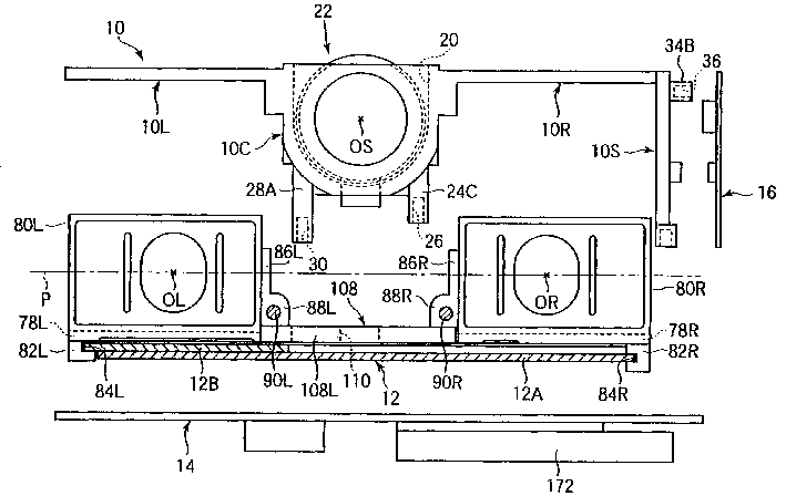
图1是本发明一个实施例的纵向剖视图,示出了此具有照相功能的双目望远镜中,光柱安装片、控制电路板和一个电源电路板还没有装配到内框里的状态;图2示出的是将光柱安装片,控制电路板和电源电路板装配到内框里的状态的纵向剖视图;Fig. 1 is a longitudinal sectional view of an embodiment of the present invention, has shown in this binocular telescope with photographic function, the state that light column installation piece, control circuit board and a power supply circuit board have not been assembled in the inner frame; Fig. 2 shows Shown is a longitudinal sectional view of the state where the light column mounting sheet, the control circuit board and the power circuit board are assembled into the inner frame;
图3是内框的平面视图;Fig. 3 is the plane view of inner frame;
图4是内框的底视图;Fig. 4 is the bottom view of inner frame;
图5是光系统安装片的平面视图;Fig. 5 is a plan view of the optical system mounting sheet;
图6是安装在光系统安装片上的望远镜光系统对的平面视图;Fig. 6 is a plan view of the telescope optical system pair installed on the optical system mounting sheet;
图7是安装片的一个平面视图,其上放有垂直三棱镜系统和目镜系统,该两系统装在望远镜光系统对中。Figure 7 is a plan view of the mounting plate on which the vertical prism system and eyepiece system are placed, the two systems being centered in the optical system of the telescope.
图8是图7沿线VIII-VIII观察的纵向剖视图;Fig. 8 is a longitudinal sectional view viewed along line VIII-VIII of Fig. 7;
图9是图2沿线XI-XI观察的纵向剖视图;以及Fig. 9 is a longitudinal sectional view viewed along line XI-XI of Fig. 2; and
图10显示的是一个环状部件和螺纹面啮合在一起的前视图,螺纹面是在旋转轮圆筒外表面上形成的。Figure 10 shows a front view of an annular member engaged with the threaded surface formed on the outer surface of the rotating wheel cylinder.
具体实施方式Detailed ways
参照附图中所示的实施例来描述本发明。注意到,在本实施例中便携光学装置是具有照相功能的双筒望远镜。The invention is described with reference to the embodiments shown in the drawings. Note that in this embodiment the portable optical device is binoculars with a camera function.
参照图1和2,双筒望远镜有一个内框10,其中光系统安装片12,控制电路板14和电源电路板16都直接地附着在其上。Referring to Figures 1 and 2, the binoculars have an
在双筒望远镜的装配过程中,光系统安装片12,控制电路板14,电源电路板16以及其他元件或单元(例如管状元件22)都附着在内框10上,然后将整个装配结构放在双筒望远镜的壳体18里。在图2中,壳体18的横截面由双点划线指示。也就是说,壳体18是盒子状的。During the assembly process of the binoculars, the optical
壳体18包括主壳体18A和可移动壳体18B。可移动壳体18B同主壳体18A以滑动方式啮合使得可移动壳体18B能够相对于主壳体18A移动。亦即,可移动壳体18B在收缩位置和最大伸展位置之间移动,收缩位置如图2中所示,最大伸展位置是可移动壳体从收缩位置拉出到的位置。The
壳体18A和18B的滑动表面都作用有适当的摩擦力,这样当想将可移动壳体18B从主壳体18A处拉伸或收缩到主壳体18A处之前,必须对可移动壳18B施加一定的压力或拉力。这样,由于在壳体18A和18B的滑动面有适当的摩擦力存在,使可移动壳体18B处于完全收缩(图2)和最大拉伸位置之间的光位置保持静止或固定是可能的。Both the sliding surfaces of
图3显示的是内框10的平面视图,图4是内框10的底视图。FIG. 3 shows a plan view of the
内框10有中心区10C,从中心区10C向右延伸的右翼区10R和一个从右翼区10R右侧缘向下(亦即,朝向内框10的底部方向)延伸的垂直壁10S,以及一个从中心区10C向左侧延伸的左翼10L。右翼区10R和左翼区10L整体和中心区10C连接在一起。垂直壁10S与右翼区10R整体连接到一起并与之呈垂直关系。内框10是由适当材料如轻质铝合金和硬合成树脂组成的。从图1,2和3中可看出,中心区10C有一个近似呈U型的凹槽20,在此凹槽20中装有管状部件22。The
如图4中所示,在中心区10C底面整体形成四个支柱24A,24B,24C和24D。并且在光系统安装片12和控制电路板14的厚度方向或向下以相同长度延伸,如图1所示。在支撑柱24A,24B,24C和24D的每个末端上形成螺纹孔26。支撑柱24A,24B沿中心区10C的纵向排列,同样,24C和24D沿纵向排列。支撑柱24A,24B,24C和24D用来支撑或悬挂光系统安装片12。As shown in FIG. 4, four
另外,两支撑柱28A和28B整体形成于中心区10C的底面并以相同的长度向下或者沿光系统安装片12和控制电路板14的厚度方向延伸。支撑柱28A和28B与支撑柱24A和24B相邻放置,并沿中心区10C的纵向排列。同支撑柱24A和24B相比,支撑柱28A和28B更靠近内框外侧缘一些。支撑柱28A和28B要比支撑柱24A和24B长而且处于光安装片12的外侧。这样当内框10,光系统安装片12以及控制电路板14按如图2所示装配时,支撑柱28A和28B的末端部分与控制电路板14靠在一起,相对于光安装片12而言,控制电路板14位于内框的对面。In addition, two
另外,支撑柱28C和28D整体形成于垂直壁10S的底沿并以相同长度向下延伸。支撑柱28C和28D的端面处于由支撑柱28A和28B端面决定的平面内。这样,将内框10,光系统安装片12以及控制电路板14照如图2所示装配时,支撑柱28C和28D的末端部分与控制电路板14靠在一起。In addition,
在每个支撑柱28A,28B,28C和28D的端头处形成螺纹孔30。与28A,28B,28C和28D对应,在控制电路板14区域上形成四个螺纹插孔。如图2所示,螺栓32插入到螺纹插孔中并拧进螺纹孔30中,控制电路板14由内框10悬挂或者支撑着,光系统安装片12和控制电路板14相互平行地分别连接到右翼10R和左翼10L上。A threaded hole 30 is formed at the end of each support post 28A, 28B, 28C and 28D. Corresponding to 28A, 28B, 28C and 28D, four threaded sockets are formed on the
注意到,如果光系统安装片12如图5中所示的虚线方向延伸,支撑柱28B通过孔39穿过光系统安装片12。基于这个原因,管状部件22可以牢固稳定地连接到光系统安装片12上。Note that if the optical
参照图1到4可看出,短杆34A和34B整体形成在内框10的垂直壁10S上,并从垂直壁10S的上部边沿端部以相同长度延伸。短杆34A和34B在中心区10C的纵向方向上排列,他们是用来支撑电源电路板16的。亦即,在每个短杆34A和34B的端面形成一个螺纹孔36,相对应于短杆34A和34B,在电源电路板16区域形成螺纹插孔。如图2中所示,螺栓38插进螺纹插孔当中并拧进螺纹孔36中,电源电路板16与垂直壁10S的侧面附着在一起。1 to 4, the
如图5所示,光系统安装片12是由方形板12A和滑动装在方形板上的滑板12B构成的。滑板12B有一个几乎和方形板12A具有相同宽度的方形区域12B’和一个延伸区域12B”,12B”整体连接到方形区域12B’并从方形区域12B’向右延伸(图5)。在方形板12A上形成四个螺纹插孔40,并与支撑柱24A,24B,24C和24D位置对应地布置。亦即,如图2所示,螺栓42被插进孔40中并拧进螺纹孔26中,光系统安装片12通过支撑柱24A,24B,24C和24D由中心区10C所悬挂或支撑。As shown in FIG. 5, the optical
方形板12A固定到主壳体部分18A,为了固定它,从方形板12A的上部外侧延伸出一凸起部分44(图5),通过弯曲之将在突起部分44上形成垂直片46。在图5里,垂直片46以截面视图标示,而且在垂直片46上形成两个孔48A和48B。另外,从方形板12A的底部外侧延伸出另一凸起部分50(图5),通过弯曲之将在突起部分50形成垂直片52。在图5里,垂直片52以截面视图标示,而且在垂直片52上形成一个孔54。The
这样,螺栓(未示出)被插进垂直片46和52上的孔48A和54中并拧进主壳体部分18A中,使得方形片12A固定到主壳体部分18A上。注意到,垂直片46的另一个孔48B,用于将在后面描述的另一个目的。Thus, bolts (not shown) are inserted into
滑板12B固定到可移动壳体18B上,为达此目的,从滑板12B的方形区12B’的左上角(图5)延伸一个突起部分56,通过弯曲他,能够在突起部分56上形成一个垂直片58。在图5中,垂直片58以截面视图标示,而且在垂直片58形成有孔60。另外,从滑板12B的方形区12B’的上部外侧(图5)延伸出一个突起部分62,通过弯曲他,能够在突起部分62上形成一个垂直片64。在图5中,垂直片64以截面视图标示,而且在垂直片64上形成有孔66A和66B。The
这样,螺栓(未示出)被插进垂直片58和64上的孔60和66A中,并拧进移动壳体部分18B中,使得滑板12B能固定到可移动壳体18B上。注意到,垂直片64的其他孔66B用于将在后面描述的另一个目的。Thus, bolts (not shown) are inserted into
在滑板12B的方形区域12B’中形成两个导槽68A,在延伸区域12B”中形成另一个导槽68A。三个导槽68A相互平行,并以相同长度在左右方向上延伸(图5)。固定在方形板12A上的导销68B通过滑动方式与导槽68A啮合。每个导槽68A的长度与可移动壳体部分18B相对于主壳体部分18A的可移动距离相对应,亦即,可移动壳体18B处于收缩位置(图2)和处于最大拉伸位置之间的距离。这样,当可移动壳体部分18B相对于主壳体部分18A左右移动时,滑板12B也对方形板12A做相对移动。Two
如图6所示,光系统安装片12A是用来安装望远镜系统对70R和70L的,70R和70L具有对称结构并形成双筒望远镜。望远镜光系统70R是为操作者右眼使用的右望远镜系统。望远镜光系统70R安装在方形板12A上面,包含一个物镜棱镜系统72R,一个垂直三棱镜系统74R和一个目镜系统76R。望远镜光系统70L是为操作者左眼使用的左望远镜系统,望远镜光系统70L安装在滑板12B的方形区域12B’上面,包含一个物镜棱镜系统72L,一个垂直三棱镜系统74L和一个目镜系统76L。从上面的描述中可知,当可移动壳体部分18B相对于主壳体部分18A移动时,滑板12B也相对于方形板12A做相对移动,以使望远镜光系统70R和70L对的光轴之间的距离,亦即,瞳孔间距得以调节。As shown in FIG. 6, an optical
注意到,为解释简单起见,在下面的描述中,前后各自定义为,相对于望远镜光系统对70R和70L的物镜棱镜系统一侧和目镜棱镜系统一侧。Note that, for simplicity of explanation, in the following description, front and rear are respectively defined as the objective prism system side and the eyepiece prism system side with respect to the telescope
右边的望远镜光系统70R的物镜棱镜系统72R固定在方形板12A上面,而垂直三棱镜系统74R和目镜棱镜系统76R可以相对于物镜棱镜系统72R做前后移动,使得可以聚焦右望远镜光系统70R。类似地,左边的望远镜光系统70L的物镜棱镜系统72R固定在滑板12B上的方形区域12B’上面,而垂直三棱镜系统74L和目镜棱镜系统76L可以相对于物镜棱镜系统72L做前后移动,使得可以聚焦左望远镜光系统70L。The objective
如图7中所指示的右安装板78R和左安装板78L是用来聚焦上面描述的望远镜光系统对70R和70L的。如图6所示,右安装板78R位于方形板12A上并可以前后移动,右望远镜光系统70R的垂直三棱镜系统74R安装在右安装板78R上面。如图7和8所示,沿右安装板78R后侧装有一个垂直板80R。如图6中所示,右目镜棱镜系统76R附着在垂直板80R上面。Right mounting
类似地,左安装板78L位于滑板12B上并可以前后移动,进而,如图6所示,左望远镜光系统70L的垂直三棱镜系统74L安装在左安装板78L上面。如图6和7所示,沿左安装板78L后侧装有一个垂直板80L。,左目镜棱镜系统76L附着在垂直板80L上面。Similarly, the
如图7和8所示,右安装板78R上装有一个导块82R,固定在其右侧附近并位于其下方。导块82R中形成有槽84R,如图1和2所示,他是以滑动方式来承载方形板12A的右侧沿的。同样,右安装板78R上沿左侧沿并在其上有一个侧壁86R,侧壁86R的下半部分形成一个膨胀区域88R,其上面有个过孔用来以滑动方式承载导杆90R。As shown in Figures 7 and 8, the
如图6中所示,导杆90R在方形板12A的前后方向上来回移动,其前端牢固地被方形板12A支撑着。即,在导杆90R的前端形成一个内螺纹孔,螺栓92R(图6)被插进垂直片46上的孔48(图5),并拧进内螺纹孔中,使得导杆90R的前端能够固定到方形板12A上。As shown in FIG. 6, the
导杆90R的后端被方形板12A以上面描述的类似方式牢固地支撑着。即,如图5所示,从方形板12A的后端延伸出突出物94,通过弯曲之形成垂直片96。在图5里,垂直片96以截面视图标示,而且在垂直片96上面形成一个孔98,是为了与垂直片44上的孔48B对齐。在导杆90R的后端形成一个内螺纹孔,而螺栓100R(图6)被插进垂直片96上的孔98里面并拧进内螺纹孔中,以便于导杆90R的后端固定到方形板12A。The rear end of the
这样,右安装板78R能够沿导杆90R做前后移动,以便于可以改变从垂直三棱镜系统74R和目镜棱镜系统76R到物镜棱镜系统72R之间的距离,因此右望远镜光系统70R可以聚焦。Like this, the
同样,如图7和8所示,左安装板78L有一个导块82L,固定到其左侧沿附近并位于其下方。导块82中形成有槽84L,如图1和2所示,他是以滑动方式来承载滑板12B的左侧沿的。同样,左安装板78L沿右侧沿并在其上有一个侧壁86L,侧壁86L的下半部分形成一个膨胀区域88L,其上面有个过孔用来以滑动方式承载导杆90L。Also, as shown in FIGS. 7 and 8, the
如图6中所示,导杆90L在滑板12B的前后方向上来回移动,其前端牢固地被滑板12B上的方形区域12B’支撑着。即,在导杆90L的前端形成一个内螺纹孔,螺栓92L(图6)被插进垂直片62上的孔66B(图5)中,并拧进内螺纹孔中,使得导杆90L的前端能够固定到方形区域12B’上。As shown in FIG. 6, the
导杆90L的后部被滑板12B的方形区域12B’以上面描述的类似方式牢固地支撑着。即,如图5所示,从方形区域12B’的后端延伸出突出物102,通过弯曲之形成垂直片104。在图5里,垂直片104以截面视图标示,而且在垂直片104上面形成一个孔106,是为了与垂直片62上的孔66B对齐。在导杆90L的后端形成有一个内螺纹孔,而螺栓100L(图6)被插进垂直片104上的孔106里面并拧进内螺纹孔中,以便于导杆90L的后端固定到方形区域12B’上。The rear portion of
这样,左安装板78L能够沿导杆90L做前后移动,以便于可以改变从垂直三棱镜系统74L和目镜棱镜系统76L到物镜棱镜系统72L之间的距离,因此左望远镜光系统70L可以聚焦。Like this, left mounting
为了能够沿导杆90R和90L同时移动左右安装片78R和78L以便于左右安装片78R和78L之间的距离可变,左右安装片78R和78L通过一个可伸展的耦合器108将他们连接在一起。In order to be able to move the left and right mounting
具体来说,如图6和7所示,可伸展耦合器108包括一个方形块状部件108R和一个叉状部件108L,后者以滑动方式承载块状部件108R。块状部件108R牢固地附着在侧壁86R前端的膨胀区域88R的底侧。块状部件108L牢固地附着在侧壁86L前端的膨胀区域88L的底侧。108R和108L两个部件的长度都大于可移动壳体部分18B从收缩位置(图2)到最大拉伸位置之间的距离。亦即,即使可移动壳体部分18B从收缩位置(图2)扩展到最大拉伸位置,108R和108L之间还要保持滑动啮合状态。Specifically, as shown in FIGS. 6 and 7, the
这样,即使是可移动壳体部分18B相对于主壳体部分18A处于任意拉伸位置,安装板78R和78L沿导杆90R和90L所做的同时转换移动可随时得到保证。Thus, simultaneous translational movement of mounting
如上面所描述的,在内框10的中心区10C形成一个近似U型的凹槽20,管状部件放在凹槽20当中。如图9所示,管状部件22有旋转轮圆筒112和透镜筒114,后者同轴地放置在旋转轮圆筒112中。如后面将要描述的,在凹槽20里旋转轮圆筒112是以可旋转方式获得支撑的,而且在透镜筒114保持静止以确保不沿中心轴转动的同时,透镜筒114可沿中心轴移动。As described above, an approximately
在旋转轮圆筒112上有个旋转轮116。旋转轮116在旋转轮圆筒112的外侧面形成了一个环状突出物118,而且环状橡皮盖120附着在环状突出物118上。螺纹面122在旋转轮圆筒112的外侧面形成。环状部件124是拧的方式固定到螺纹面122上的。即,如图10中所示,和旋转轮圆筒112上的螺纹面122啮合在一起的三个突出物126,形成于环状部件124的内壁,并被等间隔放置。On the
另外,如图10所示,在环状部件124的外侧形成一个扁平面128,舌状物130从环状部件124中突出出来。扁平面128和舌状物130被分别放在环状物124的相对侧。如图4所示,在内框10的中心区10C的底部形成一个方形开口132。当管状部件22放置在凹槽20中时,环状部件124的舌状物130穿过开口132。In addition, as shown in FIG. 10 , a
在双筒望远镜的装配过程中,当管状物22放在中心区10C的凹槽20时,凹槽20部分地被弯片134盖住,弯片134被弄弯是为了配合旋转轮圆筒112的外侧面,旋转轮116和螺纹面122都有一部分裸露出来。即,弯片134上有两个方形开口136和138,目的是旋转轮116部分从方形开口136露出,螺纹面122部分从方形开口138露出。During assembly of the binoculars, when the
这样,当环状部件22放进中心区10C的凹槽20,而且凹槽20被弯片134覆盖时,如图9所示,定位环状部件124的位置使得扁平面128从方形孔138中露出,旋转轮圆筒112在凹槽20内转动。注意到,用螺栓等(未示出)将弯片134固定在中心区10C中。In this way, when the ring-shaped
如上面所述,在装配过程中,光系统安装片12,控制电路板14,电源电路板16和其他元件或单元都装配到内框10中,以使得这种装配结构能够放进双筒望远镜的壳体18里。在这种条件下,虽然旋转轮116部分通过开口138露出,方形开口部分地被主壳体部分18A的顶壁18A’所覆盖,而且扁平面128以滑动方式和顶壁18A’内壁啮合。因而,当使用者用,比如手指接触旋转轮116的裸露部分来转动旋转轮116时,由于与螺纹面122以螺纹方式接触,环状部件124就沿着旋转轮圆筒112的中心轴移动。由于扁平面128和顶壁18A’啮合在一起,环状部件124不能转动。移动方向决定于旋转轮圆筒112的旋转方向。As mentioned above, in the assembly process, the optical
如图9中所示,照相光系统140安装在透镜筒114中,且有第一棱镜组142和第二棱镜组144。在透镜筒114的前端部分形成有键槽146和148。每个键槽(146和148)沿照相光系统140的光轴方向从透镜筒114的前沿以预定长度进行延伸。在U型凹槽20的前端部分的底部形成一个盲孔150。销152插进盲孔150当中,并和键槽146啮合在一起。在弯片134的前端部分形成有过孔154。销156插进过孔154中,并键槽146啮合在一起。这样,透镜筒114不能沿中心轴旋转,但可以沿中心轴移动,移动的距离与键槽对146和148的长度相对应。As shown in FIG. 9 , a photographing
中心区10C的尖端是一个接头158,它与透镜筒114同轴。亦即,接头158的中心轴和透镜筒114中的照相光系统140的光轴一致。并作为照相光系统140的光入口。At the tip of the
在中心区10C的后端160处形成一个环状阶梯开口162。在透镜筒114中照相光系统140的光轴和环状阶梯开口62的中心轴是一致的。成像器件孔容器164安装在环状阶梯开口162中,并与照相光系统140在一条直线上。映像器件孔容器164盛有由固态成像元件组成的组件,固态成像元件如CCD166和控制CCD166工作的CCD电路板168。另外,成像器件孔容器164有一个光学低通滤波器170,他被放置在距CCD166光接收表面预定距离处。这样,本实施例的双筒望远镜具有与数码相机相同的照相功能,以使由照相光系统140获得的物象通过光低通滤波器170在CCD166的光接收表面上形成。An annular stepped
在图1和2中,照相光系统的光轴由参考序号OS标示,而左右望远镜光系统70L和70R的光轴由参考序号OL和OR标示。OR和OL的光轴是互相平行的,并和照相光系统140的光轴OS平行。如图2所示,光轴OR和OL决定一个平面P,P与照相光系统140的光轴OS平行。左右望远镜光系统70R和70L可以相对于P做平行移动,使得光轴OR和OL之间的距离,亦即瞳孔间距可以调节。In FIGS. 1 and 2, the optical axis of the photographic optical system is indicated by reference numeral OS, and the optical axes of the left and right telescopic
当安装内框10和光系统安装片12时,将环状部件124的舌状物130的尖端部分放置到块状部件108R上形成的开口110里,如图9所示。因此,如上面所描述,当旋转轮圆筒112通过旋转轮116旋转时,环状部件124将沿着旋转轮圆筒112的中心轴移动。左安装片78L和右安装片78R整体地随着环状部件124移动。即,由于旋转轮116的旋转,目镜棱镜系统76L,76R与物镜棱镜系统72R,72L之间的距离得以调节,以使望远镜光系统70R和70L对聚焦。When installing the
在本实施例中,望远镜光系统70R和70L对的设计方法是,例如,当任一物镜棱镜系统72R和72L到任一目镜棱镜系统76R和76L之间的距离最短时,望远镜光系统对70R和70L对位于双筒望远镜前40米到无穷远处的物体进行对焦;当观察位于双筒望远镜前2米到40米之间的物体时,为了在物体上聚焦,目镜棱镜系统要和物镜棱镜系统分开。换句话说,当目镜棱镜系统76R和76L离开物镜棱镜系统72R和72L最大距离时,望远镜光系统对70R和70L能够聚焦位于双筒望远镜前约2米处的物体。In the present embodiment, the pair of telescope
这样,在双筒望远镜中,在内框10的一侧提装将旋转轮圆筒112的旋转运动转换为望远镜光系统70R和70L对的聚焦运动的转换机构,以及在光系统安装片12的一侧装有另一个移动转换机构。当光系统安装片12连接到内框10时,这些部分啮合在一起以便于移动转换机构发挥作用。In this way, in the binoculars, a conversion mechanism that converts the rotational motion of the
当照相光系统140构造成能进行全焦照相时,其中,照相光系统140能够聚焦位于双筒望远镜前预定距离的近物体,以及位于无穷远处的物体。而且只是使用全焦照相术进行照相操作,不需要在透镜筒114上安装调焦机构。然而在本实施例中,因为双筒望远镜需要对位于双筒望远镜前小于2米的近物体成像(这类似普通相机),透镜筒114上需要安装聚焦机构。When the photographing
因此,内螺纹面形成于旋转轮圆筒112的内壁上,而和旋转轮圆筒112上内螺纹面啮合的外螺纹面则形成于透镜筒114的外壁。当旋转轮圆筒112旋转时,透镜筒114沿照相光系统140的光轴移动,由于键槽146和148与销152和156啮合,透镜筒114不能旋转。旋转轮圆筒112的旋转方向决定透镜筒114的移动方向。这样,形成于旋转轮圆筒112的内壁以及透镜筒114的外壁的螺纹面构成移动转换机构,这种机构将旋转轮圆筒112的转动转化为透镜筒114的线性移动或聚焦动作。Therefore, the internal thread surface is formed on the inner wall of the
在旋转轮圆筒112的外壁上形成的螺纹面和在其内壁构成的螺纹面在相反方向上互相斜靠,这样当旋转轮圆筒112以目镜棱镜系统76R和76L同物镜棱镜系统72R和72L分离方式旋转时,透镜筒114就偏离CCD166。由于这个原因,近物体映像能够在CCD166的光接收表面聚焦。依据望远镜光系统对70R和70L以及照相光系统140的光特性,螺纹面122的螺距和内壁螺纹面螺距是各自不同的。The threaded surface formed on the outer wall of the
如图1和2所示,CF卡容器172附着在控制电路板14的下表面。通过主壳体部分18A底部形成的开口(未示出),CF卡或存储器卡可拆卸地装入CF卡容器172中。由CCD166获得的映像数据存储在CF卡存储器172中。注意到,各种各样的电子元件包括处理器,存储器,半导体,晶体管等等都安装在控制电路板14的上下面(在图1和2中未示出)。As shown in FIGS. 1 and 2 , a
另一方面,各种各样的电子元件安装在电源电路板16上,其结果如大家所知,电源电路板的重量较重。这样,大重量作用于主壳体部分18A的外侧,这使得双筒望远镜不便于拿。因此,在本实施例中,可移动壳体部分18B外部的内空间用做电池室,以使整个双筒望远镜的重量平衡得以改善。On the other hand, various electronic components are mounted on the power supply circuit board 16, and as a result, the power supply circuit board is heavy as is known. Thus, a large weight acts on the outside of the
在本实施例中,照相光系统140被放置在旋转轮圆筒112中,以使具有照相功能的双筒望远镜可以组装得很紧凑。然而,照相光系统140不必放在旋转轮圆筒112里面,在此情形下,旋转轮圆筒112可以是一个细长实心杆。In this embodiment, the camera
如上面描述的,在光学装置当中,具有相对较大体积的元件,亦即光系统安装片,控制电路板以及电源电路板被放置在内框和光系统安装板中间。因此,在需要的情况下,其他元件或单元可以直接地附着在内框上。例如,在上面描述的实施例中,与望远镜光系统瞳孔间距调节以及聚焦控制相关的元件,以及不必附着在光系统安装片在的元件可以附着在内框上,而不对控制电路板产生影响。这样,附着到内框上的元件或单元的附着准确性是基于内框的,以改善附着准确性。进一步地,由于很多的元件或单元在内框中是作为一个整体来装配的。器件的整体结构得以加强。As described above, in the optical device, components with relatively large volume, namely, the optical system mounting sheet, the control circuit board and the power supply circuit board are placed between the inner frame and the optical system mounting board. Therefore, other elements or units can be directly attached to the inner frame if necessary. For example, in the above-described embodiments, components related to interpupillary distance adjustment and focus control of the telescope optical system, and components that do not need to be attached to the optical system mounting plate can be attached to the inner frame without affecting the control circuit board. In this way, the attachment accuracy of the components or units attached to the inner frame is based on the inner frame to improve the attachment accuracy. Further, since many elements or units are assembled as a whole in the inner frame. The overall structure of the device is enhanced.
虽然这里参照附图描述了本发明实施例,显然在不偏离本发明范围的情况下,本领域的普通技术人员可以做许多的变形和改型的。Although the embodiments of the present invention have been described herein with reference to the accompanying drawings, it is apparent that many variations and modifications may be made by those skilled in the art without departing from the scope of the present invention.
Claims (13)
Applications Claiming Priority (2)
| Application Number | Priority Date | Filing Date | Title |
|---|---|---|---|
| JP2002102396A JP2003298912A (en) | 2002-04-04 | 2002-04-04 | Portable optical device having electronic control circuit board |
| JP2002102396 | 2002-04-04 |
Publications (1)
| Publication Number | Publication Date |
|---|---|
| CN1448751A true CN1448751A (en) | 2003-10-15 |
Family
ID=19193702
Family Applications (1)
| Application Number | Title | Priority Date | Filing Date |
|---|---|---|---|
| CN03109154A Pending CN1448751A (en) | 2002-04-04 | 2003-04-03 | Portable optical device |
Country Status (7)
| Country | Link |
|---|---|
| US (1) | US20030189752A1 (en) |
| JP (1) | JP2003298912A (en) |
| KR (1) | KR20030079765A (en) |
| CN (1) | CN1448751A (en) |
| DE (1) | DE10315488A1 (en) |
| GB (1) | GB2387238B (en) |
| TW (1) | TW200404168A (en) |
Families Citing this family (2)
| Publication number | Priority date | Publication date | Assignee | Title |
|---|---|---|---|---|
| KR100695075B1 (en) * | 2005-07-01 | 2007-03-14 | 삼성전자주식회사 | Dual lens assembly and imaging device having same |
| AT522469B1 (en) * | 2019-07-19 | 2020-11-15 | Swarovski Optik Kg | Long-range optical device and focusing device |
Family Cites Families (16)
| Publication number | Priority date | Publication date | Assignee | Title |
|---|---|---|---|---|
| US4067027A (en) * | 1976-08-31 | 1978-01-03 | Asia American Industries Ltd. | Binocular telescope containing a camera |
| USD259569S (en) * | 1978-05-30 | 1981-06-16 | J. Gerber and Co., (Japan) Ltd. | Combined camera and binoculars |
| USD262632S (en) * | 1979-02-27 | 1982-01-12 | Ajia Amerikan Boueki Kabushiki Kaisha | Combined binoculars and detachable camera |
| USD265479S (en) * | 1979-05-23 | 1982-07-20 | Ajia Amerikan Boueki Kabushiki Kaisha | Combined binocular and detachable camera |
| US5187646A (en) * | 1989-09-13 | 1993-02-16 | Mannesmann Kienzle Gmbh | Data storage device with an arrangement for receiving a transportable, card-shaped or disk-shaped data storage unit so that the data storage unit is inaccessible in an operating position |
| US5107404A (en) * | 1989-09-14 | 1992-04-21 | Astec International Ltd. | Circuit board assembly for a cellular telephone system or the like |
| DE4244161A1 (en) * | 1991-12-26 | 1993-07-01 | Asahi Optical Co Ltd | Automatic focus field glasses - have lens which can be moved in direction of optical axis for sharp adjustment and lenses movable along optical axis for varying refractory force |
| IL106269A (en) * | 1992-09-30 | 1996-05-14 | Int Standard Electric Corp | Consumer night vision viewing apparatus |
| US6088053A (en) * | 1996-07-15 | 2000-07-11 | Hammack; Jack C. | Digital record and replay binoculars |
| US5930035A (en) * | 1996-08-20 | 1999-07-27 | Asahi Kogaku Kogyo Kabushiki Kaisha | Binocular with a movable unit including an erecting system and an eyepiece system |
| US6206728B1 (en) * | 1999-02-22 | 2001-03-27 | Molex Incorporated | Shielded electrical connector system |
| JP2001281555A (en) * | 2000-03-31 | 2001-10-10 | Nikon Corp | Binoculars with imaging function |
| JP2001320181A (en) * | 2000-05-09 | 2001-11-16 | Sony Computer Entertainment Inc | Electronic appliance |
| JP2002151866A (en) * | 2000-11-14 | 2002-05-24 | Nec Corp | Strengthened mounting structure of portable apparatus |
| TW594046B (en) * | 2001-09-28 | 2004-06-21 | Pentax Corp | Optical viewer instrument with photographing function |
| TW584218U (en) * | 2002-06-06 | 2004-04-11 | Hon Hai Prec Ind Co Ltd | Mounting device for heat sink |
-
2002
- 2002-04-04 JP JP2002102396A patent/JP2003298912A/en not_active Withdrawn
-
2003
- 2003-03-25 TW TW092106688A patent/TW200404168A/en unknown
- 2003-03-28 US US10/400,807 patent/US20030189752A1/en not_active Abandoned
- 2003-04-02 KR KR10-2003-0020827A patent/KR20030079765A/en not_active Withdrawn
- 2003-04-03 CN CN03109154A patent/CN1448751A/en active Pending
- 2003-04-04 DE DE10315488A patent/DE10315488A1/en not_active Withdrawn
- 2003-04-04 GB GB0307848A patent/GB2387238B/en not_active Expired - Fee Related
Also Published As
| Publication number | Publication date |
|---|---|
| KR20030079765A (en) | 2003-10-10 |
| GB0307848D0 (en) | 2003-05-14 |
| GB2387238B (en) | 2005-07-13 |
| DE10315488A1 (en) | 2003-10-23 |
| JP2003298912A (en) | 2003-10-17 |
| GB2387238A (en) | 2003-10-08 |
| TW200404168A (en) | 2004-03-16 |
| US20030189752A1 (en) | 2003-10-09 |
Similar Documents
| Publication | Publication Date | Title |
|---|---|---|
| CN1439929A (en) | Retractable lens system and method of retracting the retractable lens system | |
| CN1682525A (en) | Image sensor module | |
| CN1279385C (en) | Optical viewer device with camera function | |
| CN100338492C (en) | Lens barrels | |
| CN1409153A (en) | Optical viewer device with camera function | |
| CN1267762C (en) | Optical viewer device with camera function | |
| CN1284021C (en) | Assembling structure for double tube telescope with shooting function | |
| CN1782848A (en) | Imaging device having an optical image stabilizer | |
| CN1448751A (en) | Portable optical device | |
| CN201359673Y (en) | Focusing and imaging device used for camera | |
| CN100412595C (en) | Zoom lens module | |
| CN1453633A (en) | Portable apparatus | |
| JP4730500B2 (en) | Lens device | |
| CN1277138C (en) | Lens shift mechanism, camera unit, and electronic equipment | |
| CN1253742C (en) | Optical positioning regulator of optical unit | |
| CN1304869C (en) | Optical device | |
| CN100345023C (en) | Air conditioning unit | |
| CN1815345A (en) | Display amplifier device of digital camera | |
| JP6009826B2 (en) | Lens device | |
| CN1272648C (en) | Double-drum telescope | |
| CN1610382A (en) | Digital image capture device capable of capturing images from different angles | |
| CN213023717U (en) | Lens focusing device | |
| CN1768288A (en) | Lens holding device, lens-barrel, and imaging device | |
| CN2864725Y (en) | Lens mechanism with zoom and auto focus functions | |
| CN1376939A (en) | Camera adapter for microscope |
Legal Events
| Date | Code | Title | Description |
|---|---|---|---|
| C06 | Publication | ||
| PB01 | Publication | ||
| C10 | Entry into substantive examination | ||
| SE01 | Entry into force of request for substantive examination | ||
| AD01 | Patent right deemed abandoned | ||
| C20 | Patent right or utility model deemed to be abandoned or is abandoned |