CN1472425A - How two-stroke reciprocating internal combustion engines work - Google Patents
How two-stroke reciprocating internal combustion engines work Download PDFInfo
- Publication number
- CN1472425A CN1472425A CNA031471935A CN03147193A CN1472425A CN 1472425 A CN1472425 A CN 1472425A CN A031471935 A CNA031471935 A CN A031471935A CN 03147193 A CN03147193 A CN 03147193A CN 1472425 A CN1472425 A CN 1472425A
- Authority
- CN
- China
- Prior art keywords
- cylinder
- scavenging
- combustion chamber
- internal combustion
- reciprocating internal
- Prior art date
- Legal status (The legal status is an assumption and is not a legal conclusion. Google has not performed a legal analysis and makes no representation as to the accuracy of the status listed.)
- Granted
Links
Images

Classifications
-
- F—MECHANICAL ENGINEERING; LIGHTING; HEATING; WEAPONS; BLASTING
- F02—COMBUSTION ENGINES; HOT-GAS OR COMBUSTION-PRODUCT ENGINE PLANTS
- F02D—CONTROLLING COMBUSTION ENGINES
- F02D13/00—Controlling the engine output power by varying inlet or exhaust valve operating characteristics, e.g. timing
- F02D13/02—Controlling the engine output power by varying inlet or exhaust valve operating characteristics, e.g. timing during engine operation
- F02D13/028—Controlling the engine output power by varying inlet or exhaust valve operating characteristics, e.g. timing during engine operation for two-stroke engines
- F02D13/0284—Variable control of exhaust valves only
-
- F—MECHANICAL ENGINEERING; LIGHTING; HEATING; WEAPONS; BLASTING
- F02—COMBUSTION ENGINES; HOT-GAS OR COMBUSTION-PRODUCT ENGINE PLANTS
- F02B—INTERNAL-COMBUSTION PISTON ENGINES; COMBUSTION ENGINES IN GENERAL
- F02B75/00—Other engines
- F02B75/02—Engines characterised by their cycles, e.g. six-stroke
-
- F—MECHANICAL ENGINEERING; LIGHTING; HEATING; WEAPONS; BLASTING
- F02—COMBUSTION ENGINES; HOT-GAS OR COMBUSTION-PRODUCT ENGINE PLANTS
- F02B—INTERNAL-COMBUSTION PISTON ENGINES; COMBUSTION ENGINES IN GENERAL
- F02B25/00—Engines characterised by using fresh charge for scavenging cylinders
- F02B25/02—Engines characterised by using fresh charge for scavenging cylinders using unidirectional scavenging
- F02B25/04—Engines having ports both in cylinder head and in cylinder wall near bottom of piston stroke
-
- F—MECHANICAL ENGINEERING; LIGHTING; HEATING; WEAPONS; BLASTING
- F02—COMBUSTION ENGINES; HOT-GAS OR COMBUSTION-PRODUCT ENGINE PLANTS
- F02B—INTERNAL-COMBUSTION PISTON ENGINES; COMBUSTION ENGINES IN GENERAL
- F02B29/00—Engines characterised by provision for charging or scavenging not provided for in groups F02B25/00, F02B27/00 or F02B33/00 - F02B39/00; Details thereof
- F02B29/08—Modifying distribution valve timing for charging purposes
-
- F—MECHANICAL ENGINEERING; LIGHTING; HEATING; WEAPONS; BLASTING
- F02—COMBUSTION ENGINES; HOT-GAS OR COMBUSTION-PRODUCT ENGINE PLANTS
- F02B—INTERNAL-COMBUSTION PISTON ENGINES; COMBUSTION ENGINES IN GENERAL
- F02B37/00—Engines characterised by provision of pumps driven at least for part of the time by exhaust
-
- F—MECHANICAL ENGINEERING; LIGHTING; HEATING; WEAPONS; BLASTING
- F02—COMBUSTION ENGINES; HOT-GAS OR COMBUSTION-PRODUCT ENGINE PLANTS
- F02D—CONTROLLING COMBUSTION ENGINES
- F02D13/00—Controlling the engine output power by varying inlet or exhaust valve operating characteristics, e.g. timing
- F02D13/02—Controlling the engine output power by varying inlet or exhaust valve operating characteristics, e.g. timing during engine operation
- F02D13/028—Controlling the engine output power by varying inlet or exhaust valve operating characteristics, e.g. timing during engine operation for two-stroke engines
-
- F—MECHANICAL ENGINEERING; LIGHTING; HEATING; WEAPONS; BLASTING
- F02—COMBUSTION ENGINES; HOT-GAS OR COMBUSTION-PRODUCT ENGINE PLANTS
- F02B—INTERNAL-COMBUSTION PISTON ENGINES; COMBUSTION ENGINES IN GENERAL
- F02B75/00—Other engines
- F02B75/02—Engines characterised by their cycles, e.g. six-stroke
- F02B2075/022—Engines characterised by their cycles, e.g. six-stroke having less than six strokes per cycle
- F02B2075/025—Engines characterised by their cycles, e.g. six-stroke having less than six strokes per cycle two
-
- F—MECHANICAL ENGINEERING; LIGHTING; HEATING; WEAPONS; BLASTING
- F02—COMBUSTION ENGINES; HOT-GAS OR COMBUSTION-PRODUCT ENGINE PLANTS
- F02B—INTERNAL-COMBUSTION PISTON ENGINES; COMBUSTION ENGINES IN GENERAL
- F02B3/00—Engines characterised by air compression and subsequent fuel addition
- F02B3/06—Engines characterised by air compression and subsequent fuel addition with compression ignition
-
- F—MECHANICAL ENGINEERING; LIGHTING; HEATING; WEAPONS; BLASTING
- F02—COMBUSTION ENGINES; HOT-GAS OR COMBUSTION-PRODUCT ENGINE PLANTS
- F02F—CYLINDERS, PISTONS OR CASINGS, FOR COMBUSTION ENGINES; ARRANGEMENTS OF SEALINGS IN COMBUSTION ENGINES
- F02F7/00—Casings, e.g. crankcases
- F02F2007/0097—Casings, e.g. crankcases for large diesel engines
-
- Y—GENERAL TAGGING OF NEW TECHNOLOGICAL DEVELOPMENTS; GENERAL TAGGING OF CROSS-SECTIONAL TECHNOLOGIES SPANNING OVER SEVERAL SECTIONS OF THE IPC; TECHNICAL SUBJECTS COVERED BY FORMER USPC CROSS-REFERENCE ART COLLECTIONS [XRACs] AND DIGESTS
- Y02—TECHNOLOGIES OR APPLICATIONS FOR MITIGATION OR ADAPTATION AGAINST CLIMATE CHANGE
- Y02T—CLIMATE CHANGE MITIGATION TECHNOLOGIES RELATED TO TRANSPORTATION
- Y02T10/00—Road transport of goods or passengers
- Y02T10/10—Internal combustion engine [ICE] based vehicles
- Y02T10/12—Improving ICE efficiencies
Landscapes
- Engineering & Computer Science (AREA)
- Chemical & Material Sciences (AREA)
- Combustion & Propulsion (AREA)
- Mechanical Engineering (AREA)
- General Engineering & Computer Science (AREA)
- Supercharger (AREA)
- Output Control And Ontrol Of Special Type Engine (AREA)
Abstract
本发明提供了一种二冲程往复式内燃机、特别是一种大型柴油机的工作方法。二冲程往复式内燃机包括一个汽缸和一个增压器组,汽缸具有一个排气阀和一个扫气用空气开口,在汽缸中布置有一个可在一个下死点位置和一个上死点位置之间沿一个运行表面往复运动的活塞,增压器组具有一个由来自汽缸的燃烧室的废气驱动的涡轮,并具有一个压缩空气的转子,将压缩空气作为扫气用空气通过一个扫气用空气开口供给汽缸的燃烧室,排气阀在进行燃料喷射并随后燃烧之后和在扫气用空气随后进入汽缸的燃烧室之前在一个预扫气相位中在低于至少一个预先设定的转速限值时先打开、然后再关闭。本发明还涉及根据上述方法工作的往复式内燃机。
The invention provides a working method of a two-stroke reciprocating internal combustion engine, in particular a large diesel engine. A two-stroke reciprocating internal combustion engine comprises a cylinder with an exhaust valve and an air opening for scavenging, and a cylinder arranged between a bottom dead center position and a top dead center position, and a supercharger group. A piston reciprocating along a running surface, the supercharger group has a turbine driven by exhaust gases from the combustion chambers of the cylinders and has a rotor that compresses air as scavenging air through a scavenging air opening supply to the combustion chamber of the cylinder, the exhaust valve in a pre-scavenging phase below at least one predetermined rotational speed limit after fuel injection and subsequent combustion and before the subsequent entry of scavenging air into the combustion chamber of the cylinder Turn it on first, then turn it off. The invention also relates to a reciprocating internal combustion engine operating according to the method described above.
Description
技术领域technical field
本发明涉及一种二冲程往复式内燃机、特别是一种大型柴油机的工作方法,和涉及一种根据该方法工作的二冲程往复式内燃机、特别是一种大型柴油机。The invention relates to a working method of a two-stroke reciprocating internal combustion engine, especially a large diesel engine, and a two-stroke reciprocating internal combustion engine working according to the method, especially a large diesel engine.
背景技术Background technique
为了增加往复式内燃机、例如用于船舶的或产生电能用的固定发电厂的二冲程大型柴油机的动力,在一个燃烧循环之后新鲜空气通过一个通常设计为一个废气涡轮增压器的增压器组,利用在该燃烧循环之后离开汽缸的燃烧室的废气的热能中的一部分,在增加的压力下被引入汽缸的燃烧室。为此目的,热废气通过打开一个排气阀从汽缸的燃烧室供给增压器组。该增压器组大体由一个涡轮构成,该涡轮由在压力下进入增压器组的热废气驱动。该涡轮然后驱动一个转子,从而新鲜空气被吸入并压缩。一个扩散器、一个带有一个水分分离器的空气冷却器和一个进气接收器放置在该带有一个作为压缩机的转子的涡轮的下游,这样的布置形式通常称为涡轮增压器。从这里,被压缩的新鲜空气,也称为增压空气或扫气用空气,最终被输送入大型柴油机的各个汽缸中。根据大型柴油机的类型,空气的供入在汽缸的不同位置进行。例如对于带有纵向扫气的二冲程发动机而言,空气通过布置在汽缸的下部区域的运行表面中的扫气槽而引入汽缸的燃烧室。对于四冲程发动机而言,该增压空气通常通过一个或多个布置在汽缸盖中的进气阀而引入汽缸的燃烧室,二冲程发动机在汽缸盖中装配有进气阀,以取代在汽缸的下部区域中的扫气槽,也是公知的。To increase the power of reciprocating internal combustion engines, such as two-stroke large diesel engines for ships or stationary power plants for generating electrical energy, after a combustion cycle the fresh air is passed through a supercharger group, usually designed as an exhaust gas turbocharger , utilizing a portion of the thermal energy of the exhaust gases leaving the combustion chamber of the cylinder after this combustion cycle, being introduced under increased pressure into the combustion chamber of the cylinder. For this purpose, hot exhaust gas is fed from the combustion chamber of the cylinder to the supercharger group by opening an exhaust valve. The supercharger group generally consists of a turbine driven by hot exhaust gases entering the supercharger group under pressure. The turbine then drives a rotor whereby fresh air is sucked in and compressed. A diffuser, an air cooler with a moisture separator and an intake receiver are placed downstream of the turbine with a rotor acting as a compressor, an arrangement commonly referred to as a turbocharger. From here, the compressed fresh air, also known as charge air or scavenging air, is finally fed into the individual cylinders of the large diesel engine. Depending on the type of large diesel engine, the air supply takes place at different points in the cylinder. For example, in the case of two-stroke engines with longitudinal scavenging, air is introduced into the combustion chamber of the cylinder via scavenging grooves arranged in the running surface in the lower region of the cylinder. For a four-stroke engine, this pressurized air is usually introduced into the combustion chamber of the cylinder through one or more intake valves arranged in the cylinder head, and a two-stroke engine is equipped with an intake valve in the cylinder head A scavenging groove in the lower region of the is also known.
由于增压器组的涡轮只由从汽缸的燃烧室中逸出的热废气驱动,所以已知的增压器组只能以较低的效率工作,特别是在刚启动之后不久或是在低于发动机的某个转速限值时,更是如此。因此,增压器组经常附带有一个或多个附加的机械的或电的辅助增压器,以便在所述转速限值下达到一个相应的扭矩增加。辅助增压器通常从一个布置在空气冷却器下游的第一室吸入空气,并将空气传送到一个第二室中,然后空气从该第二室通过扫气槽流入汽缸,通常通过形式为片状件的回流阻挡件来防止空气向该第一室的回流。这样的辅助增压器通常设计成每一个都具有高达200kW的电功率的电鼓风机,并支持或替换低于转速限值的废气涡轮增压器,其通常只达到大型柴油机的全负荷功率的10%-50%,具体为30%-35%。如果超过转速限值,便可省去该附加的电辅助增压器,即关断辅助增压器,只由废气涡轮增压器来增压发动机。在这种工作状态中,即在关断辅助增压器之后,上述片状件被打开,从而允许增压空气从位于空气冷却器下游的第一室直接溢流到第二室中,空气从第二室被供给扫气槽。Since the turbine of the supercharger group is only driven by the hot exhaust gases escaping from the combustion chambers of the cylinders, the known supercharger groups can only be operated with a low efficiency, especially shortly after start-up or at low This is especially true at certain rev limits of the engine. For this reason, the supercharger group is often accompanied by one or more additional mechanical or electrical auxiliary superchargers in order to achieve a corresponding torque increase at the rotational speed limit. The auxiliary supercharger normally draws in air from a first chamber arranged downstream of the air cooler and conveys the air into a second chamber from which it flows into the cylinder through scavenging slots, usually in the form of fins The backflow barrier of the shape prevents the backflow of air to the first chamber. Such auxiliary superchargers are usually designed as electric blowers each with up to 200kW of electrical power, and support or replace exhaust gas turbochargers below the rev limit, which typically only reaches 10% of the full load power of large diesel engines -50%, specifically 30%-35%. If the rotational speed limit is exceeded, the additional electric auxiliary supercharger can be dispensed with, ie the auxiliary supercharger is switched off and the engine is supercharged only by the exhaust gas turbocharger. In this operating state, ie after switching off the auxiliary supercharger, the above-mentioned flaps are opened, allowing charge air to overflow directly from the first chamber downstream of the air cooler into the second chamber, from which the The second chamber is fed to the scavenging tank.
伴随使用辅助增压器来支持废气涡轮增压器而产生的缺点是不言而喻的。The disadvantages that accompany the use of an auxiliary supercharger to support the exhaust gas turbocharger are self-evident.
即使通过使用辅助增压器在低负载范围内支持废气涡轮增压器实现了汽缸扫气中的改进,但尽管如此,汽缸的燃烧室只被不充分地扫气,从而在随后的燃烧循环中得不到足够量的新鲜空气,或者在已知的二冲程循环过程中在低负载范围内在低于某个转速限值时向燃烧室供入太多量的新鲜空气。这意味着,所供给的空气量不能随用于往复式内燃机的工作的已知过程而被控制或调节。Even though an improvement in cylinder scavenging is achieved by using an auxiliary supercharger to support the exhaust gas turbocharger in the low load range, nevertheless the combustion chamber of the cylinder is only insufficiently scavenged so that in the subsequent combustion cycle Not getting enough fresh air, or feeding too much fresh air into the combustion chamber below a certain rpm limit in the low load range during the known two-stroke cycle. This means that the amount of air supplied cannot be controlled or adjusted following the known process for the operation of the reciprocating internal combustion engine.
除了用于辅助增压器的购置费用之外,还必需安装用于它们的控制和/或调节的附加装置。进气接收器的设计是相对复杂的,因为上述在辅助增压器的工作中不可缺少的作为回流阻挡件的片状件是复杂的。附加的组装当然需要与工作资源、机器配件和人力的附加费用相关的附加的服务和修理努力。另外,辅助增压器和进气接收器的由片状件分隔开的一个第一空间和一个第二空间的划分占据了相对大的空间,这通常是昂贵的,并导致附加的重量。另外,从能量角度讲,用辅助增压器进行工作也是不利的,因为例如这必需能获得用于电辅助增压器工作所需的电能。这意味着,辅助增压器的工作最终导致增加燃料消耗,这也有附加的重量的原因。In addition to the acquisition costs for the auxiliary boosters, additional devices must be installed for their control and/or regulation. The design of the intake receiver is relatively complex, as is the above-mentioned plate element which is indispensable in the operation of the auxiliary supercharger as a backflow barrier. Additional assembly of course requires additional service and repair effort associated with additional costs of working resources, machine parts and manpower. In addition, the division of the auxiliary supercharger and the intake receiver into a first space and a second space separated by plates takes up a relatively large space, which is generally expensive and leads to additional weight. Furthermore, from an energy point of view, it is also disadvantageous to operate with the booster since, for example, the electrical energy required for the operation of the booster must be available. This means that the work of the auxiliary supercharger ultimately leads to increased fuel consumption, which is also due to the additional weight.
发明内容Contents of the invention
因此,本发明的一个目的是提供一种二冲程往复式内燃机、特别是一种二冲程大型柴油机的工作方法,其特别允许往复式内燃机在一个低于一个预先确定的转速限值的较低负载范围内更为有效的工作,而不需要为此必需的附加的机械的、电气的或其它的辅助涡轮增压器。另外,本发明的目的是提供根据本发明工作的往复式内燃机。It is therefore an object of the present invention to provide a method of operation of a two-stroke reciprocating internal combustion engine, in particular a two-stroke large diesel engine, which in particular allows the reciprocating internal combustion engine to operate at a lower load below a predetermined rotational speed limit More efficient operation within the range without the need for additional mechanical, electrical or other auxiliary turbochargers necessary for this. Furthermore, it is an object of the invention to provide a reciprocating internal combustion engine operating according to the invention.
本发明的满足这些在技术方法和在设备方面的目的的主题的特征在于,相应种类的独立权利要求的特征。The subject matter of the invention which fulfills these objects in terms of technical method and in terms of equipment is characterized by the features of the independent claims of the corresponding category.
相应的从属权利要求涉及本发明的特别有利的实施例。The corresponding dependent claims relate to particularly advantageous embodiments of the invention.
因此,根据本发明,提供一种二冲程往复式内燃机、特别是一种大型柴油机的工作方法。二冲程往复式内燃机包括一个汽缸和一个增压器组,该汽缸具有一个排气阀和一个扫气用空气开口,在该汽缸中布置有一个可在一个下死点位置和一个上死点位置之间沿一个运行表面往复运动的活塞,该增压器组具有一个由来自汽缸的燃烧室的废气驱动的涡轮和一个用于压缩空气的转子,将压缩空气通过一个扫气用空气开口供给汽缸的燃烧室,在进行燃料喷射并随后燃烧之后和在扫气用空气随后进入汽缸的燃烧室之前,排气阀在一个预扫气相位中先打开、然后在低于至少一个预先设定的转速限值时关闭。Therefore, according to the present invention, there is provided a working method of a two-stroke reciprocating internal combustion engine, in particular a large diesel engine. A two-stroke reciprocating internal combustion engine comprises a cylinder with an exhaust valve and an opening for scavenging air, and a supercharger group, in which cylinder is arranged a between pistons that reciprocate along a running surface, the supercharger group has a turbine driven by exhaust gas from the combustion chamber of the cylinder and a rotor for compressing air, which is supplied to the cylinder through an air opening for scavenging After fuel injection and subsequent combustion and before scavenging air subsequently enters the combustion chamber of the cylinder, the exhaust valve opens in a pre-scavenging phase and then at a speed lower than at least one preset speed off at the limit.
根据本发明的方法优选用于一种二冲程大型柴油机、特别是一种在一个预先设定的转速限值之下、例如在启动该大型柴油机之后具有延长扫气的十字头大型柴油机的工作中。在一个预先设定的转速限值之下,一个被输送有热废气的涡轮增压器还不能提供所需的功率,该涡轮增压器在传统情况下由通常是电操作的并设计成辅助涡轮增压器的附加鼓风机支持。通过使用根据本发明的方法可以省去这样的附加鼓风机。The method according to the invention is preferably used in the operation of a two-stroke large diesel engine, in particular a crosshead large diesel engine with extended scavenging below a predetermined rotational speed limit, for example after starting the large diesel engine . Below a pre-set rpm limit, a turbocharger fed with hot exhaust gases, conventionally operated by electricity and designed to assist Additional blower support for turbochargers. Such an additional blower can be dispensed with by using the method according to the invention.
在根据本发明的方法的一个优选变型形式中,扫气用空气通过形成为汽缸壁中的扫气槽的扫气用空气开口供给汽缸的燃烧室,即该大型柴油机设计为一个带有延长扫气的二冲程发动机。该方法的使用在这方面并不局限于带有延长扫气的二冲程发动机。在根据本发明的一个方法中,在进行燃料喷射并随后燃烧之后和在扫气用空气随后进入汽缸的燃烧室之前,排气阀在一个预扫气相位中在低于至少一个预先设定的转速限值时先打开、然后再关闭。在一个随后是燃烧的压缩循环之后,在往复式内燃机的汽缸的燃烧室中可得到处于工作压力下的热燃烧气体,从而使活塞在一个膨胀循环中以已知的方式向相应于一个180°的曲柄转角的下死点位置方向运动。活塞的下死点位置照常用一个180°的曲柄转角表示,在该位置由汽缸、汽缸盖和活塞界定的燃烧室具有一个最大容积,而活塞的上死点位置则用一个0°或360°的曲柄转角表示,在该位置燃烧室具有一个最小容积。排气阀在燃烧过程之后立刻静止关闭。在一个跟随该燃烧的预扫气相位中,在活塞在该燃烧之后第一次释放扫气槽以前,排气阀在一个预先设定的第一曲柄转角处打开,该第一曲柄转角是如此选择的,从而当排气阀打开时,在汽缸的燃烧室和废气管之间存在有压力差,该废气管适用于将来自汽缸的燃烧室的燃烧气体供给增压器组,从而热废气由于该压力差通过废气管进入涡轮增压器,并在那驱动涡轮,从而驱动转子,因此可得到作为用于引入汽缸的燃烧室中的扫气用空气的压缩空气,该汽缸的扫气槽同时被相应的活塞释放。这意味着,废气的热能中的一部分已经按已知方式被利用、通过在释放扫气槽之前、即在扫气用空气流入汽缸的燃烧室之前打开排气阀来驱动涡轮增压器的涡轮了。In a preferred variant of the method according to the invention, the scavenging air is supplied to the combustion chamber of the cylinder through scavenging air openings formed as scavenging grooves in the cylinder wall, i.e. the large diesel engine is designed as a combustion chamber with extended scavenging Gas two-stroke engine. The use of the method is not limited in this respect to two-stroke engines with extended scavenging. In a method according to the invention, after fuel injection and subsequent combustion and before scavenging air subsequently enters the combustion chamber of the cylinder, the exhaust valve is operated in a pre-scavenging phase below at least one predetermined At the speed limit, it is first turned on and then turned off. After a compression cycle followed by combustion, hot combustion gases at operating pressure are available in the combustion chamber of the cylinder of a reciprocating internal combustion engine, causing the piston to rotate in an expansion cycle in a known manner corresponding to a 180° Movement in the direction of the bottom dead center position of the crank angle. The bottom dead center position of the piston is still represented by a crank angle of 180°, where the combustion chamber bounded by the cylinder, cylinder head and piston has a maximum volume, while the top dead center position of the piston is represented by a 0° or 360° The crank angle indicates the position at which the combustion chamber has a minimum volume. The exhaust valve remains closed immediately after the combustion process. In a pre-scavenging phase following the combustion, the exhaust valve opens at a predetermined first crank angle before the piston first releases the scavenging slot after the combustion, the first crank angle being selected so that when the exhaust valve is open there is a pressure difference between the combustion chamber of the cylinder and the exhaust duct adapted to supply the combustion gases from the combustion chamber of the cylinder to the supercharger group so that the hot exhaust gas due to This pressure difference enters the turbocharger through the exhaust gas duct and there drives the turbine and thus the rotor, so that compressed air is available as scavenging air for introduction into the combustion chamber of the cylinder whose scavenging slots are at the same time Released by the corresponding piston. This means that a part of the thermal energy of the exhaust gases has been utilized in a known manner to drive the turbine of the turbocharger by opening the exhaust valve before the scavenging slots are released, ie before the scavenging air flows into the combustion chamber of the cylinder up.
如果在燃烧室和废气管之间的压力差基本被补偿,排气阀在预扫气相位中在一个第二曲柄转角处再次静止关闭。由于在燃烧室和进气接收器之间的最大压力差取决于该曲柄转角,在该曲柄转角处排气阀在预扫气相位中再次关闭,在预扫气相位中在释放扫气槽之后引入燃烧室中的新鲜空气量根据往复式内燃机的一个或多个工作参数控制和/或调节。燃烧室中封闭的体积由活塞在汽缸中向下死点位置方向的进一步运动而增加。由于排气阀关闭,所以燃烧室中的压力落到进气接收器中的压力值之下,在活塞释放扫气槽时,扫气用空气经过所述进气接收器到达汽缸的燃烧室。在一个限定该预扫气相位的结束的第三曲柄转角处,该活塞最终至少部分地释放扫气槽,从而扫气用空气可从进气接收器流入燃烧室,并且排气阀仍保持关闭。扫气用空气由于燃烧室中在预扫气相位中相应于进气接收器产生的负压而被吸入燃烧室。这意味着,在一个预先设定的压力下通过进气接收器将扫气用空气引入汽缸的燃烧室的涡轮增压器在其功能方面受到在活塞在预扫气相位中的膨胀运动过程中在燃烧室中产生的负压的支持。If the pressure difference between the combustion chamber and the exhaust tract is substantially compensated, the exhaust valve is again stationary closed in the pre-scavenging phase at a second crank angle. Since the maximum pressure difference between the combustion chamber and the intake receiver depends on the crank angle at which the exhaust valve closes again in the pre-scavenging phase after releasing the scavenging slot The amount of fresh air introduced into the combustion chamber is controlled and/or regulated depending on one or more operating parameters of the reciprocating internal combustion engine. The volume enclosed in the combustion chamber is increased by further movement of the piston in the cylinder in the direction of the bottom dead center position. As the exhaust valve is closed, the pressure in the combustion chamber falls below the value of the pressure in the intake receiver through which the scavenging air reaches the combustion chamber of the cylinder when the piston releases the scavenging groove. At a third crank angle defining the end of the pre-scavenging phase, the piston finally at least partially releases the scavenging slots so that scavenging air can flow from the intake receiver into the combustion chamber and the exhaust valve remains closed . The scavenging air is sucked into the combustion chamber due to the negative pressure generated in the combustion chamber in the pre-scavenging phase corresponding to the intake receiver. This means that a turbocharger, which introduces scavenging air into the combustion chamber of the cylinder via the intake receiver at a pre-set pressure, is functionally affected during the expansion movement of the piston in the pre-scavenging phase Support for the negative pressure generated in the combustion chamber.
排气阀在接近下死点位置时再次打开,从而在下面的压缩循环(跟随着燃烧)中废气中的一部分在该预扫气相位之后仍保留在汽缸的燃烧室中的废气可以以已知的方式通过排气阀经废气管供给增压器组。The exhaust valve opens again near the bottom dead center position so that in the following compression cycle (following combustion) a portion of the exhaust gas that remains in the combustion chamber of the cylinder after this pre-scavenging phase can be given by a known The way is to supply the supercharger group through the exhaust valve through the exhaust pipe.
当往复式内燃机已经到达转速限值时,例如在发动机的重新启动之后,涡轮增压器产生足够的功率,往复式内燃机在一个众所周知的二冲程过程之后无需预扫气相位便可工作。往复式内燃机当然也可以在超过转速限值时在具体应用中根据本发明的方法工作。When the reciprocating internal combustion engine has reached the rotational speed limit, for example after a restart of the engine, the turbocharger generates sufficient power that the reciprocating internal combustion engine can be operated without a pre-scavenging phase after a well-known two-stroke process. Reciprocating internal combustion engines can, of course, also be operated according to the method according to the invention when speed limits are exceeded in specific applications.
排气阀被致动的时刻,即排气阀打开或关闭的时刻,可以独立于曲柄转角自由选择。例如对于具有取代凸轮轴的电控单元的大型柴油机而言是可能的。排气阀的致动由一个自由可编程控制单元根据往复式内燃机的转速、和/或曲柄转角和/或汽缸的燃烧室中的气体压力和/或汽缸的燃烧室中的温度和/或增压器组的转速和/或增压器组中的气体压力和/或增压器组中的温度和/或根据往复式内燃机的其它工作参数控制和/或调节。The moment at which the exhaust valve is actuated, ie the moment at which the exhaust valve opens or closes, can be freely selected independently of the crank angle. This is possible, for example, for large diesel engines with an electronic control unit instead of a camshaft. The actuation of the exhaust valve is controlled by a freely programmable control unit according to the rotational speed of the reciprocating internal combustion engine, and/or the crank angle and/or the gas pressure in the combustion chamber of the cylinder and/or the temperature and/or increase in the combustion chamber of the cylinder. The rotational speed of the compressor group and/or the gas pressure in the supercharger group and/or the temperature in the supercharger group and/or are controlled and/or regulated according to other operating parameters of the reciprocating internal combustion engine.
在根据本发明的方法的另一个实施例中,扫气用空气向汽缸的燃烧室的进入通过一个优选容纳在大型柴油机的汽缸盖中的进气阀进行。在该根据本发明的方法变型形式中,进气阀被致动的时刻,即进气阀关闭或打开的时刻,可以独立于曲柄转角自由选择。因为在燃烧室和进气接收器之间的最大压力差同样取决于曲柄转角,在该曲柄转角处进气阀在预扫气相位结束时打开,所以在预扫气相位后流入汽缸的燃烧室中的新鲜空气量可以通过对曲柄转角的适当选择控制和/或调节,在该曲柄转角处进气阀在预扫气相位结束时打开。进气阀的致动,如排气阀的致动那样,由一个自由可编程控制单元根据往复式内燃机的转速、和/或曲柄转角和/或汽缸的燃烧室中的气体压力和/或汽缸的燃烧室中的温度和/或增压器组的转速和/或增压器组中的气体压力和/或增压器组中的温度和/或根据往复式内燃机的其它工作参数控制和/或调节。进气阀的致动当然也可不必由一个自由可编程控制单元控制和/或调节,而是可以例如通过其它装置,例如机构装置进行。In a further embodiment of the method according to the invention, the intake of scavenging air into the combustion chamber of the cylinder takes place via an intake valve which is preferably accommodated in the cylinder head of the large diesel engine. In this variant of the method according to the invention, the moment at which the intake valve is actuated, ie the moment at which the intake valve closes or opens, can be freely selected independently of the crank angle. Since the maximum pressure difference between the combustion chamber and intake receiver also depends on the crank angle at which the intake valve opens at the end of the pre-scavenging phase, flow into the combustion chamber of the cylinder after the pre-scavenging phase The amount of fresh air in can be controlled and/or regulated by suitable selection of the crank angle at which the intake valve opens at the end of the pre-scavenging phase. The actuation of the intake valves, like the actuation of the exhaust valves, is performed by a freely programmable control unit according to the rotational speed of the reciprocating internal combustion engine, and/or the crank angle and/or the gas pressure in the combustion chamber of the cylinder and/or the cylinder The temperature in the combustion chamber and/or the rotational speed of the supercharger group and/or the gas pressure in the supercharger group and/or the temperature in the supercharger group and/or are controlled according to other operating parameters of the reciprocating internal combustion engine and/or or adjust. The actuation of the inlet valve can of course also not necessarily be controlled and/or regulated by a freely programmable control unit, but can, for example, be carried out by other means, for example mechanism means.
根据本发明的二冲程往复式内燃机、特别是一种大型柴油机,其根据本发明的方法工作,并且其包括一个汽缸和一个增压器组,汽缸具有一个排气阀和至少一个扫气用空气开口,在汽缸中布置有一个可在一个下死点位置和一个上死点位置之间沿一个运行表面往复运动的活塞,增压器组具有一个由来自汽缸的燃烧室的废气驱动的涡轮,将压缩空气作为扫气用空气通过一个扫气用空气开口供给汽缸的燃烧室。A two-stroke reciprocating internal combustion engine according to the invention, in particular a large diesel engine, which operates according to the method of the invention and which comprises a cylinder with an exhaust valve and at least one scavenging air opening, in the cylinder is arranged a piston reciprocable along a running surface between a bottom dead center position and a top dead center position, the supercharger group has a turbine driven by exhaust gas from the combustion chamber of the cylinder, Compressed air is supplied as scavenging air to the combustion chamber of the cylinder via a scavenging air opening.
附图说明Description of drawings
下面将结合附图更详细地说明本发明。附图所示为:The present invention will be described in more detail below with reference to the accompanying drawings. The accompanying drawings show:
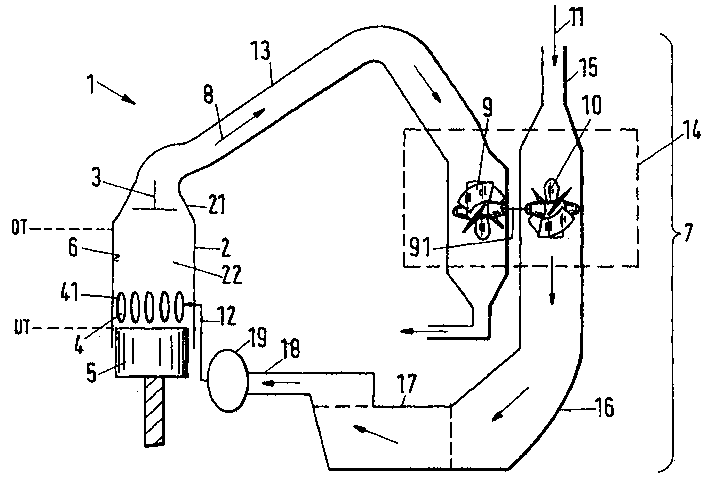
图1简要示出了一个带有一个增压器组的二冲程大型内燃机的重要部分;Figure 1 schematically shows the important parts of a large two-stroke internal combustion engine with a supercharger group;
图2简要示出了一种根据本发明的方法的一个实施例;和Figure 2 schematically illustrates an embodiment of a method according to the invention; and
图3简要示出了一个二冲程大型内燃机的带有一个进气阀的汽缸。Figure 3 schematically shows a cylinder of a large two-stroke internal combustion engine with one intake valve.
具体实施方式Detailed ways
图1简要示出了一个带有一个增压器组7的二冲程大型内燃机的重要部分,该增压器组作为一个具有延长扫气的二冲程发动机并作为一个在下文用参考标号1表示的整体设计。Figure 1 shows schematically the essential parts of a large two-stroke internal combustion engine with a supercharger group 7 as a two-stroke engine with extended scavenging and as a overall design.
大型柴油机1通常包括数个汽缸2,该汽缸具有一个汽缸盖21和一个布置在汽缸盖中的排气阀4,在汽缸2中布置有一个可在一个下死点位置UT和一个上死点位置OT之间沿一个运行表面6往复运动的活塞5,活塞5的上死点位置OT照常用一个0°或360°的曲柄转角KW表示,活塞5的下死点位置UT照常用一个180°的曲柄转角KW表示。汽缸2与汽缸盖21和活塞5按已经方式限定一个燃烧室22。在汽缸2的下部区域中,设置有数个设计为扫气槽41的扫气用空气开口4。扫气槽41根据活塞5的位置而被活塞盖住或被活塞释放。以扫气用空气12表示的新鲜空气可以经过扫气槽41流入汽缸2的燃烧室22。在燃烧室中产生的废气8经过布置在汽缸盖21中的排气阀3经与排气阀3相邻接的废气管13流入一个增压器组7。增压器组7作为重要构件按已知方式包括有一个用于压缩空气11的转子10和一个用于驱动转子10的涡轮9,转子10与涡轮9通过一个轴91以一种有效固定方式相连接。涡轮9和转子10布置在一个壳体中并构成一个涡轮增压器14。涡轮9由于来自汽缸2的燃烧室22的热废气8的流入而被驱动。为了用扫气用空气12增压汽缸2的燃烧室22,空气11通过转子10经过一个吸气管15被吸入并在涡轮增压器14中被压缩。压缩空气从涡轮增压器通过一个下游扩散器16和一个空气冷却器17经一个压力管路18运动到一个进气接收器19中,并且压缩终了的空气作为扫气用空气12在增加的压力下通过形成有扫气槽41的扫气用空气开口4从该处进入汽缸2的燃烧室2。A large diesel engine 1 generally comprises several cylinders 2 which have a
根据本发明的二冲程往复式内燃机1的处于低速时的工作方法,该速度低于一个图2中简要示出的用于一种二冲程大型柴油机1的预先设定的转速限值。为了解释用于执行根据本发明的方法的重要步骤,在图2中示出了一个完整的二冲程循环。在一个完整的二冲程循环中在八个选择的曲柄转角KW处示出了汽缸2的位置,其中0°的曲柄转角KW相应于活塞5的上死点位置OT,其中180°的曲柄转角KW相应于活塞5的下死点位置UT。由于根据本发明的方法是一种二冲程方法,所以0°的曲柄转角KW等于360°的曲柄转角KW。The method of operation of the two-stroke reciprocating internal combustion engine 1 according to the invention at low speeds below a predetermined speed limit for a two-stroke large diesel engine 1 schematically shown in FIG. 2 . In order to explain the important steps for carrying out the method according to the invention, a complete two-stroke cycle is shown in FIG. 2 . The position of cylinder 2 is shown at eight selected crank angles K W during a complete two-stroke cycle, where a crank angle K W of 0° corresponds to the top dead center position OT of piston 5 , where a crank angle of 180° Angle of rotation K W corresponds to bottom dead center position UT of piston 5 . Since the method according to the invention is a two-stroke method, a crank angle K W of 0° is equal to a crank angle K W of 360°.
在一曲柄转角K1处,汽缸2的燃烧室22中的燃烧在一个前面的压缩循环之后基本完成,从而在燃烧室22中可得到处于工作压力下的热燃烧气体,从而使汽缸2中的活塞5从曲柄转角K1处开始在一个膨胀循环中向相应于一个180°的曲柄转角KW的下死点位置UT方向运动。排气阀3在曲柄转角K1处关闭。在一个在进行燃料喷射并随后燃烧之后和在扫气用空气12随后进入汽缸2的燃烧室22之前开始的预扫气相位V中,即在活塞5在一个燃烧循环之后第一次释放扫气槽41以前,和在一个曲柄转角K2处,排气阀3随着预扫气相位V的开始而打开,即曲柄转角K2是如此选择的,从而当排气阀在曲柄转角K2处打开时,汽缸2的燃烧室22中压力仍很好地保持在废气管13中的压力之上。由于在燃烧室22和废气管13之间的压力差,热废气8通过废气管13流入涡轮增压器14,并在那驱动涡轮9,从而驱动转子10,如上所述,可得到作为用于引入汽缸2的燃烧室22中的扫气用空气13的压缩空气,该汽缸的扫气槽41同时被相应的活塞5释放。这意味着,废气8的热能中的一部分已经按已知方式被利用、通过在释放扫气槽41之前、即在扫气用空气12流入汽缸2的燃烧室22之前打开排气阀3来驱动涡轮增压器14的涡轮9了。At a crank angle K1 , the combustion in the combustion chamber 22 of cylinder 2 is substantially complete after a previous compression cycle, so that hot combustion gases at operating pressure are available in combustion chamber 22, so that the combustion in cylinder 2 Starting from crank angle K 1 , piston 5 moves during an expansion cycle in the direction of the bottom dead center position UT corresponding to a crank angle K W of 180°. Exhaust valve 3 closes at crank angle K1 . In a prescavenging phase V that begins after fuel injection and subsequent combustion and before the scavenging air 12 subsequently enters the combustion chamber 22 of the cylinder 2, ie the piston 5 releases the scavenging air for the first time after a combustion cycle Before groove 41, and at a crank angle K2 , the exhaust valve 3 opens with the start of the pre-scavenging phase V, i.e. the crank angle K2 is chosen so that when the exhaust valve is at the crank angle K2 When opening, the pressure in the combustion chamber 22 of the cylinder 2 remains well above the pressure in the
在一个略微大于曲柄转角K2的曲柄转角K3处,燃烧室22和废气管13之间的压力差基本上平衡,排气阀3在预扫气相位V中在曲柄转角K3处再次静止关闭。由于在燃烧室22和进气接收器19之间的最大压力差取决于曲柄转角KW,在该曲柄转角处排气阀3在预扫气相位V中再次关闭,在预扫气相位V中在释放扫气用空气开口4之后引入燃烧室2 2中的新鲜空气量由曲柄转角KW的预设值根据往复式内燃机1的转速、根据曲柄转角KW和/或汽缸2的燃烧室22中的气体压力和/或汽缸2的燃烧室22中的温度和/或增压器组7的转速和/或增压器组7中的气体压力和/或增压器组7中的温度和/或根据往复式内燃机1的其它工作参数控制和/或调节,在该曲柄转角处排气阀3在预扫气相位V中关闭。燃烧室22中封闭的体积由活塞5在汽缸2中向下死点位置UT方向的进一步运动而增加,从而燃烧室22中的压力由于排气阀3关闭而落到进气接收器19中的压力之下。在一个标注着预扫气相位V的结束的曲柄转角K4处,活塞5至少部分地释放扫气槽41,从而扫气用空气12可以流出进气接收器19而进入燃烧室22,排气阀3仍保持关闭。扫气用空气12由于燃烧室22中在预扫气相位V产生的负压而被吸入燃烧室22。这意味着,在一个预先设定的压力下通过进气接收器19将扫气用空气12引入汽缸2的燃烧室22的涡轮增压器14在其功能方面受到在活塞5在预扫气相位中的膨胀运动过程中在燃烧室22中产生的负压的支持。At a crank angle K3 which is slightly greater than the crank angle K2 , the pressure difference between the combustion chamber 22 and the
在一个接近下死点位置UT的曲柄转角K5处,和在活塞5到达下死点位置UT之前或之后,排气阀3打开,从而在下面的压缩循环中废气8可以通过排气阀3经废气管13供给增压器组7。在一个180°的曲柄转角处,排气阀3仍是打开的,并且一个压缩循环以一种已知的方式开始,在到达一个曲柄转角K6时使扫气槽41关闭,根据需要在一个在压缩循环中到达曲柄转角K6之前或之后的预先设定的时间、即在活塞已经经过下死点位置UT之后关闭排气阀3。在根据本发明的另一种变型方案中,排气阀3也可特别是在释放扫气开口4之后在活塞已经到达下死点位置UT之前再次关闭。通过活塞5向上死点位置OT方向的进一步运动,封闭在燃烧室22中的空气被压缩,燃料在一个预先设定的时间以众所周知的方式通过一个喷嘴(未示出)被引入燃烧室22中,接下来便是燃料/空气混合物在燃烧室22中的燃烧。At a crank angle K5 close to the bottom dead center position UT, and before or after the piston 5 reaches the bottom dead center position UT, the exhaust valve 3 opens so that exhaust gas 8 can pass through the exhaust valve 3 in the following compression cycle The supercharger group 7 is supplied through the
在这方面,排气阀3的致动可由一个自由可编程控制单元(未示出)根据往复式内燃机1的转速、根据曲柄转角KW和/或汽缸2的燃烧室22中的气体压力和/或汽缸2的燃烧室22中的温度和/或增压器组7的转速和/或增压器组7中的气体压力和/或增压器组7中的温度和/或根据往复式内燃机1的其它工作参数控制和/或调节。In this respect, the actuation of the exhaust valve 3 can be controlled by a freely programmable control unit (not shown) as a function of the rotational speed of the reciprocating internal combustion engine 1 , as a function of the crank angle K W and/or of the gas pressure in the combustion chamber 22 of the cylinder 2 and /or the temperature in the combustion chamber 22 of the cylinder 2 and/or the rotational speed of the supercharger group 7 and/or the gas pressure in the supercharger group 7 and/or the temperature in the supercharger group 7 and/or according to the reciprocating Other operating parameters of the internal combustion engine 1 are controlled and/or regulated.
根据本发明的二冲程往复式内燃机1的工作方法当然也可以成功地用于大型柴油机,其具有一个取代汽缸2的运行表面6中的作为一个扫气用空气开口4的扫气槽41的进气阀42,如图3所示。用一个以类似方式具有一个进气阀42的往复式内燃机1来执行根据本发明的方法。然而,尽管对于一个具有纵向扫气的大型柴油机1而言,扫气用空气开口4的释放、即扫气槽41的释放是由汽缸2中的活塞5的位置预先确定的,但对于一个具有进气阀42的大型柴油机1而言,进气阀42仍必须由一个控制装置致动。进气阀42的致动优选由一个自由可编程控制单元(未示出)根据往复式内燃机1的转速、根据曲柄转角KW和/或汽缸2的燃烧室22中的气体压力和/或汽缸2的燃烧室22中的温度和/或增压器组7的转速和/或增压器组7中的气体压力和/或增压器组7中的温度和/或根据往复式内燃机1的其它工作参数控制和/或调节。The working method of the two-stroke reciprocating internal combustion engine 1 according to the invention can of course also be successfully used in large diesel engines, which have a scavenging groove 41 instead of a scavenging
如上所述,优选在一个低于一个预先设定的转速限值的较低负载范围内的转速下使用早先说明的根据本发明的方法。当往复式内燃机1已经超过该转速限值、涡轮增压器14已经达到一个预先设定的功率时,往复式内燃机1便根据一个从现有技术已知的二冲程方法工作。As mentioned above, the method according to the invention described earlier is preferably used at a speed in the lower load range below a predetermined speed limit. When the reciprocating internal combustion engine 1 has exceeded this rotational speed limit and the turbocharger 14 has reached a predetermined output, the reciprocating internal combustion engine 1 operates according to a two-stroke method known from the prior art.
通过使用根据本发明的方法,避免了与用于在低负载工作时支持废气涡轮增压器的附加辅助增压器的使用相关的缺点。这样,不仅避免了对附加辅助增压器的,而且还避免了用于控制其所需的装置的购置和安装的努力。进气接收器的设计也变得不复杂了,这是因为特别是该进气接收器中的形式为片状件的回流阻挡件也可被省去。同样可以省去与工作资源、机器配件和人力的附加费用相关的服务和修理努力。特别是,通过使用根据本发明的方法可以节省大量的空间和重量。另外,从能量角度而言。不带有辅助涡轮增压器的往复内燃机的工作也是更有利的,因为不再需要得到用于它们工作的电能,并且可以节省最终重量。相当重要的是,根据本发明的方法的使用导致往复式内燃机的燃料消耗降低。By using the method according to the invention, the disadvantages associated with the use of an additional auxiliary supercharger for supporting the exhaust gas turbocharger during low-load operation are avoided. In this way, not only the acquisition and installation effort of an additional auxiliary supercharger, but also the devices required to control it, is avoided. The design of the intake receptacle is also less complicated, since in particular a backflow barrier in the form of a plate can also be omitted in the intake receptacle. Service and repair efforts associated with additional costs for working resources, machine parts and manpower can likewise be dispensed with. In particular, considerable space and weight can be saved by using the method according to the invention. Also, from an energy point of view. The operation of reciprocating internal combustion engines without auxiliary turbochargers is also more favorable, since it is no longer necessary to obtain electrical energy for their operation and the resulting weight can be saved. Of considerable importance, the use of the method according to the invention leads to a reduction in the fuel consumption of the reciprocating internal combustion engine.
Claims (9)
Applications Claiming Priority (2)
| Application Number | Priority Date | Filing Date | Title |
|---|---|---|---|
| EP02405578 | 2002-07-09 | ||
| EP02405578.2 | 2002-07-09 |
Publications (2)
| Publication Number | Publication Date |
|---|---|
| CN1472425A true CN1472425A (en) | 2004-02-04 |
| CN100538043C CN100538043C (en) | 2009-09-09 |
Family
ID=30129266
Family Applications (1)
| Application Number | Title | Priority Date | Filing Date |
|---|---|---|---|
| CNB031471935A Expired - Fee Related CN100538043C (en) | 2002-07-09 | 2003-07-08 | How two-stroke reciprocating internal combustion engines work |
Country Status (7)
| Country | Link |
|---|---|
| EP (1) | EP1380737B1 (en) |
| JP (2) | JP2004044593A (en) |
| KR (1) | KR101061862B1 (en) |
| CN (1) | CN100538043C (en) |
| DE (1) | DE50300453D1 (en) |
| DK (1) | DK1380737T3 (en) |
| PL (1) | PL361130A1 (en) |
Cited By (8)
| Publication number | Priority date | Publication date | Assignee | Title |
|---|---|---|---|---|
| CN101501310B (en) * | 2006-08-04 | 2011-06-22 | 丰田自动车株式会社 | Direct injection spark ignition internal combustion engine and fuel injection method thereof |
| CN101353979B (en) * | 2007-07-27 | 2012-10-03 | 瓦特西拉瑞士股份有限公司 | Two-stroke diesel combustion engine |
| CN102777248A (en) * | 2012-08-01 | 2012-11-14 | 陈卫文 | Two-stroke diesel engine |
| CN103026034A (en) * | 2010-08-05 | 2013-04-03 | 株式会社Ihi | two cycle engine |
| CN101666259B (en) * | 2008-09-03 | 2013-07-24 | 瓦特西拉瑞士股份有限公司 | Method for operating a longitudinally scavenged two-stroke large diesel engine |
| CN103249939A (en) * | 2010-12-09 | 2013-08-14 | 日立造船株式会社 | Two-stroke engine and four-stroke engine |
| CN103782006A (en) * | 2011-09-14 | 2014-05-07 | 三菱重工业株式会社 | Air-sweeping water droplet separator pollution prevention structure and ship equipped with the structure |
| CN112066416A (en) * | 2019-06-11 | 2020-12-11 | 斗山重工业建设有限公司 | Swirler with fuel manifold and combustor and gas turbine containing the same |
Families Citing this family (9)
| Publication number | Priority date | Publication date | Assignee | Title |
|---|---|---|---|---|
| JP4234695B2 (en) * | 2005-06-03 | 2009-03-04 | エムエーエヌ・ディーゼル・フィリアル・アフ・エムエーエヌ・ディーゼル・エスイー・ティスクランド | Large multi-cylinder two-cycle diesel engine |
| BRPI0703534A (en) * | 2006-10-30 | 2008-06-24 | Wortsilo Schweiz Ag | charge air cooler for an alternating piston combustion engine |
| KR20080074719A (en) | 2007-02-08 | 2008-08-13 | 베르트질레 슈바이츠 악티엔게젤샤프트 | A method for charging air in a cylinder of a 2-stroke large diesel engine scavenged in the longitudinal direction, and a 2-stroke large diesel engine scavenged in the longitudinal direction |
| ATE544940T1 (en) | 2007-02-12 | 2012-02-15 | Waertsilae Nsd Schweiz Ag | METHOD FOR OPERATING A LONGITUDINALLY SLUGGED TWO-STROKE LARGE DIESEL ENGINE, AND A LONGITUDINALLY SLUGGED TWO-STROKE LARGE DIESEL ENGINE |
| EP2098708A1 (en) * | 2008-03-06 | 2009-09-09 | Wärtsilä Schweiz AG | A method for the operation of a longitudinally scavenged two-stroke large diesel engine and a longitudinally scavenged two stroke large diesel engine |
| DK2112349T3 (en) * | 2008-04-21 | 2013-06-24 | Waertsilae Nsd Schweiz Ag | Rinse Performance Monitoring System and Method for Monitoring a Process Parameter for the Rinse Process for a Long Rinsed Large 2-Stroke Diesel Engine |
| DE102010004516B4 (en) * | 2010-01-13 | 2012-11-08 | Bernd Hopke | Method for operating an internal combustion engine |
| FR2991719B1 (en) * | 2012-06-12 | 2016-02-19 | IFP Energies Nouvelles | METHOD FOR SCANNING REDISOUS BURN GASES BY DOUBLE LIFTING OF VALVES FOR A TWO-STROKE ENGINE, IN PARTICULAR OF A DIESEL TYPE |
| JPWO2023228569A1 (en) * | 2022-05-24 | 2023-11-30 |
Family Cites Families (5)
| Publication number | Priority date | Publication date | Assignee | Title |
|---|---|---|---|---|
| US2820339A (en) * | 1952-03-31 | 1958-01-21 | Nordberg Manufacturing Co | Turbo-charged internal combustion engines and methods of starting and operating them |
| DE1121406B (en) * | 1960-03-15 | 1962-01-04 | Sulzer Ag | Two-stroke internal combustion engine with controlled exhaust valve and exhaust gas turbocharger |
| FR2589518B1 (en) * | 1985-11-06 | 1987-12-24 | Melchior Jean | IMPROVEMENTS ON TWO-STROKE INTERNAL COMBUSTION ENGINES AND METHOD OF IMPLEMENTING |
| DE59301711D1 (en) * | 1992-07-17 | 1996-04-04 | Avl Verbrennungskraft Messtech | Two-stroke internal combustion engine |
| JP2003138943A (en) * | 2001-10-30 | 2003-05-14 | Daihatsu Motor Co Ltd | Two-stroke internal combustion engine |
-
2003
- 2003-06-11 EP EP03405416A patent/EP1380737B1/en not_active Expired - Lifetime
- 2003-06-11 DE DE50300453T patent/DE50300453D1/en not_active Expired - Lifetime
- 2003-06-11 DK DK03405416T patent/DK1380737T3/en active
- 2003-06-17 KR KR1020030039158A patent/KR101061862B1/en not_active Expired - Fee Related
- 2003-07-07 PL PL03361130A patent/PL361130A1/en not_active Application Discontinuation
- 2003-07-08 JP JP2003193373A patent/JP2004044593A/en active Pending
- 2003-07-08 CN CNB031471935A patent/CN100538043C/en not_active Expired - Fee Related
-
2010
- 2010-03-01 JP JP2010044384A patent/JP2010151140A/en active Pending
Cited By (14)
| Publication number | Priority date | Publication date | Assignee | Title |
|---|---|---|---|---|
| CN101501310B (en) * | 2006-08-04 | 2011-06-22 | 丰田自动车株式会社 | Direct injection spark ignition internal combustion engine and fuel injection method thereof |
| CN101353979B (en) * | 2007-07-27 | 2012-10-03 | 瓦特西拉瑞士股份有限公司 | Two-stroke diesel combustion engine |
| CN101666259B (en) * | 2008-09-03 | 2013-07-24 | 瓦特西拉瑞士股份有限公司 | Method for operating a longitudinally scavenged two-stroke large diesel engine |
| US8972151B2 (en) | 2010-08-05 | 2015-03-03 | Ihi Corporation | Two-cycle engine |
| CN103026034A (en) * | 2010-08-05 | 2013-04-03 | 株式会社Ihi | two cycle engine |
| CN103026034B (en) * | 2010-08-05 | 2015-08-05 | 株式会社Ihi | Two-cycle engine |
| CN103249939B (en) * | 2010-12-09 | 2015-09-09 | 日立造船株式会社 | Two-stroke and four-stroke engines |
| CN103249939A (en) * | 2010-12-09 | 2013-08-14 | 日立造船株式会社 | Two-stroke engine and four-stroke engine |
| US9404412B2 (en) | 2010-12-09 | 2016-08-02 | Hitachi Zosen Corporation | Two-stroke engine and four-stroke engine |
| CN103782006A (en) * | 2011-09-14 | 2014-05-07 | 三菱重工业株式会社 | Air-sweeping water droplet separator pollution prevention structure and ship equipped with the structure |
| CN103782006B (en) * | 2011-09-14 | 2017-07-28 | 三菱重工业株式会社 | Air-sweeping water droplet separator pollution prevention structure and ship equipped with the structure |
| CN102777248A (en) * | 2012-08-01 | 2012-11-14 | 陈卫文 | Two-stroke diesel engine |
| CN112066416A (en) * | 2019-06-11 | 2020-12-11 | 斗山重工业建设有限公司 | Swirler with fuel manifold and combustor and gas turbine containing the same |
| US11953205B2 (en) | 2019-06-11 | 2024-04-09 | Doosan Enerbility Co., Ltd. | Swirler with fuel manifold, and combustor and gas turbine including the same |
Also Published As
| Publication number | Publication date |
|---|---|
| JP2010151140A (en) | 2010-07-08 |
| DK1380737T3 (en) | 2005-07-25 |
| KR101061862B1 (en) | 2011-09-02 |
| DE50300453D1 (en) | 2005-05-25 |
| JP2004044593A (en) | 2004-02-12 |
| EP1380737A1 (en) | 2004-01-14 |
| CN100538043C (en) | 2009-09-09 |
| EP1380737B1 (en) | 2005-04-20 |
| KR20040005588A (en) | 2004-01-16 |
| PL361130A1 (en) | 2004-01-12 |
Similar Documents
| Publication | Publication Date | Title |
|---|---|---|
| CN1107794C (en) | Supercharging systems for four-stroke internal combustion engines | |
| CN1097147C (en) | Charge air systems for two-cycle internal combustion engines | |
| JP2010151140A (en) | Operation method for two-stroke reciprocation internal combustion engine | |
| JP2011064201A (en) | Method for operating reciprocating internal combustion engine | |
| CN1080359A (en) | Apparatus for exhaust gas recirculation via reverse flow motoring and method | |
| JPS6128815B2 (en) | ||
| KR19990067651A (en) | Supercharger system for 4 cycle internal combustion engine | |
| JP2011149428A (en) | Residual combustion gas scavenging method in direct-injection supercharged internal-combustion multi-cylinder engine running under partial load | |
| CN1269866A (en) | Internal combustion engine with exhaust and charge gas recirculation | |
| CN1298981C (en) | Control strategy for turbocharged engine having variable valve actuation apparatus | |
| WO2005068804A1 (en) | A two-stroke compression ignition engine | |
| CN1910355A (en) | A turbocharged internal combustion engine | |
| CN110832177B (en) | Method for operating an internal combustion engine, internal combustion engine | |
| CN1207156A (en) | Charge air systems for four-cycle internal combustion engines | |
| CN113924414B (en) | Method for starting operation of an internal combustion engine, internal combustion engine, vehicle and control unit | |
| US11698022B1 (en) | Modified cycle two-stroke engine | |
| EP0846848A1 (en) | Two-stroke Twin-injector-per-cylinder engine | |
| CN87103277A (en) | Improvement of two-stroke internal combustion engine and its operating method | |
| CN1260469C (en) | Waste gas turbocharged I.C. engine | |
| KR101734169B1 (en) | A method for the operation of a longitudinally scavenged two stroke large diesel engine | |
| JPS58167823A (en) | Diesel engine with supercharger | |
| CN209129734U (en) | Two-stroke diesel aero engine | |
| EP4519543A1 (en) | Separate compressor arrangements for engines | |
| RU2002104409A (en) | INTERNAL COMBUSTION ENGINE (options) | |
| JPH0533672A (en) | 2-4 cycle switching turbo compound engine |
Legal Events
| Date | Code | Title | Description |
|---|---|---|---|
| C06 | Publication | ||
| PB01 | Publication | ||
| C10 | Entry into substantive examination | ||
| SE01 | Entry into force of request for substantive examination | ||
| C14 | Grant of patent or utility model | ||
| GR01 | Patent grant | ||
| C17 | Cessation of patent right | ||
| CF01 | Termination of patent right due to non-payment of annual fee |
Granted publication date: 20090909 Termination date: 20120708 |