CN1496578A - Mercury discharge lamp - Google Patents
Mercury discharge lamp Download PDFInfo
- Publication number
- CN1496578A CN1496578A CNA028061454A CN02806145A CN1496578A CN 1496578 A CN1496578 A CN 1496578A CN A028061454 A CNA028061454 A CN A028061454A CN 02806145 A CN02806145 A CN 02806145A CN 1496578 A CN1496578 A CN 1496578A
- Authority
- CN
- China
- Prior art keywords
- discharge lamp
- gas
- discharge
- krypton
- mercury
- Prior art date
- Legal status (The legal status is an assumption and is not a legal conclusion. Google has not performed a legal analysis and makes no representation as to the accuracy of the status listed.)
- Pending
Links
Images


Classifications
-
- H—ELECTRICITY
- H01—ELECTRIC ELEMENTS
- H01J—ELECTRIC DISCHARGE TUBES OR DISCHARGE LAMPS
- H01J61/00—Gas-discharge or vapour-discharge lamps
- H01J61/02—Details
- H01J61/30—Vessels; Containers
- H01J61/32—Special longitudinal shape, e.g. for advertising purposes
- H01J61/325—U-shaped lamps
-
- H—ELECTRICITY
- H01—ELECTRIC ELEMENTS
- H01J—ELECTRIC DISCHARGE TUBES OR DISCHARGE LAMPS
- H01J61/00—Gas-discharge or vapour-discharge lamps
- H01J61/70—Lamps with low-pressure unconstricted discharge having a cold pressure < 400 Torr
- H01J61/72—Lamps with low-pressure unconstricted discharge having a cold pressure < 400 Torr having a main light-emitting filling of easily vaporisable metal vapour, e.g. mercury
-
- H—ELECTRICITY
- H01—ELECTRIC ELEMENTS
- H01J—ELECTRIC DISCHARGE TUBES OR DISCHARGE LAMPS
- H01J61/00—Gas-discharge or vapour-discharge lamps
- H01J61/70—Lamps with low-pressure unconstricted discharge having a cold pressure < 400 Torr
- H01J61/76—Lamps with low-pressure unconstricted discharge having a cold pressure < 400 Torr having a filling of permanent gas or gases only
Landscapes
- Discharge Lamp (AREA)
- Circuit Arrangements For Discharge Lamps (AREA)
Abstract
一种放电装置,包括充满含汞放电气体的透明外壳;和通过施加电场激发气体的电极。已发现的是,如果除汞蒸汽外的气体是约99%的氩和数量级为0.1~1%的氪,则与254nm线相比,近可见UV线的比例增加,特别是如果采用脉冲激发。这就提高了灯在用于激发可见光荧光体时的发光效率。
A discharge device includes a transparent housing filled with a mercury-containing discharge gas; and electrodes for exciting the gas by applying an electric field. It has been found that if the gas, excluding mercury vapor, is approximately 99% argon and on the order of 0.1–1% krypton, the proportion of near-visible UV lines increases compared to the 254 nm line, especially if pulsed excitation is used. This improves the luminous efficiency of the lamp when used to excite visible phosphors.
Description
标准白光荧光灯几乎普遍利用衬以磷的混合物的玻璃管中的汞放电,磷的混合物在受到汞放电之辐射的激发时,发出一系列可见光波长。尽管这是一种相当有效的产生白光的方式,但一个缺点是,大部分可见范围磷是由254nm的明显汞辐射而激发的,因此对于可见磷发光的转换需要大量的能量损耗。Standard white fluorescent lamps almost universally utilize a mercury discharge in a glass tube lined with a phosphorous mixture that, when excited by radiation from the mercury discharge, emits a range of visible wavelengths. Although this is a fairly efficient way of generating white light, one disadvantage is that most of the visible range phosphor is excited by the apparent mercury radiation at 254 nm, thus requiring a large energy loss for the conversion of visible phosphorescence.
在UV附近中的365nm附近发生一组汞辐射。放电最好是主要以此波长而不是254nm发出辐射,因为在磷激发和可见光的发射中伴随的能量损耗会明显减少。发明人早先的申请WO 99/04605解决了这一问题;在此申请文件中,气体的激发是借助于较长间隔(约100μs)的极短(约1μs)脉冲。因此在脉冲期间,放电没有时间建立其“准稳定状态”,与放电被连续激发时相比,很多高能汞浓度出现为更高的比例。当脉冲被断开时,这些高能状态衰退,在余晖期间引起365nm辐射的优势。这项技术能够使更高波长等离子体波长发光的比例提高100%或更高。A set of mercury radiation occurs near 365nm in the UV vicinity. The discharge preferably radiates predominantly at this wavelength rather than at 254 nm, since the attendant energy losses in phosphor excitation and emission of visible light are significantly reduced. The inventor's earlier application WO 99/04605 solved this problem; in this application the gas was excited by means of very short (about 1 μs) pulses at longer intervals (about 100 μs). Thus during the pulse, the discharge does not have time to establish its "quasi-steady state", and much higher energetic mercury concentrations occur in higher proportions than when the discharge is continuously excited. When the pulse is switched off, these high-energy states decay, giving rise to a predominance of 365nm radiation during afterglow. This technology enables a 100 percent or greater increase in the proportion of light emitted at higher wavelength plasma wavelengths.
根据本发明,提供一种放电灯,包括:一透明外壳,充满含汞的放电气体;和一激发装置,其通过施加电场激发气体,其中除了汞蒸汽外,气体为大约99%的氩和数量级为0.1~1%的氪。According to the present invention, there is provided a discharge lamp comprising: a transparent envelope filled with a mercury-containing discharge gas; and an excitation device which excites the gas by applying an electric field, wherein the gas is about 99% argon and the order of It is 0.1-1% krypton.
现已发现,用氪来代替一小部分普通的氩“缓冲剂”大大增加了余辉中高波长汞线的比率。考虑到此效果可能是由于一方面较低氪浓度(level)与较高汞浓度的重叠,另一方面是较高氪浓度与较低氩浓度(见图3中的箭头),因此提供用于能量传递到高汞浓度的一种桥路。It has now been found that replacing a small portion of the ordinary argon "buffer" with krypton greatly increases the proportion of high wavelength mercury lines in the afterglow. Considering that this effect may be due to the overlap of lower krypton levels with higher mercury concentrations on the one hand, and higher krypton concentrations with lower argon concentrations on the other (see arrows in Figure 3), it is provided for A bridge of energy transfer to high mercury concentrations.
氪与氩的比率的最有效范围是约0.2~0.8%,降低较多,效果可以忽略,更高,氪抑制放电并形成射束。压力可以是在5~45Torr(托)的范围内,最好是约为25Torr。The most effective range for the ratio of krypton to argon is about 0.2-0.8%, the lower the effect is negligible, the higher the krypton suppresses the discharge and forms the beam. The pressure may be in the range of 5 to 45 Torr, preferably about 25 Torr.
气体混合物仅对出现余辉效果的脉冲放电是有效的,典型的是采用2~20kHz的脉冲频率和1~10%的负载比(即,脉冲宽度=脉冲间隔的1~10%)。The gas mixture is only effective for pulsed discharges where an afterglow effect occurs, typically with a pulse frequency of 2-20 kHz and a duty ratio of 1-10% (ie pulse width = 1-10% of pulse interval).
为了更好地理解本发明,以下将通过示例并参考附图描述实施例,其中:For a better understanding of the present invention, embodiments will be described below by way of example and with reference to the accompanying drawings, in which:
图1示出根据本发明实施例的放电中通过365nm线所确定的余辉效果的测量结果;Fig. 1 shows the measurement results of the afterglow effect determined by the 365nm line in the discharge according to an embodiment of the present invention;
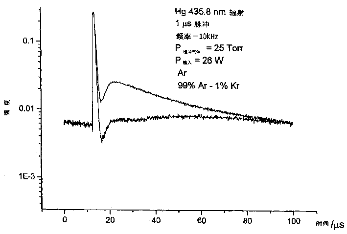
图2示出436nm线的相似测量结果;Figure 2 shows similar measurements for the 436nm line;
图3示出相关元件的相对能级;及Figure 3 shows the relative energy levels of the relevant elements; and
图4示出结合本发明使用的放电灯的示意图。Figure 4 shows a schematic diagram of a discharge lamp used in connection with the invention.
将1μs脉冲施加于放电介质,该放电介质包括99%的氩和1%的氪之惰性气体,以及蓄积的汞,该脉冲是由一控制单元以约500V的电压和10kHz的频率产生的。在图1中示出的结果迹线示出当施加脉冲时电压的起始上升,然后其下降至零并为等同的陡降,并产生余辉。上部迹线表示氩氪结果,而下部是与100%氩和汞的比较试验。如图中所示,在余辉的最“有成效”的部分上,纯氩放电的输出也许是混合物的输出。A 1 μs pulse was applied to a discharge medium consisting of an inert gas of 99% argon and 1% krypton, and accumulated mercury, generated by a control unit at a voltage of about 500 V and a frequency of 10 kHz. The resulting trace shown in Figure 1 shows an initial rise in voltage when the pulse is applied, then it falls to zero with an equivalent steep drop and an afterglow. The upper trace represents the argon-krypton results, while the lower is a comparative run with 100% argon and mercury. As shown in the graph, over the most "productive" part of the afterglow, the output of the pure argon discharge is perhaps that of the mixture.
此结果在图2中比较436nm线被测量的情况甚至更为显著。这些可见线也是有价值的:它们通常不会被用于激发荧光物质,但如果仔细选择荧光物质以提供好的波长平衡,它们作为可见光可以是直接有用的。本发明的效果概括地是改进254nm以上的所有发射。This result is even more pronounced in Figure 2 compared to the case where the 436nm line was measured. These visible lines are also valuable: they are not normally used to excite phosphors, but they can be directly useful as visible light if the phosphors are carefully chosen to provide a good wavelength balance. The effect of the invention is broadly to improve all emissions above 254 nm.
图3示出惰性气体和汞的普通激发状态的相对波长。可以看出,在氩的激发状态和汞的激发状态之间有一个间隙;应考虑到氪有效地跨过此间隙,并用作能量储存器。Figure 3 shows the relative wavelengths of common excited states for noble gases and mercury. It can be seen that there is a gap between the excited states of argon and mercury; it should be taken into account that krypton effectively spans this gap and acts as an energy store.
图4示出一种试验性的放电灯,其具有玻璃外壳1、阳极3、阴极5和局部荧光粉内衬7。该荧光粉内衬是一种荧光粉的混合物,其被选择在(特别是)受到365nm辐射的激发时在可见光范围发光,在一个工作灯中明显覆盖外壳的整个内壁。FIG. 4 shows an experimental discharge lamp with a
Claims (6)
Applications Claiming Priority (2)
| Application Number | Priority Date | Filing Date | Title |
|---|---|---|---|
| GBGB0105491.5A GB0105491D0 (en) | 2001-03-06 | 2001-03-06 | Mercury discharge lamps |
| GB0105491.5 | 2001-03-06 |
Publications (1)
| Publication Number | Publication Date |
|---|---|
| CN1496578A true CN1496578A (en) | 2004-05-12 |
Family
ID=9910062
Family Applications (1)
| Application Number | Title | Priority Date | Filing Date |
|---|---|---|---|
| CNA028061454A Pending CN1496578A (en) | 2001-03-06 | 2002-03-06 | Mercury discharge lamp |
Country Status (7)
| Country | Link |
|---|---|
| US (1) | US20040155598A1 (en) |
| EP (1) | EP1368819A1 (en) |
| JP (1) | JP2004528680A (en) |
| CN (1) | CN1496578A (en) |
| CA (1) | CA2440109A1 (en) |
| GB (1) | GB0105491D0 (en) |
| WO (1) | WO2002071441A1 (en) |
Families Citing this family (2)
| Publication number | Priority date | Publication date | Assignee | Title |
|---|---|---|---|---|
| CN100356500C (en) * | 2002-12-05 | 2007-12-19 | 鸿富锦精密工业(深圳)有限公司 | Plasma display panel |
| US6894438B2 (en) * | 2002-12-13 | 2005-05-17 | General Electric Company | Lighting system and method incorporating pulsed mode drive for enhanced afterglow |
Family Cites Families (16)
| Publication number | Priority date | Publication date | Assignee | Title |
|---|---|---|---|---|
| CA969598A (en) * | 1971-11-12 | 1975-06-17 | Hitoshi Otsuka | Fluorescent tube for lamp |
| US4247800A (en) * | 1979-02-02 | 1981-01-27 | Gte Laboratories Incorporated | Radioactive starting aids for electrodeless light sources |
| US4308650A (en) * | 1979-12-28 | 1982-01-05 | Gte Products Corporation | Method of making a mercury dispenser, getter and shield assembly for a fluorescent lamp |
| JPS56167251A (en) * | 1980-05-27 | 1981-12-22 | Toshiba Corp | Fluorescent lamp |
| JPS6034223B2 (en) * | 1980-06-18 | 1985-08-07 | 株式会社東芝 | metal vapor discharge lamp |
| JPS5760655A (en) * | 1980-09-29 | 1982-04-12 | Toshiba Corp | Fluorescent lamp |
| CA2006034C (en) * | 1988-12-27 | 1995-01-24 | Takehiko Sakurai | Rare gas discharge fluorescent lamp device |
| KR920010666B1 (en) * | 1989-06-13 | 1992-12-12 | 미쯔비시 덴끼 가부시기가이샤 | Low pressure rare gas discharge lamp |
| FR2674768B1 (en) * | 1991-04-02 | 1994-09-02 | France Telecom | PROCESS FOR THE PHOTOCHEMICAL TREATMENT OF A MATERIAL USING A LIGHT SOURCE WITH LIGHT TUBES. |
| US5328823A (en) * | 1992-11-27 | 1994-07-12 | American Air Liquide | Enzyme-based biosensors for detecting noble gases |
| JPH09504902A (en) * | 1993-11-03 | 1997-05-13 | サイエンス アプリケーションズ インターナショナル コーポレイション | High efficiency UV backlight system for backlighting of electronic display devices |
| US5592052A (en) * | 1995-06-13 | 1997-01-07 | Matsushita Electric Works R&D Laboratory | Variable color temperature fluorescent lamp |
| GB9714785D0 (en) * | 1997-07-14 | 1997-09-17 | Sheffield University | Discharge lamp |
| US6144175A (en) * | 1997-11-05 | 2000-11-07 | Parra; Jorge M. | Low-voltage ballast-free energy-efficient ultraviolet material treatment and purification system and method |
| JP2002251979A (en) * | 2001-02-23 | 2002-09-06 | Orc Mfg Co Ltd | Short arc type discharge lamp |
| US6683407B2 (en) * | 2001-07-02 | 2004-01-27 | General Electric Company | Long life fluorescent lamp |
-
2001
- 2001-03-06 GB GBGB0105491.5A patent/GB0105491D0/en not_active Ceased
-
2002
- 2002-03-06 WO PCT/GB2002/001034 patent/WO2002071441A1/en not_active Ceased
- 2002-03-06 CN CNA028061454A patent/CN1496578A/en active Pending
- 2002-03-06 US US10/471,146 patent/US20040155598A1/en not_active Abandoned
- 2002-03-06 EP EP02704925A patent/EP1368819A1/en not_active Withdrawn
- 2002-03-06 CA CA002440109A patent/CA2440109A1/en not_active Abandoned
- 2002-03-06 JP JP2002570266A patent/JP2004528680A/en active Pending
Also Published As
| Publication number | Publication date |
|---|---|
| WO2002071441A1 (en) | 2002-09-12 |
| JP2004528680A (en) | 2004-09-16 |
| CA2440109A1 (en) | 2002-09-12 |
| US20040155598A1 (en) | 2004-08-12 |
| GB0105491D0 (en) | 2001-04-25 |
| EP1368819A1 (en) | 2003-12-10 |
Similar Documents
| Publication | Publication Date | Title |
|---|---|---|
| CA2157208C (en) | Neon fluorescent lamp and method of operating | |
| JP4460799B2 (en) | Plasma display panel using excimer gas | |
| JP2002124211A (en) | Low pressure gas discharge lamp | |
| JP5129674B2 (en) | Light emitting device | |
| CN1159954C (en) | discharge lamp | |
| CN1180456C (en) | Low pressure mercury vapor discharge lamps | |
| US20040155598A1 (en) | Mercury discharge lamps | |
| US5637965A (en) | Low pressure sodium-mercury lamp yielding substantially white light | |
| JPH08306341A (en) | Fluorescent lamp | |
| US6777867B2 (en) | Highly loaded fluorescent lamp | |
| JPH05242870A (en) | Discharge lamp | |
| JP5346310B2 (en) | Light emitting device | |
| JP4258368B2 (en) | Electrodeless discharge lamp | |
| JP3404987B2 (en) | Electrodeless discharge lamp | |
| JPH1125916A (en) | Cold cathode fluorescent lamps and lighting devices | |
| JPH08273620A (en) | Fluorescent lamp, lighting device thereof, light source device using the same, and liquid crystal display device | |
| JPH11191393A (en) | Discharge lamps and lighting devices | |
| JPH0448547A (en) | light emitting device | |
| WO2002071440A1 (en) | Discharge lamps using near-uv emitters | |
| JP2004055521A (en) | Discharge lamp device and backlight using the same | |
| JPH11111028A (en) | Bulb shaped fluorescent lamp | |
| JP2011154906A (en) | Light-emitting device | |
| JPH0311055B2 (en) | ||
| JP2001135277A (en) | Rare gas fluorescent lamp | |
| JP2002063868A (en) | Fluorescent lamps and lighting devices |
Legal Events
| Date | Code | Title | Description |
|---|---|---|---|
| C06 | Publication | ||
| PB01 | Publication | ||
| C10 | Entry into substantive examination | ||
| SE01 | Entry into force of request for substantive examination | ||
| C02 | Deemed withdrawal of patent application after publication (patent law 2001) | ||
| WD01 | Invention patent application deemed withdrawn after publication |