CN1499433A - Device for coding and recognizing intelligent card - Google Patents
Device for coding and recognizing intelligent card Download PDFInfo
- Publication number
- CN1499433A CN1499433A CNA021450927A CN02145092A CN1499433A CN 1499433 A CN1499433 A CN 1499433A CN A021450927 A CNA021450927 A CN A021450927A CN 02145092 A CN02145092 A CN 02145092A CN 1499433 A CN1499433 A CN 1499433A
- Authority
- CN
- China
- Prior art keywords
- label
- bayonet lock
- slide rail
- groove
- flank
- Prior art date
- Legal status (The legal status is an assumption and is not a legal conclusion. Google has not performed a legal analysis and makes no representation as to the accuracy of the status listed.)
- Pending
Links
- 230000008093 supporting effect Effects 0.000 claims description 12
- 230000005294 ferromagnetic effect Effects 0.000 claims description 8
- 230000005484 gravity Effects 0.000 claims description 2
- 230000035939 shock Effects 0.000 claims description 2
- 239000006096 absorbing agent Substances 0.000 claims 1
- 210000003141 lower extremity Anatomy 0.000 claims 1
- 230000005291 magnetic effect Effects 0.000 abstract description 8
- 210000001364 upper extremity Anatomy 0.000 description 4
- 239000000463 material Substances 0.000 description 3
- 230000006835 compression Effects 0.000 description 2
- 238000007906 compression Methods 0.000 description 2
- 239000004020 conductor Substances 0.000 description 2
- 230000000694 effects Effects 0.000 description 2
- 230000009286 beneficial effect Effects 0.000 description 1
- 238000009434 installation Methods 0.000 description 1
- 238000009413 insulation Methods 0.000 description 1
- 239000007769 metal material Substances 0.000 description 1
- 230000004048 modification Effects 0.000 description 1
- 238000012986 modification Methods 0.000 description 1
- 230000003449 preventive effect Effects 0.000 description 1
- 230000002459 sustained effect Effects 0.000 description 1
- 229910000859 α-Fe Inorganic materials 0.000 description 1
Images

Landscapes
- Lock And Its Accessories (AREA)
Abstract
The device includes slide rail and tag. There is longitudinal groove on side of each slide rail. Tag possesses fin set in the groove and possesses bayonet lock set in the groove. The bayonet lock is supported by spring. Movable magnetic circuit guarantees relieving lock of the tag.
Description
Technical field
The present invention relates to a kind of electronic label device, especially a kind of smart card encoding identification device.
Background technology
Electronic tag is very general, especially in the megastore.The flat elongate slot that these markets have been equipped with many metal materials is with as the display rack for the treatment of vending articles.In general, the edge bearing of flat elongate slot the slide rail of an ambroin material, is provided with the power supply conductor of some display labels in slide rail inside.On slide rail, settling many electronic tags by holding parts.When these labels were in the position that has held, their contact was in the slide rail conductor and is electrically connected, and for example they just can show price, size.When a label is undesirable, with regard to removed and replacing.In order to change label, typically use a kind of instrument, it works in the side of label.When can be,,, use this instrument to be easy to take away label perhaps in order to collect label perhaps because of malicious act near the side of label.For fear of stealing label, wish that label possesses almost really accurate characteristic, in other words, label only should use special instrument just can take off.These preventive measure have shortcoming sometimes, and in order to increase reliability, some label just can't take off from the position of slide rail.In fact, in order to take off label, also must make at label to be removed and take off all label slippage between the position of label.Also have, these labels can't be fixed on the ad-hoc location, and they are easy to slide.This has upset the demonstration on shelf.
Summary of the invention
Technical matters to be solved by this invention provides a kind of smart card encoding identification device, and wherein label should be fixed on the desirable position by holding parts, also should not be easy to move.Another object of the present invention provides a kind of electronic tag display device, and wherein label should be easy to be taken off by a kind of instrument very easy to use.
The present invention relates to the solution technical scheme that its technical matters adopted: this device comprises the supporting slide rail of label, at least one electronic display tag, and the energy supply device of label, it is characterized in that, the supporting slide rail of one label comprises two aspectant flanks that extend longitudinally, and each flank has a longitudinal fluting at its medium position; And electronic tag in its two opposite edges one of have vertical fin on the edge, it is used for being embedded into the groove of one of them slide rail flank; Have at least one retractible bayonet lock on another of described opposite two edges, it is used for snapping to the groove of another flank of slide rail.
The invention has the beneficial effects as follows: bayonet lock is by spring-loaded, and movably magnetic circuit has guaranteed unlocking of label.
Description of drawings
Fig. 1 is the cross sectional representation that is used for the insulation slide rail embodiment of smart card encoding identification device of the present invention;
Fig. 2 is the cross sectional representation that is suitable for the electronic display tag embodiment of Fig. 1 slide rail;
Fig. 3 is the cross sectional representation of Fig. 1 slide rail when label releasing parts are in place that Fig. 2 label is housed:
Fig. 4 is the front view before taking out according to the another embodiment of the present invention label segment;
Fig. 5 removes parts when in place when label, along the sectional view of the A-A line of Fig. 4:
Fig. 6 is the top view that is suitable for the releasing parts embodiment of Fig. 4 label.
Embodiment
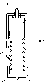
Fig. 1 has represented ambroin slide rail 1.This slide rail is U type structure, have flat 2, upper limb 3 and bottom wing 4.On outline, flat 2 and each flank 3,4 between be respectively equipped with otch 5,6.Bottom wing 4 medium position of side within it has a longitudinal fluting 10.The end 11 of bottom wing 4 is a circular arc.Upper limb 3 medium position of side within it also has a longitudinal fluting 12, has arranged some blind holes 33 with uniform interval in groove 12.The end 13 of upper limb 3 has outer arc 14 and inboard chamfering 15.A vertical grooving 16 is preferably arranged on the centre position of the bottom inside face 7 of slide rail 1, for example can be used for settling some that slide rail 1 is fixed on stationary installation on its supporting member.
In Fig. 2, represented the cross sectional view of electronic display tag 20 in an xsect of its bayonet lock structure.Label 20 is the cuboid shape, can see unique xsect from Fig. 3.Label 20 comprises the thin outer crust 25 of plastic material, can see its four surfaces at Fig. 3, is respectively rear surface 21, front surface 22, lower surface 23 and upper surface 24.Front surface 22 is transparent, can see the LCDs of for example being controlled by microprocessor, and it cooperates price or the information of demonstrating with the central computer in shop.Lower surface 23 position in the middle has preferably vertical fin 26 of arc-shaped surface.This fin 26 is used for being embedded into the groove 10 of slide rail 1 bottom wing 4.In the inboard of shell 25, label 20 comprises at least one cavity 27, and it extends at least a portion label height, and is used to settle the bayonet lock parts in the cavity 27.In Fig. 2 embodiment, these bayonet lock parts comprise the volute spring 28 that is placed in cavity 27 bottoms, push the ferromagnetic core 29 at top to by spring 28, and bayonet lock 30, and bayonet lock 30 is by core body 29 supportings and can stretch out the hole 31 of passing label 20 upper surfaces 24.In the bottom of bayonet lock 30, between the shell 25 of ferromagnetic core 29 and label 20, a bump shock ring 32 is set preferably.For label 20 is encased in the slide rail 1, the bottom of label 20 at first occurs in the groove 10 that fin 26 is embedded into guide rail 1.The top of label 20 is pushed to the bottom of slide rail 1, and fin 26 has served as axis of swing.Bayonet lock 30 abuts on the inboard fillet surface 15, and this fillet surface 15 is pushed bayonet lock the inside of label 20 to and made spring 28 compressions.When label 20 during near its normal working position, bayonet lock 30 penetrates under the effect of spring 28 in the groove 12 of upper limb 3 of slide rail 1, and this moment, label 20 was in its working position.By slip label 20 is moved along slide rail 1 then, under the effect of spring 28, penetrate in one of them blind hole 33 up to bayonet lock 30.These blind holes are to each other apart from for example about 1cm, and this moment, label 20 was in its latched position.
In Fig. 3, shown slide rail 1 and label 20 are in its normal working position.Before the lock-out state of removing label 20, the approximated position shown in label releasing parts 43 are in.This approximated position is parallel to slide rail and label.The releasing parts 43 of label mainly comprise the housing 44 of plastic material, and the magnetic circuit that is made of magnet 45 and Ferrite 46.Housing 44 is the cuboid shape, has two arms 47,48, and they surround slide rail 1 and can rest on the supporting member 49 of slide rail 1.When two arms 47,48 rest on the supporting member of slide rail 1, and housing 44 is when being positioned at the label front, and magnetic circuit has one basically in the face of the gap of ferromagnetic core 29 bottoms.Core body 29 is attracted to the bottom then, and it moves and compression spring 28, thereby bayonet lock 30 has left the blind hole 33 and the groove 12 at place when its latched position along with the moving of core body 29.So just discharged label 20, it abuts on the housing 44 and in company with the releasing campaign of housing 44 and moves together.Then just can be from the manual label 20 that takes off on the housing 44; Core body 29 is promoted once more by spring 28, and bayonet lock turns back to the position of its housing that stretches out label 20 25 outsides.Housing 44 can include only single armed 47 or 48, in this case, housing arrives its correct position to be the supporting member 49 by clinging to slide rail 1 simultaneously and to cling to slide rail from realizing that on one's body for example, side direction clings on the flank 3 or 4 of slide rail 1 respectively.In that being set on the housing 44, at least one arm 47,48 guaranteed that magnetic circuit 45-46 navigates on the correct position automatically with respect to ferromagnetic core 29, so that remove the locking of label.Then, attract ferromagnetic core 29 by magnetic circuit 45.46, it makes label be affixed to housing 44, and 44 of housings play a part label and keep body.
As can be seen from Figure 4, because bayonet lock 130 just makes bayonet lock 130 reach the outside of lower edge 123 because of the gravity that is applied on bayonet lock and the core body 129, the spring of first kind of embodiment just can have been cancelled.Space 133 and otch 134 are in sustained height, and along cavity 127 with respect to core body 129 dislocation, remove parts 143 with box lunch and core body inhaled when in place and hoist.
Can see that referring to Fig. 6 remove parts 143 U-shaped in general, the relative magnet of magnetic pole 145 is being supported in its side arm inboard separately, so that produce the magnetic circuit that ferromagnetic core 129 is inhaled toward eminence.In the embodiment of Fig. 7, the bottom of U-shaped supporting member 144 is connecting a handle of being convenient to control 146.As a modification, when the label 120 of Fig. 4 when direction is used top down, also can be for cavity 127 is equipped with the spring similar with aforementioned spring 28, so that push bayonet lock 130 to eminence.On the contrary, when slide rail 1 in Fig. 1~3 embodiments and label 20 direction use top down, also can save the spring 28 in this embodiment.
Claims (7)
1. smart card encoding identification device, it comprises the supporting slide rail of label, at least one electronic display tag, and the energy supply device of label, it is characterized in that, the supporting slide rail of label comprises two aspectant flanks that extend longitudinally, and each flank has a longitudinal fluting at its medium position; And having vertical fin on the edge at opposite two edges of an electronic tag, they are used for being embedded into the groove of one of them slide rail flank; Have at least one retractible bayonet lock on another of described opposite two edges, they are used for another flank of slide rail is snapped to groove.
2. device according to claim 1 is characterized in that each bayonet lock is accommodated in one of them blind hole of a series of blind holes, these blind holes with uniform pitch arrangement in the groove of described another flank of slide rail.
3. device according to claim 1 is characterized in that the longitudinal fluting of described another flank of slide rail is used for matching with bayonet lock, and its groove has zigzag vertical side, and the spacing between two teeth can be held bayonet lock, so that fix label.
4. device according to claim 1 is characterized in that electronic display tag comprises at least one cavity, has settled the ferromagnetic core that is supporting bayonet lock in cavity, and bayonet lock is pushed the outside that reaches the label respective edges.
5. device according to claim 4 it is characterized in that supporting a bump shock absorber part in the place, bottom of bayonet lock ferromagnetic core, and it is contained in the aforesaid cavity.
6. according to claim 4 or 5 described devices, it is characterized in that being equipped with a spring in cavity, it is used to order about the outside that bayonet lock reaches the label respective edges.
7. according to claim 4 or 5 described devices, it is characterized in that bayonet lock is configured to reach the outside of label lower limb, so that bayonet lock can stretch to this edge under action of gravity.
Priority Applications (1)
| Application Number | Priority Date | Filing Date | Title |
|---|---|---|---|
| CNA021450927A CN1499433A (en) | 2002-11-07 | 2002-11-07 | Device for coding and recognizing intelligent card |
Applications Claiming Priority (1)
| Application Number | Priority Date | Filing Date | Title |
|---|---|---|---|
| CNA021450927A CN1499433A (en) | 2002-11-07 | 2002-11-07 | Device for coding and recognizing intelligent card |
Publications (1)
| Publication Number | Publication Date |
|---|---|
| CN1499433A true CN1499433A (en) | 2004-05-26 |
Family
ID=34232264
Family Applications (1)
| Application Number | Title | Priority Date | Filing Date |
|---|---|---|---|
| CNA021450927A Pending CN1499433A (en) | 2002-11-07 | 2002-11-07 | Device for coding and recognizing intelligent card |
Country Status (1)
| Country | Link |
|---|---|
| CN (1) | CN1499433A (en) |
Cited By (1)
| Publication number | Priority date | Publication date | Assignee | Title |
|---|---|---|---|---|
| CN114970795A (en) * | 2022-06-30 | 2022-08-30 | 泰芯智能科技(昆山)有限公司 | An ultra-high frequency RFID turnover box |
-
2002
- 2002-11-07 CN CNA021450927A patent/CN1499433A/en active Pending
Cited By (1)
| Publication number | Priority date | Publication date | Assignee | Title |
|---|---|---|---|---|
| CN114970795A (en) * | 2022-06-30 | 2022-08-30 | 泰芯智能科技(昆山)有限公司 | An ultra-high frequency RFID turnover box |
Similar Documents
| Publication | Publication Date | Title |
|---|---|---|
| US6418651B1 (en) | Electronic labeling system | |
| US9098823B2 (en) | Shelf power system | |
| DE602005005983D1 (en) | ELECTRONIC ARTICLE TRACKING SYSTEM FOR A PURCHASE SHELF WITH A GRINDING ANTENNA | |
| TW200620753A (en) | Antenna and noncontact-type tag | |
| US20150206461A1 (en) | Battery cassette and an electronic shelf label comprising said battery cassette | |
| US20130135103A1 (en) | Smart card wallet | |
| EP1419364A4 (en) | Process to graphically display travel information on a map in electronic form | |
| CN1499433A (en) | Device for coding and recognizing intelligent card | |
| CN2590069Y (en) | Magnetic card recognition device | |
| EP2963591B1 (en) | Attachment assembly having identification capability | |
| WO2017134543A1 (en) | Kit of electronic information systems and means for the support thereof | |
| CN109629891A (en) | A kind of catching device and its working method of lifting garage | |
| AU2021321476B2 (en) | An antenna assembly | |
| CN209118418U (en) | A kind of intelligence consumptive material cabinet | |
| CN217654655U (en) | Intelligent identification label with antifouling structure for fiber grating sensor | |
| AU2021322788B2 (en) | A storage system | |
| JP4789178B2 (en) | Article shelf with shelf board with antenna for reader | |
| JP2983984B1 (en) | Interposer holding case for non-contact type IC card | |
| CN216084097U (en) | Tobacco monopoly retail price tag box | |
| CN217659057U (en) | Intelligent visual cigarette display device based on RFID | |
| CN202584309U (en) | Self-service catering checkout counter | |
| CN204537196U (en) | Abnormity bracelet formula intelligent RF card | |
| CN208969709U (en) | A kind of detachable electronic tag of optic communication | |
| CN203520439U (en) | Holographic mirror top grade dual-interface winding welded IC card | |
| CN223830619U (en) | A book identification and management classification board |
Legal Events
| Date | Code | Title | Description |
|---|---|---|---|
| C06 | Publication | ||
| PB01 | Publication | ||
| C02 | Deemed withdrawal of patent application after publication (patent law 2001) | ||
| WD01 | Invention patent application deemed withdrawn after publication |