CN1502148A - circuit board connector - Google Patents

circuit board connector Download PDF

Info

Publication number
CN1502148A
CN1502148A CNA028080971A CN02808097A CN1502148A CN 1502148 A CN1502148 A CN 1502148A CN A028080971 A CNA028080971 A CN A028080971A CN 02808097 A CN02808097 A CN 02808097A CN 1502148 A CN1502148 A CN 1502148A
Authority
CN
China
Prior art keywords
circuit board
mentioned
connector
electric wire
wire connecting
Prior art date
Legal status (The legal status is an assumption and is not a legal conclusion. Google has not performed a legal analysis and makes no representation as to the accuracy of the status listed.)
Granted
Application number
CNA028080971A
Other languages
Chinese (zh)
Other versions
CN1285144C (en
Inventor
丹·卡尔松
斯特凡·荣松
��Үτ��
托德·利耶韦克
Current Assignee (The listed assignees may be inaccurate. Google has not performed a legal analysis and makes no representation or warranty as to the accuracy of the list.)
Power Wave Sweden
Powerwave Technologies Sweden AB
Intel Corp
Powerwave Technologies Inc
P Wave Holdings LLC
Original Assignee
Allgon AB
Priority date (The priority date is an assumption and is not a legal conclusion. Google has not performed a legal analysis and makes no representation as to the accuracy of the date listed.)
Filing date
Publication date
Application filed by Allgon AB filed Critical Allgon AB
Publication of CN1502148A publication Critical patent/CN1502148A/en
Application granted granted Critical
Publication of CN1285144C publication Critical patent/CN1285144C/en
Anticipated expiration legal-status Critical
Expired - Fee Related legal-status Critical Current

Links

Images

Classifications

    • HELECTRICITY
    • H01ELECTRIC ELEMENTS
    • H01RELECTRICALLY-CONDUCTIVE CONNECTIONS; STRUCTURAL ASSOCIATIONS OF A PLURALITY OF MUTUALLY-INSULATED ELECTRICAL CONNECTING ELEMENTS; COUPLING DEVICES; CURRENT COLLECTORS
    • H01R9/00Structural associations of a plurality of mutually-insulated electrical connecting elements, e.g. terminal strips or terminal blocks; Terminals or binding posts mounted upon a base or in a case; Bases therefor
    • H01R9/03Connectors arranged to contact a plurality of the conductors of a multiconductor cable, e.g. tapping connections
    • H01R9/05Connectors arranged to contact a plurality of the conductors of a multiconductor cable, e.g. tapping connections for coaxial cables
    • H01R9/0515Connection to a rigid planar substrate, e.g. printed circuit board
    • HELECTRICITY
    • H01ELECTRIC ELEMENTS
    • H01RELECTRICALLY-CONDUCTIVE CONNECTIONS; STRUCTURAL ASSOCIATIONS OF A PLURALITY OF MUTUALLY-INSULATED ELECTRICAL CONNECTING ELEMENTS; COUPLING DEVICES; CURRENT COLLECTORS
    • H01R12/00Structural associations of a plurality of mutually-insulated electrical connecting elements, specially adapted for printed circuits, e.g. printed circuit boards [PCB], flat or ribbon cables, or like generally planar structures, e.g. terminal strips, terminal blocks; Coupling devices specially adapted for printed circuits, flat or ribbon cables, or like generally planar structures; Terminals specially adapted for contact with, or insertion into, printed circuits, flat or ribbon cables, or like generally planar structures
    • H01R12/50Fixed connections
    • H01R12/51Fixed connections for rigid printed circuits or like structures
    • H01R12/515Terminal blocks providing connections to wires or cables
    • HELECTRICITY
    • H05ELECTRIC TECHNIQUES NOT OTHERWISE PROVIDED FOR
    • H05KPRINTED CIRCUITS; CASINGS OR CONSTRUCTIONAL DETAILS OF ELECTRIC APPARATUS; MANUFACTURE OF ASSEMBLAGES OF ELECTRICAL COMPONENTS
    • H05K3/00Apparatus or processes for manufacturing printed circuits
    • H05K3/30Assembling printed circuits with electric components, e.g. with resistors
    • H05K3/301Assembling printed circuits with electric components, e.g. with resistors by means of a mounting structure

Landscapes

  • Coupling Device And Connection With Printed Circuit (AREA)
  • Details Of Connecting Devices For Male And Female Coupling (AREA)
  • Multi-Conductor Connections (AREA)
  • Saccharide Compounds (AREA)
  • Pharmaceuticals Containing Other Organic And Inorganic Compounds (AREA)

Abstract

An electrical connector (1) for receiving an end (12) of a cable and for fixing to a circuit board has a through-hole (10) for receiving the end of the cable, at least one upper lip (5) and at least one lower lip (3) between which a recess (11, 13) of the connector is formed which fits the edge of a slot (6) in the circuit board. The connector also has at least one snap-fit detent (4) located adjacent the recess (11, 13) for engaging a locking portion (7) on the circuit board adjacent the edge of the slot (6).

Description

The circuit board electric wire connecting junction
Technical field
The present invention relates to the described circuit board electric wire connecting junction of preface part of claim 1, also relate to the described circuit board of claim 10 with circuit board electric wire connecting junction.Specifically, the present invention relates to a kind ofly be used to accept cable end and can be fixed on circuit board electric wire connecting junction on the circuit board.
Background technology
On existing many be fixed on circuit boards that is used to accept cable end (for example coaxial cable) and the circuit board electric wire connecting junction that cable is electrically connected with circuit board component.This electric wire connecting junction can be used for the free end of attached cable conductor, makes it to deviate from and make the cable conductor free end not be subjected to the effect of mechanical stress from electric wire connecting junction, and cable conductor is electrically connected with circuit board.Use electric wire connecting junction to also have the free end of for example electric armoured cable conductor of other purposes, fix the waveguide performance that is connected between free cable conductor and the circuit board by the geometry that designs electric wire connecting junction suitably.
The concrete difficulty that obtains the electrical property of uniformity for a series of electric wire connecting junction groups is the position that will fix electric wire connecting junction with high precision.The position of the electric conductor of the position of electric wire connecting junction and connecting circuit plate little departed from especially along the general direction of cable end little and departed from sizable variation that all can cause electrical property.This sensitiveness to little change in location increases with the raising of frequency, and this sensitiveness is very big in microwave range.
For addressing the above problem, usually the electric wire connecting junction terminal is inserted in the quick cooperation through hole on the circuit board, by welding above-mentioned terminal is fixed on the circuit board then.The shortcoming of this solution is electric wire connecting junction partly to be fixed on the appropriate location by welding method.
Summary of the invention
General purpose of the present invention provides a kind of being fixed on the circuit board with high positioning accuracy and can welding the circuit board electric wire connecting junction that just is fixed on the appropriate location of addressing the above problem.
Can achieve the above object by circuit board electric wire connecting junction with the described feature of claim 1.
Therefore, the present invention relates generally to a kind of that be used to admit cable end and can be fixed on electric wire connecting junction on the circuit board.This electric wire connecting junction has the through hole, at least one upper lip and at least one lower lips that are used to admit cable end, is forming the electric wire connecting junction recess that can match with the narrow groove edge on the foregoing circuit plate between this upper and lower lip.Electric wire connecting junction also has at least one and is positioned near the above-mentioned recess the locating piece that presses, and is used for engaging with a position at the above-mentioned edge of the above-mentioned narrow groove of vicinity of circuit board.
According to another aspect of the present invention, electric wire connecting junction conducts electricity, and therefore, can form by lower lips between the bottom surface of cable armouring and circuit board and be electrically connected.The situation that this ground plane for circuit board is positioned at the bottom surface of circuit board is particularly advantageous.
Be further elucidated with reference to the drawing the present invention below.
Description of drawings
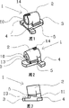
Fig. 1 illustrates the back and the side of electric wire connecting junction of the present invention;
Fig. 2 illustrates the front and the side of electric wire connecting junction of the present invention;
Fig. 3 illustrates the end view of electric wire connecting junction of the present invention;
Fig. 4 illustrates being used on the circuit board and accepts the profile of the through hole of electric wire connecting junction of the present invention;
Fig. 5 illustrates the bottom view of circuit board, and wherein, electric wire connecting junction of the present invention is inserted in the above-mentioned through hole;
Fig. 6 illustrates the bottom view of circuit board, and wherein, electric wire connecting junction of the present invention is in locked position;
Fig. 7 illustrates the end view that is positioned at the electric wire connecting junction of the present invention on the circuit board;
Fig. 8 illustrates the perspective view that is positioned at the electric wire connecting junction on the circuit board of Fig. 7;
Fig. 9 illustrates the top view that is positioned at the electric wire connecting junction on the circuit board of Fig. 7.
Embodiment
Fig. 1~3 illustrate the close-up view of seeing from 3 different angles of electric wire connecting junction 1 of the present invention.Described electric wire connecting junction 1 has a through hole 10 that is used to admit cable end that extends through connector housing 2, and during assembling, cable armouring is electrically connected with connector housing 2 by the method that it is welded in the groove 14.Connector housing 2 has respectively from its side and two upper lip 5 and a lower lips 3 of stretching out previously.(see Fig. 7~9) when electric wire connecting junction 1 is fixed on the circuit board, above-mentioned upper and lower lip 5,3 is in the upside and the downside of circuit board respectively.Have between the upper and lower lip be used for circuit board on the recess 11,13 that accurately cooperates of the edge of narrow groove 6 so that electric wire connecting junction 1 is clamped on the circuit board, and prevent its vertically mobile by upper and lower lip 5,3.
In the embodiment shown, between upper lip 5 and the lower lips 3 certain fore-and-aft distance is arranged.But upper lip 5 also can place lower lips 3 tops, so is directly separated by recess 11 between them.
Recess 11 can make electric wire connecting junction longitudinally slip in the narrow groove 6 of circuit board, extends the expanded range as narrow groove 6.The width limitations of narrow groove 6 being displaced sideways of electric wire connecting junction 1.According to the present invention, electric wire connecting junction 1 also have two from housing extend laterally press locating piece 4, the height of this locating piece 4 roughly height with lower lips 3 is identical.When it being placed in its final latched position, locating piece 4 is fixed on electric wire connecting junction 1 on the position suitable on the circuit board with upper and lower lip 5,3.When electric wire connecting junction inserted the narrow groove 6 of circuit board, the above-mentioned locating piece 4 that presses can force circuit board to be bent upwards slightly, and when electric wire connecting junction was pushed into its final position forward, locating piece 4 snapped in the corresponding hole 7 of passing circuit board, and these holes 7 are as lock portion.The front surface 13 of above-mentioned recess 11 can stop electric wire connecting junction further to front slide, press locating piece 4 then the prevention electric wire connecting junction slide backward.
Can more be clear that the situation that engages of electric wire connecting junction 1 and locking hole 7 from Fig. 4~6.Fig. 4 illustrates the narrow groove on the circuit board and the profile of locking hole 7.Narrow groove 6 can be admitted lower lips 3, and has and be used to admit the lateral elongation section 6a that presses locating piece 4,6b.Fig. 5 illustrates the narrow groove 6 of looking from the bottom surface of circuit board, has inserted in the narrow groove for electric wire connecting junction shown in the figure, but has not been pushed into locked position.In Fig. 6, the electric wire connecting junction that inserts in the narrow groove has been pushed into its locked position, at this moment, presses locating piece 4 and engages with hole 7, and the front surface of recess 11 leans against on the inward flange of narrow groove 6.Above-mentioned hole 7 and narrow groove 6 can come out with the bit drills of two kinds of different-diameters, and perhaps, but also milling is come out.
Fig. 7~9 illustrate the electric wire connecting junction that is in the locked position on the circuit board from 3 different angles, wherein, cable 12 are housed in the electric wire connecting junction.Electric wire connecting junction 1 is fixed on the appropriate location by engaging with the gap of minimum with narrow groove 6 and hole 7.The inner wire 8 of cable to the previous dynasty micro belt conductor 9 extend, and by electric wire connecting junction 1 stationary positioned.Cable armouring directly is electrically connected with the electric wire connecting junction of conduction, therefore also is electrically connected with lower lips 3.The inner wire 8 of cable can be soldered on the micro belt conductor 9, lower lips 3 and press locating piece 4 and can be welded on the ground plane of circuit board bottom surface.If electric wire connecting junction for example be subjected to owing to cable by the effect of the power that produces along the pulling of leaving the direction of circuit board, above-mentioned weld seam can not be subjected to mechanical stress.Above-mentioned power can be born by circuit board itself.
As shown in Figure 8, the insulating core 15 of cable (being made by the teflon plastics) stretches out outside the through hole 10 slightly, to keep the fixed insulation distance between cable armouring and the inner wire.
In Fig. 4~6 and 8~9, narrow groove 6 is as a through hole that is roughly T shape on circuit board, and locking hole 7 similarly is the manhole on the circuit board, still, other different shapes also can be made in these holes, as long as electric wire connecting junction can be admitted, fix and be locked on the circuit board.Such alternative embodiment is directly to stretch out narrow groove 6 from the flattened edge of circuit board, and wherein, narrow groove does not have wider portion 6a, 6b (transverse part on " T " font).
As shown in Figure 5, when electric wire connecting junction inserted circuit board from top, above-mentioned wider portion 6a, 6b admitted electric wire connecting junction.Locking hole 7 also can be made groove rather than through hole, and they can extend out rather than isolated from narrow groove 6, perhaps they is made and can stretch into slightly and the above-mentioned pallet shape that presses in the narrow groove 6 that locating piece 4 matches.
The advantage that adopts the electric wire connecting junction of conduction of the present invention is the surface that electric wire connecting junction has bigger derivation earth current, that is to say and in the mode of the low fine qualification of current density earth current to be conducted to the ground plane of circuit board from cable armouring by electric wire connecting junction, so just can obtain low intermodulation effect.Can be easily flow to lower lips from the high frequency earthing electric current of cable armouring from the whole periphery of armouring.Height when another advantage of the foregoing description is its assembling is low.
Electric wire connecting junction of the present invention for example can adopt zinc or the casting of other metal or alloy to form.The electric wire connecting junction surface adds that the coating of copper for example and silver can further improve its electrical property and especially reduces its cross modulation level.

Claims (10)

1.一种接线器(1),用于接纳电缆端部(12)并可安置成固定到电路板上,所述接线器(1)包括:1. A connector (1) for receiving a cable end (12) and capable of being fixed to a circuit board, said connector (1) comprising: 一个用于接纳上述电缆端部的通孔(10);a through hole (10) for receiving the end of said cable; 至少一个上唇部(5)和至少一个下唇部(3),在该上、下唇部之间形成与上述电路板上的窄槽(6)的边缘相配合的接线器凹部(11,13);At least one upper lip (5) and at least one lower lip (3), between which are formed connector recesses (11, 13) which cooperate with the edges of the narrow groove (6) on the above-mentioned circuit board ); 其特征在于,It is characterized in that, 上述接线器还具有至少一个设置在上述凹部(11,13)附近的紧压定位块(4),用于与电路板上的邻近上述窄槽(6)边缘的部位(7)相接合。The above-mentioned connector also has at least one pressing positioning block (4) arranged near the above-mentioned recess (11, 13) for engaging with the part (7) on the circuit board adjacent to the edge of the above-mentioned narrow slot (6). 2.根据权利要求1的接线器,其特征在于,上述接线器凹部(11,13)做成可沿大致平行于上述通孔(10)的中心轴线的纵长方向接纳上述窄槽边缘,上述凹部(11)具有靠着上述边缘的前表面(13)。2. The connector according to claim 1, characterized in that, said connector recess (11, 13) is made to receive said narrow groove edge along a longitudinal direction substantially parallel to the central axis of said through hole (10), said The recess (11) has a front surface (13) abutting against said edge. 3.根据权利要求1或2的接线器,其特征在于,上述的紧压定位块(4)可与上述部位(7)锁紧接合,这就可防止上述接线器沿上述凹部连接上述窄槽边缘的方向移动。3. The connector according to claim 1 or 2, characterized in that the above-mentioned pressing positioning block (4) can be locked and engaged with the above-mentioned part (7), which can prevent the above-mentioned connector from connecting with the above-mentioned narrow groove along the above-mentioned recess direction of the edge to move. 4.根据权利要求1~3的任一项的接线器,其特征在于,上述通孔(10)的内表面与上述的上、下唇部(5,3)电连接。4. The connector according to any one of claims 1-3, characterized in that the inner surface of the above-mentioned through hole (10) is electrically connected with the above-mentioned upper and lower lips (5, 3). 5.根据权利要求4的接线器,其特征在于,上述的下唇部(3)适合于与上述电路板底面的接地平面电连接。5. The connector according to claim 4, characterized in that said lower lip (3) is adapted to be electrically connected to a ground plane on the bottom surface of said circuit board. 6.根据权利要求1~5中任一项的接线器,其特征在于,上述的紧压定位块4设置在上述接线器凹部(11,13)的下侧。6. The connector according to any one of claims 1-5, characterized in that, the pressing positioning block 4 is arranged on the lower side of the concave part (11, 13) of the connector. 7.根据权利要求1~6中任一项的接线器,其特征在于,它具有两个从侧向向外伸出的紧压定位块(4)。7. The connector according to any one of claims 1-6, characterized in that it has two pressing positioning blocks (4) projecting outward from the side. 8.根据权利要求1~7中任一项的接线器,其特征在于,上述的每个紧压定位块(4)可与构成上述电路板的一个部位的凹槽(7)相配合。8. The connector according to any one of claims 1-7, characterized in that, each of the pressing positioning blocks (4) can cooperate with a groove (7) forming a part of the above-mentioned circuit board. 9.根据权利要求1~8中任一项的接线器,其特征在于,上述的紧压定位块(4)与上、下唇部(5,3)沿纵向彼此隔开。9. The connector according to any one of claims 1-8, characterized in that the above-mentioned pressing positioning block (4) and the upper and lower lips (5, 3) are spaced apart from each other in the longitudinal direction. 10.电路板与权利要求1~9中任一项的接线器的组合件,其特征在于,上述的电路板上的窄槽(6)是一种大致为T形的孔(6a,6b)。10. The assembly of the circuit board and the connector according to any one of claims 1 to 9, characterized in that the narrow groove (6) on the above-mentioned circuit board is a substantially T-shaped hole (6a, 6b) .
CNB028080971A 2001-04-11 2002-02-13 circuit board connector Expired - Fee Related CN1285144C (en)

Applications Claiming Priority (2)

Application Number Priority Date Filing Date Title
SE0101303A SE520321C2 (en) 2001-04-11 2001-04-11 PCB plug
SE01013036 2001-04-11

Publications (2)

Publication Number Publication Date
CN1502148A true CN1502148A (en) 2004-06-02
CN1285144C CN1285144C (en) 2006-11-15

Family

ID=20283767

Family Applications (1)

Application Number Title Priority Date Filing Date
CNB028080971A Expired - Fee Related CN1285144C (en) 2001-04-11 2002-02-13 circuit board connector

Country Status (8)

Country Link
US (1) US7008265B2 (en)
EP (1) EP1378025B1 (en)
CN (1) CN1285144C (en)
AT (1) ATE455378T1 (en)
DE (1) DE60235072D1 (en)
ES (1) ES2335975T3 (en)
SE (1) SE520321C2 (en)
WO (1) WO2002084808A1 (en)

Cited By (3)

* Cited by examiner, † Cited by third party
Publication number Priority date Publication date Assignee Title
CN100590934C (en) * 2006-05-31 2010-02-17 台达电子工业股份有限公司 Terminal structure and connecting method thereof
CN102437412A (en) * 2010-05-10 2012-05-02 泰科电子公司 Wireless communication system
CN111342249A (en) * 2018-12-19 2020-06-26 康普技术有限责任公司 Connector for coaxial cable

Families Citing this family (17)

* Cited by examiner, † Cited by third party
Publication number Priority date Publication date Assignee Title
FI20021331A0 (en) 2002-07-05 2002-07-05 Nokia Corp Procedure and arrangement for coupling
US20070054510A1 (en) * 2005-09-02 2007-03-08 Russell Price System and method for shielded coaxial cable attachment
JP2007305516A (en) * 2006-05-15 2007-11-22 Fujitsu Ltd Coaxial connector, connector assembly, printed circuit board, and electronic device
US20070257160A1 (en) * 2006-05-08 2007-11-08 M/A-Com, Inc. Cable attaching clamp
FR2942569B1 (en) * 2009-02-25 2011-03-25 Alcatel Lucent CONNECTING DEVICE FOR A COAXIAL CABLE CARRYING HIGH FREQUENCY SIGNAL.
DE102009046870B4 (en) * 2009-11-19 2017-05-24 Ifm Electronic Gmbh Electronic switching device with connection cable
TW201216568A (en) * 2010-10-08 2012-04-16 Univ Nat Taipei Technology Connector
KR101177866B1 (en) * 2011-03-24 2012-08-28 주식회사 케이엠더블유 Contact device for coxial rf cable
JP6056649B2 (en) * 2013-05-15 2017-01-11 日立金属株式会社 Termination structure, termination method and termination terminal of high-speed transmission line
EP2882039A1 (en) * 2013-12-05 2015-06-10 Alcatel-Lucent Shanghai Bell Co., Ltd. Coaxial cable to non-solderable material transition
CN103647127B (en) * 2013-12-09 2017-02-01 上海贝尔股份有限公司 Connector used for coupling coaxial cable to strip line
JP2016127008A (en) * 2014-12-26 2016-07-11 日本電業工作株式会社 Coaxial cable coupling member, communication circuit, and communication device
WO2016104586A1 (en) * 2014-12-26 2016-06-30 日本電業工作株式会社 Coaxial cable coupling member, communication circuit, and communication device
US12068520B2 (en) * 2019-07-03 2024-08-20 Kabushiki Kaisha Toshiba Coaxial microstrip line conversion circuit
DE102021122329A1 (en) 2021-08-30 2023-03-02 Md Elektronik Gmbh Connector and method of connecting a printed circuit board to at least one conductor
DE102021123830A1 (en) 2021-09-15 2023-03-16 Md Elektronik Gmbh Soldering aid, assembly and method for fixing a stranded wire on a contact area of a printed circuit board
USD1036385S1 (en) * 2021-09-17 2024-07-23 Coilcraft, Incorporated Electronic component

Family Cites Families (10)

* Cited by examiner, † Cited by third party
Publication number Priority date Publication date Assignee Title
US3201721A (en) * 1963-12-30 1965-08-17 Western Electric Co Coaxial line to strip line connector
US4401356A (en) * 1980-11-24 1983-08-30 C. R. Bard, Inc. Electrical terminal
JPH0353426Y2 (en) * 1986-03-15 1991-11-21
FR2720196B1 (en) * 1994-05-19 1996-06-21 Thomson Csf Connection device for ensuring a cable connection on a printed circuit and printed circuit equipped with such a device.
US5667390A (en) * 1995-03-06 1997-09-16 Hon Hai Precision Ind. Co., Ltd. I/O card and its associated cable harness assembly
US5755586A (en) * 1995-06-07 1998-05-26 Maxtor Corporation PCMCIA strain relieved electrical connector assembly
DE59712744D1 (en) * 1996-12-13 2006-11-23 Fuba Automotive Gmbh Line connector
US6575762B2 (en) * 2001-09-17 2003-06-10 Fci Americas Technology, Inc. Connection of coaxial cable to a circuit board
US6804122B1 (en) * 2003-08-12 2004-10-12 Yazaki North America, Inc. Self-stabilizing card edge terminal
US6932659B1 (en) * 2004-01-14 2005-08-23 Yazaki North America, Inc. Terminal with card edge locking provisions

Cited By (3)

* Cited by examiner, † Cited by third party
Publication number Priority date Publication date Assignee Title
CN100590934C (en) * 2006-05-31 2010-02-17 台达电子工业股份有限公司 Terminal structure and connecting method thereof
CN102437412A (en) * 2010-05-10 2012-05-02 泰科电子公司 Wireless communication system
CN111342249A (en) * 2018-12-19 2020-06-26 康普技术有限责任公司 Connector for coaxial cable

Also Published As

Publication number Publication date
US7008265B2 (en) 2006-03-07
SE0101303L (en) 2002-10-12
EP1378025A1 (en) 2004-01-07
ATE455378T1 (en) 2010-01-15
US20040171301A1 (en) 2004-09-02
SE0101303D0 (en) 2001-04-11
HK1066103A1 (en) 2005-03-11
CN1285144C (en) 2006-11-15
EP1378025B1 (en) 2010-01-13
WO2002084808A1 (en) 2002-10-24
DE60235072D1 (en) 2010-03-04
SE520321C2 (en) 2003-06-24
ES2335975T3 (en) 2010-04-07

Similar Documents

Publication Publication Date Title
CN1502148A (en) circuit board connector
EP2434581B1 (en) Electrical connector
CN2596597Y (en) Electric connector
US5741161A (en) Electrical connection system with discrete wire interconnections
US11145995B2 (en) Electrical contact element and method of producing a hard-soldered, electrically conductive connection to a mating contact by means of a pressed-in soldering body made from hard solder
CN1308393A (en) Manufacture of socket connector
US8858254B2 (en) Electric connector and manufacturing method thereof
CN1283886A (en) Cable connector and its making method
CN1169603A (en) Electrical connector having terminals with improved retention means
KR100216615B1 (en) Right-angle board to board connector with anti-wicking characteristics and terminal for same
CN1132268C (en) Electrical connector of pin grid array assembly
KR970702596A (en) Low Profile Electrical Connector
CN104054217A (en) Electrical connection device for producing solder connection and method for production thereof
WO2015105680A1 (en) Electrical connector having compliant contacts and a circuit board assembly including the same
US10985481B2 (en) Electric contacting device
CN1267935A (en) Electrical connector assembly
EP4089858A1 (en) Crimp contact, crimp connection and method for making a crimp connection
CN107431284A (en) Connector
CN1348621A (en) Electrical connector
CN1161863C (en) Shielded board mounted electrical connector
CN1040485C (en) Connection terminal with a variable thickness bracket and a crimped nut
US20250081352A1 (en) Filter component and method for producing a filter component
JP2023153751A (en) Spring clip header for flat flexible cable
CN1047880C (en) Press-connecting terminal
CN1242513C (en) Low-profile connector

Legal Events

Date Code Title Description
C06 Publication
PB01 Publication
C10 Entry into substantive examination
SE01 Entry into force of request for substantive examination
REG Reference to a national code

Ref country code: HK

Ref legal event code: DE

Ref document number: 1066103

Country of ref document: HK

C14 Grant of patent or utility model
GR01 Patent grant
C41 Transfer of patent application or patent right or utility model
C56 Change in the name or address of the patentee
CP01 Change in the name or title of a patent holder

Address after: Swedish tibbers

Patentee after: Power wave Sweden

Address before: Swedish tibbers

Patentee before: Allgon AB

TR01 Transfer of patent right

Effective date of registration: 20160802

Address after: California, USA

Patentee after: INTEL Corp.

Address before: Luxemburg Luxemburg

Patentee before: POWERWAVE TECHNOLOGIES, Inc.

Effective date of registration: 20160802

Address after: Luxemburg Luxemburg

Patentee after: POWERWAVE TECHNOLOGIES, Inc.

Address before: California, USA

Patentee before: P-wave holding LLC

Effective date of registration: 20160802

Address after: California, USA

Patentee after: P-wave holding LLC

Address before: California, USA

Patentee before: POWERWAVE TECHNOLOGIES, Inc.

Effective date of registration: 20160802

Address after: California, USA

Patentee after: POWERWAVE TECHNOLOGIES, Inc.

Address before: Sweden xisita

Patentee before: POWERWAVE TECHNOLOGIES SWEDEN AB

Effective date of registration: 20160802

Address after: Sweden xisita

Patentee after: POWERWAVE TECHNOLOGIES SWEDEN AB

Address before: Swedish tibbers

Patentee before: Power wave Sweden

CF01 Termination of patent right due to non-payment of annual fee

Granted publication date: 20061115

Termination date: 20180213