Background technology
Different with railway network between the area of carrying out the electric power transmission by the catenary system on the crown, and the electric power of subway (subway line) or urban light rail line transmission normally passing through conductor rail.Such conductor rail can be the track form that for example is installed in the guide rail side.So can conductor rail be set like this, make current colector from following, from side or from top and conductor rail moving contact.
When the railway system of above-mentioned conductor rail carries out the work of any kind, not only to interrupt the electric power supply of conductor rail but also safety device will be installed as safety measure, be so-called short circuit device, its short circuit is as the conductor of positive pole with as the track of negative pole--normally guide rail one of them.By this way, short circuit mechanism is also referred to as the ground short circuit facility, cause electrically conductive to connect so that guide current is left when taking place to handle mistake, thereby protection relates to the your life of accident.
Therefore before the work place and above-mentioned short circuit device is installed afterwards so that protection work place and prevent the flowing of short circuit current on all sides.
The short circuit device of using is made up of two arms at present, two arms link together by the joint of hinge type, therefore the first arm constitutes contact arm, at the operating position contact arm is level, and contact with conductor rail as contact finger, with second arm constitute base arm the operating position base arm be vertical with the boots that contact that are parked on the guide rail are arranged.Contact arm is pressed on the conductor rail by tension spring at operating position, the tension spring hinge vertically is added on the conductor rail to base arm with pulling force.
A shortcoming of present short circuit device is that their short circuit impedance is too low.The short circuit impedance of general present short circuit device is about 30kA afterwards at 23ms break time (millisecond).But the scope of electrical equipment usually is according to the short circuit that level 50 to 60kA is arranged in the railway system.
Short circuit device, it will stand very big electric current when being short-circuited, and is normally destroyed or is badly damaged at least.Its reason be the cross-sectional plane of conductor always underestimated and work as the electric current that flows through when too big conducting element by heat damage.Also have, the design-calculated circuit breaker normally is to launch away at present, because the situation that has the danger of hurting sb.'s feelings to launch is undesirable.
Summary of the invention
Therefore the objective of the invention is to propose a kind of short circuit device, it can be directed away the electric current of bigger level and not be damaged as far as possible when being short-circuited and do not launch away on the one hand.
Reached that purpose by the present invention, because articulated link mechanism is many articulated link mechanisms that two bars are arranged among the present invention, two bars interconnect with the flexure type joint, with by first and second being connected hinge and being connected to contact member and contact arm separately, therefore bar form that is closed bar and each bar and hinged shape and arrangement are like this, by rotate with closed bar with by of this motion of flexure type hinge around the axle that is connected hinge, electrically contact thereby contact member and contact arm can be lumped together to cause.
Usually, by the rotation that contact member and contact arm is lumped together closed bar first and second distances that connect between the hinges are reduced.
Many hinges connect and comprise by first and connect hinge and contact member bonded assembly closure bar in the preferred scheme of the present invention, and are connected hinge and contact arm bonded assembly pipe link by second, so by the flexure type hinge two bars are connected to each other.
Connect but also can design many hinges like this, it is comprised by connecting hinge and contact arm bonded assembly closure bar, and be connected hinge and contact member bonded assembly pipe link by another and two bars be connected to each other by the flexure type hinge.
Short circuit device preferably can be attached to guide rail by first and second jaws, therefore the many hinges of design connect like this, in order between contact member and contact arm, to electrically contact, thereby short circuit device can be clipped in the distance that reduces on the guide rail between first and second jaws tightly.So the effect of jaw such as a kind of fixing device and be attached on the guide rail.
First jaw preferably contact member a part and towards second jaw of first jaw part of contact arm preferably.The parts that second jaw is mounted in the contact arm terminal part in preferred version of the present invention particularly meet at right angles towards guide rail at angle basically.
The contact surface of two jaws is preferably located in the exterior boundary of guide rail, thereby makes jaw be fit to guide rail and the clamping effect that applies the best as far as possible when installing short circuit device.Also have, make jaw the most closely be assembled to the cross-sectional area that guide rail will increase area of contact and use conductor as far as possible as far as possible.
Electrically contacting preferably between guide rail and short circuit device only undertaken by contact member, promptly passes through first jaw of contact member.Therefore contact member or jaw are made and are conducted electricity, thus from the guide rail to the contact arm or the conductive connection of conductor rail preferably only undertaken by contact member.When guide rail being contacted when reclining, second jaw of contact arm does not advantageously carry out anyly electrically contacting with guide rail.Second jaw usefully is part or all of electric insulating.
The principle that the effect of many articulated link mechanisms is preferably locked according to known tension force is as people see from the fastener of clasp or belt-type.
So many articulated link mechanisms of design advantageously make electrically contacting between contact member and the contact arm enter into from suppressing the position by the rotation lock bar and obtain.Prevent to open and electrically contact from suppressing the position by self.
By the flexure type hinge closed bar and pipe link are linked together by this way and obtain self-inhibiting effect, in order to electrically contact, can make closed bar rotate and move around first axle that connects hinge, up to arriving the dead point, the feature at dead point is the shortest in first and second distances that connect between the hinge, with in order to cause the self-inhibiting effect of closed bar, it is rotated further above the dead point enters into terminal location.Therefore, the flexure type hinge with closed bar, has been finished around the rotation of the relevant first connection hinge.Connect distance between the hinges first and second and can obtain to close fast or swing and enter from suppressing terminal location by slightly enlarging, so in general the elasticity of synergistic element is also brought into play certain effect.
Suppressing the how hinged effect in position certainly as the close mechanism under at tension force, to have only by the rotation in the opposite direction of closed bar, the principle of using elbow response knee can discharge this close mechanism again.
Can be pressed at the closed position bar on the slipper of contact member, this moment, closed bar was to suppress the position certainly.Also have, also be appreciated that to provide closed bar is remained on from the measure that suppresses the position.In addition, many hinges connect also can have tension spring.
Contact arm comprises the contact arm housing of electric insulating in preferred scheme, arranges conducting element-so-called electric power conveying element in housing.The electric power conveying element further is connected to the contact surface of exposure so that provide and the electrically contacting of conductor rail.Contact member preferably includes travelling arm in this scheme, and at least a portion of arm is installed in the non-conductive contact arm housing, moves it in the mode of sliding there or guides it.In order to electrically contact, start the closed bar in the contact arm housing, along the direction promotion contact member and its travelling arm of electric power conveying element, run into the such formation of electric power conveying element up to travelling arm and electrically contact.
The electric power conveying element of contact arm is preferably the shape section, particularly the hollow material section.The electric power conveying element of contact arm can be the metal segments of extruding.Metal segments is the form of rectangular section in preferred scheme.The electric power conveying element can be, for example iron, steel, copper and particularly aluminum or aluminum alloy.
Can determine the cross-sectional area of metal segments according to the current value of expectation, therefore might make according to short circuit device of the present invention mechanically with electric on withstand all levels of current that can expect that short circuit causes, if promptly produce short circuit, use the size of definite suitably electric power conveying element, can stand to surpass the electric current of 200KA and can not suffer damage according to short circuit device of the present invention.
In preferred scheme, contact member is made up of first jaw and connected travelling arm basically.Therefore jaw and travelling arm preferably all conduct electricity, and are not that the assembly on each face of contact surface can partly or entirely cover with electric insulating.
Many hinges connections are the structures support shape in preferred scheme.It is characterized in that installing closed bar in the both sides of short circuit device; These bars are connected to support by Connection Element, and it constitutes one type handle.
Second hinge connection of contact arm preferably is installed on the contact arm housing.It can be the axle bonded assembly form of passing contact member that first hinge of contact member connects.
In its zone of anodal contact surface and/or in the zone of negative pole contact surface at it, short circuit device also can have magnet, and magnet provides the binding force of area of contact to the corresponding plus or minus utmost point.
Also have, short circuit device can be used electrically insulating material clad, preferably plastics except contact area.
For short circuit device is installed, this jaw that refers to by it is installed on the guide rail and since its weight contact arm be towards terrain slope therefore it can not contact with conductor rail.In next step, guide closed bar, make it to electrically contact with it thereby contact member and its travelling arm in the contact arm housing be pressed onto on the electric power conveying element by the rotation that is directed downwards along guide rail.Simultaneously first jaw of contact member is pressed onto second jaw of contact arm, thereby by this way guide rail is clipped between the jaw, electrically contact so that the rise contact arm contacts with conductor rail just can cause with the contact surface that makes it.
If closed bar is put into from suppressing the position, will be kept the formed contact surface of short circuit device needn't take any other measure so.Short circuit device according to above-mentioned special scheme can obtain to use in electric power supply system, and the moving contact with conductor rail in this system is to carry out below.
Because according to the different designs of short circuit device of the present invention, it has many-sided security consideration, prevent when its installation because mistake makes operator's accident ground contact with the element that carries electric current.Electric current only can flow between guide rail and conductor rail by first jaw of contact member on the one hand.First jaw just can conduction current when the both contacts between contact member and the contact arm and between contact arm and the conductor rail but have only.This is such situation, only after the closed bar of starting, has promptly all installed short circuit device, and closed bar is to suppress the position certainly and no longer needing further to handle the situation of short circuit device.
Because when mounted, all do not electrically contacting between contact member and the contact arm and between contact arm and conductor rail, so each element of guide rail and short circuit device does not all have conduction current when mounted.
Also can be designed for the short circuit device of such electric power supply system, in this system current collector be the side of conductor rail or above and conductor rail carry out moving contact.
Also be suitable as the handheld devices of daily use according to short circuit device of the present invention.For example, can be the short circuit device that carries by the railroader, in order in case of emergency on purpose to produce short circuit.When lay man stand in railway system's electric apparatus the zone in the time can be this situation.
The specific embodiment
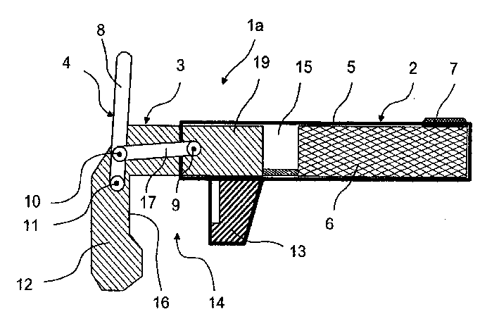
Fig. 1 represents the scheme drawing according to short circuit device 1a of the present invention.Short circuit device 1a comprises contact arm 2 and contact member 3, and they connect 4 by many hinges and connect.Contact arm comprises the contact arm housing 5 and the electric power transport element 6 of electric insulating, and this element enters into the contact arm housing and is connected to the contact surface 7 of conductor rail (not shown).Contact member 3 has contact surface 16 to guide rail for the form of conductive component.The feature of contact member 3 is first jaw 12 and the travelling arm 19 that is connected to first jaw.What be positioned at first jaw, 12 opposites is second jaw 13, and it is the part of contact arm 3 parts.Second jaw 13 is non-conductives, so feature is the contact zone that does not have conduction.Arrange two jaws 12,13 in the mode of hawkbill sample, constitute gap 14, when short circuit device installs, the guide rail (not shown) is placed in this gap.
Two jaws 12,13 have the profile of clip, and are complementary with the profile of guide rail.
Polylinker connects 4 and comprises closed bar 8, and it is connected to contact member 3 by first jointing 11.Also have, polylinker connects 4 and comprises pipe link 17, and it is connected to contact arm 2 by second jointing 9.Pipe link 17 is connected to the contact arm housing 5 of contact arm 2 in this example.Closed bar 8 and pipe link 17 also are connected to each other by flexure type joint 10.Therefore be that the flexure type joint is set like this, when closed bar 8 rotates and flexure type joint 10 centers on the axle motion of first jointing 11 thus, make the distance between first and second joints 11,9 reduce to make simultaneously the electric power conveying element 6 of contact member 3 and contact arm to contact.
Because this process diminishes gap 14, short circuit device 1 is clamped on the guide rail by it simultaneously as a result.Therefore, not only between the electric power conveying element 6 of contact member 3 and contact arm 2, electrically contact, and between the contact surface 16 of contact member 3 and guide rail, also produce and electrically contact.Two-fold safety is guaranteed in this two-fold contact.
Also have, by short circuit device is clamped on the guide rail, the bevelled contact arm 2 that does not have to support vertically lifts and makes contact surface 7 to be pressed onto the downside of conductor rail towards the front end of conductor rail, causes with conductor rail to contact.
Fig. 1 and 3 is illustrated in each assembling stage 1a, the 1b of short circuit device, the principle that the 1c short circuit device electrically contacts conductor rail and guide rail.
Short circuit device 1a is set on the guide rail, forms gap 14 by jaw 12,13.Then, rotate closed bar 8 around the axle that connects hinge 11 and leave contact arm 2 (Fig. 2).Making closed bar 8 surpass the dead point is parked in from suppressing the position.In this position, normally usefully rest on the contact arm 3 by through rod 8.
In this process, carry out three things.At first, the travelling arm 19 of contact member is pressed in the contact arm housing 5 of contact arm, the result along with distance 15 reduce between the electric power conveying element 6 of contact member 3 and contact arm 2, produce contact 18.Secondly, guide rail is led by two jaws 12,13 be clamped in the gap 14 and the 3rd solidly, vertically lift contact arm 2 by guide rail being clamped between the jaw 12,13, contact surface 7 abuts in to produce on the conductor rail and electrically contacts as a result.