CN1526053A - fuel delivery system - Google Patents
fuel delivery system Download PDFInfo
- Publication number
- CN1526053A CN1526053A CNA028111389A CN02811138A CN1526053A CN 1526053 A CN1526053 A CN 1526053A CN A028111389 A CNA028111389 A CN A028111389A CN 02811138 A CN02811138 A CN 02811138A CN 1526053 A CN1526053 A CN 1526053A
- Authority
- CN
- China
- Prior art keywords
- fuel
- air
- waste gas
- passage
- sparger
- Prior art date
- Legal status (The legal status is an assumption and is not a legal conclusion. Google has not performed a legal analysis and makes no representation as to the accuracy of the status listed.)
- Pending
Links
Images







Classifications
-
- F—MECHANICAL ENGINEERING; LIGHTING; HEATING; WEAPONS; BLASTING
- F01—MACHINES OR ENGINES IN GENERAL; ENGINE PLANTS IN GENERAL; STEAM ENGINES
- F01N—GAS-FLOW SILENCERS OR EXHAUST APPARATUS FOR MACHINES OR ENGINES IN GENERAL; GAS-FLOW SILENCERS OR EXHAUST APPARATUS FOR INTERNAL-COMBUSTION ENGINES
- F01N5/00—Exhaust or silencing apparatus combined or associated with devices profiting by exhaust energy
- F01N5/02—Exhaust or silencing apparatus combined or associated with devices profiting by exhaust energy the devices using heat
-
- F—MECHANICAL ENGINEERING; LIGHTING; HEATING; WEAPONS; BLASTING
- F02—COMBUSTION ENGINES; HOT-GAS OR COMBUSTION-PRODUCT ENGINE PLANTS
- F02B—INTERNAL-COMBUSTION PISTON ENGINES; COMBUSTION ENGINES IN GENERAL
- F02B75/00—Other engines
- F02B75/16—Engines characterised by number of cylinders, e.g. single-cylinder engines
- F02B75/18—Multi-cylinder engines
- F02B75/20—Multi-cylinder engines with cylinders all in one line
-
- F—MECHANICAL ENGINEERING; LIGHTING; HEATING; WEAPONS; BLASTING
- F02—COMBUSTION ENGINES; HOT-GAS OR COMBUSTION-PRODUCT ENGINE PLANTS
- F02M—SUPPLYING COMBUSTION ENGINES IN GENERAL WITH COMBUSTIBLE MIXTURES OR CONSTITUENTS THEREOF
- F02M31/00—Apparatus for thermally treating combustion-air, fuel, or fuel-air mixture
- F02M31/02—Apparatus for thermally treating combustion-air, fuel, or fuel-air mixture for heating
- F02M31/04—Apparatus for thermally treating combustion-air, fuel, or fuel-air mixture for heating combustion-air or fuel-air mixture
- F02M31/06—Apparatus for thermally treating combustion-air, fuel, or fuel-air mixture for heating combustion-air or fuel-air mixture by hot gases, e.g. by mixing cold and hot air
- F02M31/08—Apparatus for thermally treating combustion-air, fuel, or fuel-air mixture for heating combustion-air or fuel-air mixture by hot gases, e.g. by mixing cold and hot air the gases being exhaust gases
-
- F—MECHANICAL ENGINEERING; LIGHTING; HEATING; WEAPONS; BLASTING
- F02—COMBUSTION ENGINES; HOT-GAS OR COMBUSTION-PRODUCT ENGINE PLANTS
- F02M—SUPPLYING COMBUSTION ENGINES IN GENERAL WITH COMBUSTIBLE MIXTURES OR CONSTITUENTS THEREOF
- F02M31/00—Apparatus for thermally treating combustion-air, fuel, or fuel-air mixture
- F02M31/02—Apparatus for thermally treating combustion-air, fuel, or fuel-air mixture for heating
- F02M31/14—Apparatus for thermally treating combustion-air, fuel, or fuel-air mixture for heating by using heat from working cylinders or cylinder heads
-
- F—MECHANICAL ENGINEERING; LIGHTING; HEATING; WEAPONS; BLASTING
- F02—COMBUSTION ENGINES; HOT-GAS OR COMBUSTION-PRODUCT ENGINE PLANTS
- F02M—SUPPLYING COMBUSTION ENGINES IN GENERAL WITH COMBUSTIBLE MIXTURES OR CONSTITUENTS THEREOF
- F02M31/00—Apparatus for thermally treating combustion-air, fuel, or fuel-air mixture
- F02M31/02—Apparatus for thermally treating combustion-air, fuel, or fuel-air mixture for heating
- F02M31/16—Other apparatus for heating fuel
- F02M31/18—Other apparatus for heating fuel to vaporise fuel
-
- F—MECHANICAL ENGINEERING; LIGHTING; HEATING; WEAPONS; BLASTING
- F02—COMBUSTION ENGINES; HOT-GAS OR COMBUSTION-PRODUCT ENGINE PLANTS
- F02M—SUPPLYING COMBUSTION ENGINES IN GENERAL WITH COMBUSTIBLE MIXTURES OR CONSTITUENTS THEREOF
- F02M53/00—Fuel-injection apparatus characterised by having heating, cooling or thermally-insulating means
- F02M53/04—Injectors with heating, cooling, or thermally-insulating means
- F02M53/06—Injectors with heating, cooling, or thermally-insulating means with fuel-heating means, e.g. for vaporising
-
- F—MECHANICAL ENGINEERING; LIGHTING; HEATING; WEAPONS; BLASTING
- F01—MACHINES OR ENGINES IN GENERAL; ENGINE PLANTS IN GENERAL; STEAM ENGINES
- F01N—GAS-FLOW SILENCERS OR EXHAUST APPARATUS FOR MACHINES OR ENGINES IN GENERAL; GAS-FLOW SILENCERS OR EXHAUST APPARATUS FOR INTERNAL-COMBUSTION ENGINES
- F01N2240/00—Combination or association of two or more different exhaust treating devices, or of at least one such device with an auxiliary device, not covered by indexing codes F01N2230/00 or F01N2250/00, one of the devices being
- F01N2240/02—Combination or association of two or more different exhaust treating devices, or of at least one such device with an auxiliary device, not covered by indexing codes F01N2230/00 or F01N2250/00, one of the devices being a heat exchanger
-
- F—MECHANICAL ENGINEERING; LIGHTING; HEATING; WEAPONS; BLASTING
- F02—COMBUSTION ENGINES; HOT-GAS OR COMBUSTION-PRODUCT ENGINE PLANTS
- F02B—INTERNAL-COMBUSTION PISTON ENGINES; COMBUSTION ENGINES IN GENERAL
- F02B75/00—Other engines
- F02B75/16—Engines characterised by number of cylinders, e.g. single-cylinder engines
- F02B75/18—Multi-cylinder engines
- F02B2075/1804—Number of cylinders
- F02B2075/1824—Number of cylinders six
-
- F—MECHANICAL ENGINEERING; LIGHTING; HEATING; WEAPONS; BLASTING
- F02—COMBUSTION ENGINES; HOT-GAS OR COMBUSTION-PRODUCT ENGINE PLANTS
- F02M—SUPPLYING COMBUSTION ENGINES IN GENERAL WITH COMBUSTIBLE MIXTURES OR CONSTITUENTS THEREOF
- F02M61/00—Fuel-injectors not provided for in groups F02M39/00 - F02M57/00 or F02M67/00
- F02M61/16—Details not provided for in, or of interest apart from, the apparatus of groups F02M61/02 - F02M61/14
- F02M61/166—Selection of particular materials
-
- F—MECHANICAL ENGINEERING; LIGHTING; HEATING; WEAPONS; BLASTING
- F02—COMBUSTION ENGINES; HOT-GAS OR COMBUSTION-PRODUCT ENGINE PLANTS
- F02M—SUPPLYING COMBUSTION ENGINES IN GENERAL WITH COMBUSTIBLE MIXTURES OR CONSTITUENTS THEREOF
- F02M69/00—Low-pressure fuel-injection apparatus ; Apparatus with both continuous and intermittent injection; Apparatus injecting different types of fuel
- F02M69/04—Injectors peculiar thereto
- F02M69/042—Positioning of injectors with respect to engine, e.g. in the air intake conduit
- F02M69/044—Positioning of injectors with respect to engine, e.g. in the air intake conduit for injecting into the intake conduit downstream of an air throttle valve
-
- F—MECHANICAL ENGINEERING; LIGHTING; HEATING; WEAPONS; BLASTING
- F02—COMBUSTION ENGINES; HOT-GAS OR COMBUSTION-PRODUCT ENGINE PLANTS
- F02M—SUPPLYING COMBUSTION ENGINES IN GENERAL WITH COMBUSTIBLE MIXTURES OR CONSTITUENTS THEREOF
- F02M69/00—Low-pressure fuel-injection apparatus ; Apparatus with both continuous and intermittent injection; Apparatus injecting different types of fuel
- F02M69/04—Injectors peculiar thereto
- F02M69/042—Positioning of injectors with respect to engine, e.g. in the air intake conduit
- F02M69/045—Positioning of injectors with respect to engine, e.g. in the air intake conduit for injecting into the combustion chamber
-
- F—MECHANICAL ENGINEERING; LIGHTING; HEATING; WEAPONS; BLASTING
- F02—COMBUSTION ENGINES; HOT-GAS OR COMBUSTION-PRODUCT ENGINE PLANTS
- F02M—SUPPLYING COMBUSTION ENGINES IN GENERAL WITH COMBUSTIBLE MIXTURES OR CONSTITUENTS THEREOF
- F02M69/00—Low-pressure fuel-injection apparatus ; Apparatus with both continuous and intermittent injection; Apparatus injecting different types of fuel
- F02M69/46—Details, component parts or accessories not provided for in, or of interest apart from, the apparatus covered by groups F02M69/02 - F02M69/44
- F02M69/462—Arrangement of fuel conduits, e.g. with valves for maintaining pressure in the pipes after the engine being shut-down
- F02M69/465—Arrangement of fuel conduits, e.g. with valves for maintaining pressure in the pipes after the engine being shut-down of fuel rails
-
- Y—GENERAL TAGGING OF NEW TECHNOLOGICAL DEVELOPMENTS; GENERAL TAGGING OF CROSS-SECTIONAL TECHNOLOGIES SPANNING OVER SEVERAL SECTIONS OF THE IPC; TECHNICAL SUBJECTS COVERED BY FORMER USPC CROSS-REFERENCE ART COLLECTIONS [XRACs] AND DIGESTS
- Y02—TECHNOLOGIES OR APPLICATIONS FOR MITIGATION OR ADAPTATION AGAINST CLIMATE CHANGE
- Y02T—CLIMATE CHANGE MITIGATION TECHNOLOGIES RELATED TO TRANSPORTATION
- Y02T10/00—Road transport of goods or passengers
- Y02T10/10—Internal combustion engine [ICE] based vehicles
- Y02T10/12—Improving ICE efficiencies
Landscapes
- Engineering & Computer Science (AREA)
- Chemical & Material Sciences (AREA)
- Combustion & Propulsion (AREA)
- Mechanical Engineering (AREA)
- General Engineering & Computer Science (AREA)
- Fuel-Injection Apparatus (AREA)
- Cylinder Crankcases Of Internal Combustion Engines (AREA)
- Exhaust Gas After Treatment (AREA)
Abstract
Description
相关申请related application
本申请是以2001年6月1日申请的澳大利亚临时申请No.PR5397、2001年12月13日申请的澳大利亚临时申请No.PR9540、以及2001年7月19日申请的美国临时申请No.60/306606为基础,并要求享有上述申请的优先权。This application is based on Australian Provisional Application No.PR5397 filed on June 1, 2001, Australian Provisional Application No.PR9540 filed on December 13, 2001, and U.S. Provisional Application No.60/ 306606 and claims priority from the above application.
技术领域technical field
本发明涉及一种燃料输送系统,用于将石油或汽油燃料输送给内燃机,还涉及具有该输送系统的内燃机和车辆。The present invention relates to a fuel delivery system for delivering petroleum or gasoline fuel to an internal combustion engine, and to an internal combustion engine and a vehicle having such a delivery system.
发明背景Background of the invention
为提高车辆的燃料效率,人们已经进行了多次试验。但最近在此方面的进展是使得内燃机的设计更加复杂,其操作方式也更加复杂。Several experiments have been conducted to improve the fuel efficiency of vehicles. But recent advances in this area have made the design of internal combustion engines more complex and the way they operate.
按照惯例,由燃料和空气所构成的可燃混合物的最佳混合比为两者重量比14.7比1,此比例是按化学公式计算得到的。当在某给定转矩曲线下进行操作,能量与效率首次达到平衡时,就可获得在传统操作条件下能产生最佳喷射的比例。由于燃料的性质决定了燃料本身是一种低温物质,因而燃料在发动机的燃烧室内还起到冷却功能,以维持接触表面例如阀门及活塞的完整性。减少燃烧用燃料将导致燃烧室温度及废气温度升高,部件在此高温下将熔融,或者部件由于膨胀以及发动机内间距和配合间隙的减小而停止工作,从而导致发动机出现故障。Conventionally, the optimum mixing ratio of the combustible mixture composed of fuel and air is 14.7 to 1 by weight, which is calculated according to the chemical formula. When operating at a given torque curve, power and efficiency are first balanced to obtain the ratio that produces optimum injection under conventional operating conditions. Because the nature of the fuel determines that the fuel itself is a low-temperature substance, the fuel also acts as a cooling function in the combustion chamber of the engine to maintain the integrity of contacting surfaces such as valves and pistons. Reducing the fuel used for combustion will cause the temperature of the combustion chamber and the exhaust gas to rise. At this high temperature, the components will melt, or the components will stop working due to expansion and the reduction of internal spacing and fit clearance in the engine, resulting in engine failure.
人们已经试图通过在发动机的喷射器与气缸之间提供某种加热机构来提高燃料效率。这些系统的工作原理是:利用喷射器喷射液体状态的燃料,在喷射过程后且在将该燃料输送至发动机气缸之前,使该燃料气化。Attempts have been made to improve fuel efficiency by providing some kind of heating mechanism between the injectors and the cylinders of the engine. These systems work by injecting fuel in a liquid state with injectors, vaporizing the fuel after the injection process and before delivering the fuel to the cylinders of the engine.
发明概述Summary of the invention
本发明的目的是提供这样一种燃料输送系统,该系统可提高燃料效率,并易于作为现有发动机的一个附加部件,或者易于作为制造发动机的一个原始部件。It is an object of the present invention to provide a fuel delivery system which improves fuel efficiency and which is readily available as an add-on to existing engines, or as an original component in the manufacture of engines.
本发明的第一方面可认为在于一种用于内燃机的燃料输送系统,该内燃机具有至少一个气缸以及在该气缸内往复运动的活塞,该系统包括;A first aspect of the invention may be considered to reside in a fuel delivery system for an internal combustion engine having at least one cylinder and a piston reciprocating within the cylinder, the system comprising;
燃料喷射器,包括主体和端部区域,自该端部区域输送燃料以将燃料输送给气缸;a fuel injector comprising a body and an end region delivering fuel from the end region for delivering fuel to the cylinder;
燃料通道,延伸于燃料喷射器与气缸之间,以将燃料自输送件输送至气缸;以及a fuel passage extending between the fuel injector and the cylinder to deliver fuel from the delivery member to the cylinder; and
加热装置,对喷射器的端部区域进行加热,从而在该喷射器喷出该燃料之前,加热该端部区域内的燃料,这样当喷射器喷出燃料时,该燃料能转换为气态,同时在该燃料沿着燃料通道自喷射器行进至气缸的途中,可维持该燃料处于气态。heating means for heating the end region of the injector so as to heat the fuel in the end region before the injector ejects the fuel, so that when the injector ejects the fuel, the fuel can be converted into a gaseous state and at the same time The fuel may be maintained in a gaseous state as it travels along the fuel passage from the injector to the cylinder.
本发明人发现,加热燃料以使该燃料气化的传统技术是在燃料自喷射器喷出之后再加热该燃料。因此在现有技术中,所喷出的燃料是液态而不是气态,在喷射器的下游提供某种加热机构,以将该燃料转换为气态。由于燃料在发动机的抽吸作用下自喷射器行进至气缸所花费的时间较短,同时路径长度较短,因而该加热机构不能充分地起到将该液体燃料转换为气态的作用,所以这些系统的操作不能令人满意。因此,基于这个原理进行工作的系统还没有什么显著的商业应用。本发明人发现,加热喷射器的端部区域,并因而加热该喷射器那部分内的燃料,由于该喷射器内的压力恒定,该燃料在端部区域内将维持在液态,但一旦该燃料离开喷射器,由于该燃料离开喷嘴时压力减小,同时由于受热燃料的热膨胀,液态燃料将迅速地转化为蒸气。The inventors have discovered that the conventional technique of heating fuel to vaporize the fuel is to heat the fuel after it has been ejected from the injector. Thus in the prior art the injected fuel is in liquid rather than gaseous state and some kind of heating mechanism is provided downstream of the injector to convert the fuel into gaseous state. Due to the short time it takes for the fuel to travel from the injector to the cylinder under the pumping action of the engine, and the short path length, the heating mechanism does not function adequately to convert the liquid fuel to a gaseous state, so these systems operation is unsatisfactory. As a result, systems that work on this principle have had no significant commercial application. The inventors have found that by heating the end region of the injector, and thus heating the fuel in that part of the injector, the fuel will remain liquid in the end region due to the constant pressure in the injector, but once the fuel Leaving the injector, the liquid fuel will rapidly convert to vapor due to the pressure reduction of the fuel as it exits the nozzle and due to the thermal expansion of the heated fuel.
因此,当燃料离开喷射器时,该燃料通过喷射器处的闪蒸效应能迅速地由液态转换为气态。由此,全部燃料都将气化,并且在燃料自喷射器行进至发动机气缸的途中,维持该燃料处于气态。利用加热装置来维持该燃料蒸气处于气态,该加热装置在燃料蒸气离开喷射器时,向该燃料供应热量以维持蒸气状态。Therefore, when the fuel leaves the injector, the fuel is rapidly converted from a liquid state to a gaseous state by the flashing effect at the injector. Thus, all of the fuel will vaporize and maintain the fuel in a gaseous state as it travels from the injector to the cylinders of the engine. The fuel vapor is maintained in the gaseous state by means of a heating device which supplies heat to the fuel to maintain the vapor state as the fuel vapor exits the injector.
当蒸气沿着燃料通道行进时,该蒸气将向外膨胀到周围的气流中,该气流在燃料沿着通道长度行进的过程中能略微地冷却该燃料,但是,由于该燃料的热量以及该燃料分散到沿着燃料通道流动的气流中,因而将维持该燃料蒸气处于气态,这样就将蒸气状态的燃料输送给发动机气缸。换句话说,对喷射器内的燃料进行加热以在该燃料自端部区域喷出时产生闪蒸效应,并在较热的环境温度下维持该气态。燃料蒸气稀释到普通吸入空气中,可对该受热气体混合物进行冷却,但混合气体的温度仍然较高,因而可将蒸气状态的燃料输送给气缸。由于将燃料气化,并将蒸气状态的燃料输送给发动机气缸,因而发动机在保持所有部件完整性的同时,可以较贫的混合物进行操作,功率输出提高并改良了排放物,更重要的是,能防止在贫燃混合物下可能发生的温度过高,从而在维持发动机性能的同时,极大地减少所用燃料量。As the vapor travels down the fuel passage, the vapor will expand outward into the surrounding airflow, which can cool the fuel slightly as it travels along the length of the passage, however, due to the heat of the fuel and the Dispersed into the airflow flowing along the fuel passages, the fuel vapor will thus be maintained in a gaseous state, thus delivering the fuel in a vapor state to the engine cylinders. In other words, the fuel within the injector is heated to produce a flashing effect as the fuel is ejected from the end region and maintains the gaseous state at warmer ambient temperatures. Dilution of fuel vapors into the normal intake air cools this heated gas mixture, but the temperature of the mixture remains high, allowing fuel to be delivered to the cylinders in a vapor state. Because the fuel is vaporized and delivered to the engine cylinders in a vapor state, the engine can operate on a leaner mixture while maintaining the integrity of all components, power output is increased and emissions are improved, and more importantly, Prevents overheating that can occur with lean mixtures, allowing for a significant reduction in the amount of fuel used while maintaining engine performance.
加热喷射器的端部区域,而不是该喷射器的主体,就不会损坏该喷射器,如果加热该喷射器的整体,或者直接将温度高到足以使燃料在自端部区域排出后迅速发生闪蒸效应的燃料输送给该喷射器,就极有可能损坏该喷射器。Heating the end region of the injector, rather than the body of the injector, will not damage the injector if the injector is heated in its entirety, or directly to a temperature high enough for fuel to occur rapidly after exiting the end region There is a high risk of damage to the injector if fuel with a flashing effect is delivered to the injector.
选择性的,如果需要增大功率,而不是降低燃料消耗,可继续供应燃料混合物,而不是减少燃料混合物,由此可增大发动机功率。Alternatively, if increased power is required instead of reduced fuel consumption, the fuel mixture can be continued rather than reduced, thereby increasing engine power.
优选的,喷射器的端部区域是导热的,从而可加热该喷射器的端部区域,以将热量传递到该喷射器的端部区域内。Preferably, the end region of the injector is thermally conductive, so that the end region of the injector can be heated to transfer heat into the end region of the injector.
在本发明的优选实施例中,除去传统喷射器端轴上的外壳,以暴露由金属制成的该喷射器端轴,这样该暴露的端轴就构成了喷射器的端部区域,利用加热装置来加热该端部区域。In a preferred embodiment of the present invention, the casing on the end shaft of a conventional injector is removed to expose the end shaft of the injector which is made of metal, so that the exposed end shaft constitutes the end region of the injector and is heated by heating means to heat the end region.
优选的,用于加热喷射器端部区域的装置包括废气输送装置,该废气输送装置用于将发动机内由燃料和空气的燃烧所生成的废气输送7至该喷射器的端部区域,以加热该喷射器的端部区域。Preferably, the means for heating the end region of the injector comprises exhaust gas conveying means for conveying 7 exhaust gas generated by the combustion of fuel and air in the engine to the end region of the injector for heating The end region of the injector.
优选的,废气输送装置将废气引导至喷射器的端部区域,以使该废气与该喷射器的端部区域紧密接触,从而加热该喷射器的端部区域以及位于该喷射器端部区域内的燃料。Preferably, the exhaust gas delivery device guides the exhaust gas to the end region of the injector so that the exhaust gas comes into intimate contact with the end region of the injector, thereby heating the end region of the injector and the fuel.
在本发明的另一种实施例中,用于加热喷射器端部区域的装置包括一导热支承件,该支承件用于支承并接触喷射器的端部区域,该导热支承件还与发动机的受热部分接触,这样发动机的热量可经由该支承件传递给喷射器的端部区域,以加热该喷射器的端部区域。In another embodiment of the invention, the means for heating the end region of the injector comprises a heat-conducting support for supporting and contacting the end region of the injector, the heat-conducting support also being in contact with the engine's The heated parts are in contact so that heat from the engine can be transferred via the support to the end region of the injector to heat the end region of the injector.
优选的,该支承件包括一环状件,该环状件具有圆柱形外壁和圆柱形孔,该圆柱形外壁容纳在发动机受热部分内的一孔中,以将发动机的热量传递给该环状件,该圆柱形孔具有用于接收喷射器端部区域的圆柱形内壁,这样端部区域就与该圆柱形内壁相接触,热量就可由受热部分传递给该环状件,然后再传递给该喷射器的端部区域。Preferably, the support comprises a ring having a cylindrical outer wall and a cylindrical hole, the cylindrical outer wall being received in a hole in the heated part of the engine to transfer heat from the engine to the ring part, the cylindrical hole has a cylindrical inner wall for receiving the end region of the injector, so that the end region is in contact with the cylindrical inner wall and heat can be transferred from the heated part to the ring and then to the The end area of the injector.
在本发明的一种实施例中,该燃料输送系统包括一热交换器,该热交换器具有设置在发动机排气通道内的热交换管,该热交换管的一端与一空气供应管连接,另一端与一热空气返回管连接,该空气供应管用于输送来自空气入口的空气,该热空气返回管用于将在热交换管内已加热的空气输送至喷射器的端部区域以及延伸于该燃料输送件与气缸之间的通道。In one embodiment of the present invention, the fuel delivery system includes a heat exchanger, the heat exchanger has a heat exchange tube arranged in the exhaust passage of the engine, one end of the heat exchange tube is connected to an air supply tube, The other end is connected to a hot air return pipe for conveying air from the air inlet, the hot air return pipe for conveying the air heated in the heat exchange pipe to the end region of the injector and extending over the fuel Channel between conveying element and cylinder.
在本发明的一种实施例中,该发动机的受热部分位于发动机的排气侧且位于排气集管附近,提供一空气进入管,该空气进入管用于将冷空气引导至喷射器的端部区域,这样该喷射器的端部区域不会过热。In one embodiment of the invention, the heated part of the engine is located on the exhaust side of the engine and adjacent to the exhaust manifold, an air intake duct is provided for directing cool air to the end of the injector area so that the end area of the injector does not overheat.
在本发明的其它实施例中,该受热部分位于发动机的空气进入侧。In other embodiments of the invention, the heated portion is located on the air intake side of the engine.
在本发明的这种实施例中,提供一进入孔,以允许废气进入该热空气返回管,这样废气和空气就流经该热空气返回管,并将该废气与空气的混合气体输送给喷射器的端部区域以及通道。In this embodiment of the invention, an inlet hole is provided to allow exhaust gas to enter the hot air return duct so that exhaust gas and air flow through the hot air return duct and deliver the exhaust gas and air mixture to the jet The end area of the device and the channel.
优选的,进入孔位于热交换管内,且靠近热交换管与空气供应管相连接的位置。Preferably, the inlet hole is located in the heat exchange tube and close to the position where the heat exchange tube connects with the air supply tube.
在本发明的这种实施例中,空气供应管与发动机的怠速空气供应6管连接,这样怠速空气就流经供应管,并行进至延伸于燃料输送件与气缸之间的通道,通过使该怠速空气流经热交换管以及使该怠速空气与自进入孔进入的废气相混合,来加热该怠速空气,并将该废气和空气的混合物供应给喷射器的端部区域以及延伸于燃料输送件与气缸之间的通道。In this embodiment of the invention, the air supply tube is connected to the idle air supply tube of the engine so that the idle air flows through the supply tube and travels to the passage extending between the fuel delivery member and the cylinder, by making the The idle air flows through the heat exchange tubes and mixes the idle air with the exhaust gas entering from the inlet hole to heat the idle air and supply the exhaust gas and air mixture to the end region of the injector and extending to the fuel delivery member channel between cylinder and cylinder.
优选的,热交换器包括一管,该管连接在发动机的排气集管与一排气管之间,该排气管将废气排放到大气中。Preferably, the heat exchanger comprises a tube connected between the exhaust manifold of the engine and an exhaust pipe which discharges the exhaust gases into the atmosphere.
优选的,燃料输送件与气缸之间的通道内具有一根燃料空气输送管,该输送管提供在发动机的空气进入通道内。Preferably, the passage between the fuel delivery member and the cylinder has a fuel air delivery pipe provided in the air intake passage of the engine.
优选的,在燃料空气输送管内设置一旋流器,以当该空气、废气和燃料蒸气的混合物沿着燃料空气输送管行进时,使该混合物成漩涡状,从而充分地混合空气、废气和燃料蒸气。Preferably, a swirler is provided in the fuel-air delivery pipe to swirl the mixture of air, exhaust gas and fuel vapor as it travels along the fuel-air delivery pipe, thereby fully mixing the air, exhaust gas and fuel steam.
优选的,该发动机包括多个燃料喷射器,热空气返回管与一分配管连接,该分配管具有多根排出管,每根排出管对应于每个燃料喷射器,每根排出管的延伸方向均基本垂直于自各个喷射器喷出燃料的方向。Preferably, the engine includes a plurality of fuel injectors, the hot air return pipe is connected to a distribution pipe, and the distribution pipe has a plurality of discharge pipes, each discharge pipe corresponds to each fuel injector, and the extension direction of each discharge pipe are substantially perpendicular to the direction in which fuel is ejected from each injector.
在速度高于发动机空转速度的情况下,经由进气集管提供用于支持燃料燃烧的空气,在优选实施例中,仅怠速空气流过该空气燃料输送管,而在高于空转速度的情况下用于支持燃料的额外空气则经由发动机的进气集管和进气通道输送。At speeds above engine idle speed, air to support fuel combustion is provided via the intake manifold, in the preferred embodiment only idle air flows through this air fuel delivery tube, while above idle speed The extra air below to support the fuel is routed through the engine's intake manifold and intake passages.
因此,用于将燃料输送至气缸的管与进气通道的普通尺寸相比较小,且由于燃料与受热空气和废气一起输送过空气燃料管,因而可以进行良好的热交换,在该空气燃料管中燃料的基本上整条通道内加热该燃料,这样就可将蒸气燃料输送给气缸。Therefore, the tubes for delivering fuel to the cylinders are small compared to the normal size of the intake passages and a good heat exchange is possible since the fuel is delivered together with the heated air and exhaust gases through the air-fuel tubes where The fuel is heated in substantially the entire passage of the fuel so that the vapor fuel can be delivered to the cylinders.
在本发明的第二实施例中,用于输送燃料和空气的通道经由排气通道和发动机顶部而到达空气进入侧,该通道具有在排气通道内的入口,这样就可将废气吸入该通道内,以与由该通道输送给气缸的空气和燃料相混合。In a second embodiment of the invention, the channel for delivering fuel and air goes through the exhaust channel and the top of the engine to the air intake side, the channel has an inlet in the exhaust channel so that exhaust gases can be sucked into the channel inside to mix with the air and fuel delivered to the cylinders through this passage.
因此,依照本发明的这种实施例,用于使燃料气化的主热交换发生在延伸过发动机排气通道的该通道内。Thus, according to this embodiment of the invention, the primary heat exchange for vaporizing the fuel takes place within the passage extending through the exhaust passage of the engine.
优选的,空气供应管经过设置在发动机排气通道上的一热交换器,该热交换器用于预热该空气,然后该空气将被输送至环绕着燃料喷射器。Preferably, the air supply pipe passes through a heat exchanger arranged on the exhaust passage of the engine for preheating the air which will then be delivered to surround the fuel injectors.
在本发明的另一种实施例中,该通道同本发明第一实施例一样设置在进气集管内,该通道具有伸入进气集管内的空气进入支管以及与发动机的排气通道相连通的废气进入支管,一废气输送管延伸于该废气进入支管和空气进入支管之间并延伸过该通道,这样,当燃料喷射器将燃料喷入该通道内时,该燃料将与进入空气进入支管的空气相混合,并在该通道内绕废气输送管行进,从而与该废气输送管发生热交换,以在该燃料自喷射器行进至气缸的途中加热该通道内的空气和燃料,同时流经该废气输送管的废气可流入空气进入支管,并与经由该空气进入支管进入通道内的空气一起被抽入该通道内,以进一步地加热该空气和燃料的混合物。In another embodiment of the present invention, the passage is arranged in the intake manifold as in the first embodiment of the present invention, and the passage has an air inlet branch extending into the intake manifold and communicates with the exhaust passage of the engine. The exhaust gas enters the branch pipe, and an exhaust gas delivery pipe extends between the exhaust gas inlet branch pipe and the air inlet branch pipe and extends through the passage, so that when the fuel injector injects fuel into the passage, the fuel will enter the branch pipe with the incoming air mixes with the air in the passage and travels around the exhaust gas delivery tube in the passage, thereby exchanging heat with the exhaust gas delivery pipe to heat the air and fuel in the passage as the fuel travels from the injector to the cylinder, while flowing through Exhaust gas from the exhaust duct may flow into the air inlet branch and be drawn into the passage together with the air passing through the air inlet branch into the channel to further heat the air and fuel mixture.
在本发明的一种实施例中,该系统包括温度维持装置,用于将供应给喷射器端部区域的废气温度维持在某个预定温度上,以防止该端部区域过热。In one embodiment of the invention, the system includes temperature maintaining means for maintaining the temperature of the exhaust gas supplied to the end region of the injector at a predetermined temperature to prevent overheating of the end region.
优选的,该温度维持装置包括一阀,该阀用于选择性地允许或切断与废气相混合的冷空气的流动,由此降低该废气的温度。Preferably, the temperature maintaining means includes a valve for selectively allowing or cutting off the flow of cool air mixed with the exhaust gas, thereby lowering the temperature of the exhaust gas.
优选的,在端部区域附近提供一温度传感装置,用于监测废气的温度,如果该温度高于预定温度,就打开该阀以允许冷空气流入该废气中。Preferably, a temperature sensing means is provided near the end region for monitoring the temperature of the exhaust gas and opening the valve to allow cool air to flow into the exhaust gas if the temperature is above a predetermined temperature.
本发明的第二方面可认为在于一种用于内燃机的燃料输送系统,该内燃机具有至少一个气缸、在该气缸内移动的活塞、用于将空气输入该气缸内的进气通道、以及用于排出该气缸内废气的排气通道,该系统包括:A second aspect of the invention may be considered as a fuel delivery system for an internal combustion engine having at least one cylinder, a piston moving within the cylinder, an intake passage for introducing air into the cylinder, and a Exhaust passages for discharging the exhaust gas in the cylinder, the system includes:
燃料喷射器,包括主体和端部区域,自该端部区域输送燃料;a fuel injector comprising a body and an end region from which fuel is delivered;
一条小通道,该小通道的横截面积和容积均小于在喷射器和气缸之间延伸的进气通道,该小通道用于输送燃料以及在高于发动机空转速度的情况下用于支持发动机内燃料燃烧所需的一定份额空气;以及A small passage, smaller in cross-sectional area and smaller in volume than the intake passage extending between the injector and the cylinder, used to deliver fuel and to support A certain share of air required for fuel combustion; and
加热装置,对该喷射器的端部区域进行加热,从而在喷射器喷出燃料之前,加热该端部区域内的燃料,这样当该喷射器喷出燃料时,该燃料能转换为气态,同时在该燃料沿着燃料通道自喷射器行进至气缸的途中,可维持该燃料处于气态。heating means for heating the end region of the injector so as to heat the fuel in the end region before the injector ejects the fuel, so that when the injector ejects the fuel, the fuel can be converted into a gaseous state and at the same time The fuel may be maintained in a gaseous state as it travels along the fuel passage from the injector to the cylinder.
在本发明的一种实施例中,该小通道仅延伸过喷射器与气缸之间距离的一部分,该通道具有靠近喷射器端部区域的第一端以及与进气通道相连通的第二端,这样燃料蒸气将首先流过该小通道,然后再进入该进气通道内以与燃烧空气相混合,该燃烧空气是在发动机的抽吸作用下被抽入进气通道内的。In one embodiment of the invention, the small passage extends over only part of the distance between the injector and the cylinder, the passage having a first end close to the end region of the injector and a second end communicating with the intake passage , so that fuel vapors will first flow through the small passage and then enter the intake passage to mix with the combustion air that is drawn into the intake passage by the engine's suction.
在本发明的一种实施例中,该加热装置包括一热交换器,用于在空气被输送至喷射器端部区域之前,加热该空气部分。In one embodiment of the invention, the heating device comprises a heat exchanger for heating the air portion before the air is delivered to the end region of the injector.
优选的,在本发明的这种实施例中,该空气部分与自气缸排出的废气相混合,以进一步地加热该空气,这样就将受热空气和废气的混合物供应给喷射器端部区域以及通道。Preferably, in such an embodiment of the invention, the air is partly mixed with the exhaust gas expelled from the cylinder to further heat the air, so that a mixture of heated air and exhaust gas is supplied to the injector end region and the passage .
优选的,该空气部分是发动机供应的怠速空气,该系统包括一怠速空气供应管,该怠速空气供应管自一空转螺旋线圈起延伸至热交换器,并与该热交换器内的一热交换管连接、该热交换管与一热气体返回管连接,还包括使废气进入该热气体返回管的装置,这样该废气就与怠速空气混合以加热该怠速空气,该返回管用以将废气和怠速空气的混合气体供应给喷射器端部区域,使受热怠速空气和废气的混合气体包围喷射器端部区域以加热该端部区域,并该喷射器喷出的燃料蒸气与受热怠速空气和废气的混合气体一起经由该通道行进至气缸。Preferably, the air portion is engine-supplied idle air, the system comprising an idle air supply pipe extending from an idle helical coil to a heat exchanger and exchanging heat with a Pipe connection, the heat exchange pipe is connected to a hot gas return pipe, and also includes a device for exhaust gas to enter the hot gas return pipe, so that the exhaust gas mixes with the idle air to heat the idle air, and the return pipe is used to combine the exhaust gas and the idle air. The mixed gas of air is supplied to the end area of the injector, so that the mixed gas of the heated idle air and exhaust gas surrounds the end area of the injector to heat the end area, and the fuel vapor ejected by the injector is combined with the heated idle air and exhaust gas. The mixed gases travel together through this channel to the cylinder.
在本发明的一种实施例中,该通道内具有一旋流器,用于使怠速空气、废气和燃料蒸气的混合物形成漩涡状,从而在该混合物沿着通道行进至气缸的途中,充分地混合该混合物。In one embodiment of the invention, the passage contains a swirler for swirling the mixture of idle air, exhaust gas and fuel vapor so that the mixture travels along the passage to the cylinders sufficiently Mix this mixture.
在本发明的一种实施例中,热空气返回管与一分配管连接,该分配管具有多个出口,每个出口对应于多个燃料喷射器中的一个,该出口用于将废气和怠速空气的混合气体供应给燃料喷射器,以与喷射器喷出的燃料蒸气相混合。In one embodiment of the present invention, the hot air return pipe is connected with a distribution pipe, and the distribution pipe has a plurality of outlets, each outlet corresponds to one of the plurality of fuel injectors, and the outlet is used to convert exhaust gas and idle speed The mixed gas of air is supplied to the fuel injector to be mixed with the fuel vapor ejected from the injector.
在本发明的一种实施例中,该通道包括安装在发动机进气通道内的一管,该管的横截面积和容积均小于进气通道的横截面积和容积。In one embodiment of the invention, the passage comprises a tube mounted within the engine intake passage, the tube having a smaller cross-sectional area and volume than the intake passage.
优选的,燃料喷射器位于发动机顶部内的一孔中,该孔与分配管以及燃料空气输送管连通。Preferably, the fuel injector is located in a hole in the top of the engine which communicates with the distribution pipe and the fuel air delivery pipe.
在本发明的另一种实施例中,该管与发动机的顶部构成一体,而不是安装在发动机进气通道内的一根单独管。In another embodiment of the invention, the tube is integral with the top of the engine rather than being a separate tube mounted in the engine intake passage.
优选的,通过安装在空转螺旋线圈与节流阀体之间的一怠速空气传输块体提供怠速空气,该块体具有第一孔道和第二孔道,该第一孔道与用于输送怠速空气的一入口连通,该第二孔道与穿过空转螺旋线圈的一条通道连通并与怠速空气供应管连通。在这种装置中,阻塞位于该节流阀体的蝶形阀下游侧的怠速空气进入孔道,这样如果不经由该怠速空气供应管,怠速空气就不能进入发动机内。Preferably, the idle air is provided through an idle air transmission block installed between the idle helical coil and the throttle valve body, the block has a first hole and a second hole, the first hole and the idle air delivery block An inlet communicates with the second bore, which communicates with a passage through the idle helical coil and communicates with the idle air supply pipe. In this arrangement, the idle air inlet passage located on the downstream side of the butterfly valve of the throttle body is blocked so that the idle air cannot enter the engine without passing through the idle air supply pipe.
在本发明的另一种实施例中,热交换器由部分通道形成,在使用时,该部分通道暴露在自气缸排出的废气中,该通道经由块体通到发动机的进气通道。In another embodiment of the invention, the heat exchanger is formed by a part of the channel which, in use, is exposed to the exhaust gas expelled from the cylinder, which channel leads via the block to the intake channel of the engine.
优选的,该通道经过一孔道,该孔道自发动机的排气通道延伸至进气通道。Preferably, the passage passes through a bore extending from the exhaust passage of the engine to the intake passage.
在这种实施例中,该通道与一隔块连通,该隔块内具有一孔,该孔与一分配管连通,该分配管与怠速空气供应管连通以接收怠速空气。In such an embodiment, the channel communicates with a spacer having an aperture therein which communicates with a distribution duct which communicates with an idle air supply duct for receiving idle air.
在一种实施例中,喷射器位于分配管内,且该喷射器的端部区域与分配管接触,从而加热该端部区域,该喷射器将燃料送入隔块的该孔内,这样燃料就与怠速空气供应管供应的空气相混合,并接着经由该通道进入发动机的进气通道和气缸内。In one embodiment, the injector is located in the distribution tube, and the end region of the injector is in contact with the distribution tube, thereby heating the end region, and the injector sends fuel into the hole of the spacer, so that the fuel is It is mixed with the air supplied by the idle air supply pipe, and then enters the engine's intake passage and cylinder through this passage.
在这种实施例中,分配管和隔块在发动机的排气集管上接合,该排气集管提供了一种相当热的加热源,以加热喷射器的端部区域,将怠速空气输送给分配管不仅可提供燃烧空气,还对端部区域起到冷却作用,以防止该端部区域过热。In such an embodiment, the distribution pipe and spacer are joined at the engine's exhaust manifold, which provides a relatively hot heating source to heat the end region of the injector, delivering idle air to the The distribution pipe not only supplies the combustion air but also cools the end area in order to prevent it from overheating.
优选的,该通道内具有一孔,该孔允许废气进入通道内,以维持沿该通道行进的燃料和空气处于受热状态,这样就可将蒸气状态的燃料输送至发动机的进气通道和气缸。Preferably, the passage has a hole therein which allows exhaust gases to enter the passage to maintain the fuel and air traveling along the passage in a heated state so that the fuel in a vapor state can be delivered to the intake passage and cylinders of the engine.
在另一种实施例中,分配管与隔块相互隔离,怠速空气供应管延伸过位于发动机排气集管上的一热交换器,以加热供应给该分配管的空气部分,并进而加热喷射器的端部区域。In another embodiment, the distribution pipe is isolated from the spacer, and the idle air supply pipe extends through a heat exchanger located on the engine exhaust header to heat the portion of the air supplied to the distribution pipe and thereby heat the jet end area of the device.
同样,在本发明的这种实施例中,该通道可为一管,该管安装在排气通道内,穿过顶部内的孔道,并向发动机的进气通道内敞开。但是,通过将该管铸造或钻在发动机的顶部内,也可使该管与孔道形成一体。Also, in such an embodiment of the invention, the channel may be a tube that fits within the exhaust channel, passes through a hole in the top, and opens into the intake channel of the engine. However, the tube could also be integral with the bore by casting or drilling the tube into the roof of the engine.
在本发明的另一种实施例中,该通道包括一根废气进入支管,该废气进入支管与发动机的排气通道连通,还与在该通道内延伸的一根废气管连接,该通道还具有一根空气进入支管以及一燃料输送端,与废气进入支管连接的该废气管伸入空气进入支管内,这样经由进气集管行进的一些吸入空气可进入该空气进入支管内,并与该废气管输送的废气相混合,然后进入该通道内,与喷入该进气端内的燃料一起沿着该通道行进至气缸,流经废气管的废气与通道内的空气和燃料进行热交换,同时该废气与该空气和燃料蒸气的混合物相混合还可维持燃料蒸气处于气态。In another embodiment of the present invention, the passage includes an exhaust gas inlet branch pipe, which communicates with the exhaust passage of the engine, and is also connected with an exhaust gas pipe extending in the passage, and the passage also has An air inlet branch and a fuel delivery end, the exhaust pipe connected to the exhaust inlet branch extends into the air inlet branch, so that some intake air traveling through the intake manifold can enter the air inlet branch and communicate with the exhaust gas The exhaust gas transported by the exhaust pipe is mixed, and then enters the passage, travels along the passage to the cylinder together with the fuel injected into the intake port, the exhaust gas flowing through the exhaust pipe exchanges heat with the air and fuel in the passage, and at the same time Mixing the exhaust gas with the air and fuel vapor mixture also maintains the fuel vapor in a gaseous state.
在这种实施例中,废气管的出口端位于一圆盖形折流板附近,这样就可偏转自该废气管排出的废气,使该废气沿着空气流的方向流过空气进入支管,并与该空气进入支管内流向通道的空气相混合。In such an embodiment, the outlet end of the exhaust duct is located adjacent to a dome-shaped baffle, which deflects the exhaust exiting from the exhaust duct so that it flows through the air inlet branch in the direction of air flow, and Mixes with this air as it enters the branch and flows to the channel.
在本发明的优选实施例中,该通道、废气进入支管以及空气进入支管构成为一个整体管,且该整体管安装在发动机的进气通道内。但是,在其它实施例中,也可将该管铸造在发动机块体或顶部内,或者钻入发动机块体或顶部内,以与该发动机块体或顶部一起构成原始设备。In a preferred embodiment of the present invention, the channel, the exhaust gas inlet branch pipe and the air inlet branch pipe constitute an integral pipe, and the integral pipe is installed in the intake passage of the engine. However, in other embodiments, the tube may also be cast in, or drilled into, the engine block or top to form original equipment with the engine block or top.
本发明的第三方面可认为在于一种用于内燃机的燃料输送系统,该内燃机具有至少一个气缸、在该气缸内移动的活塞、用于将空气输入该气缸内的进气通道、以及用于排出该气缸内废气的排气通道,该系统包括:A third aspect of the invention may be considered as a fuel delivery system for an internal combustion engine having at least one cylinder, a piston moving within the cylinder, an intake passage for introducing air into the cylinder, and a Exhaust passages for discharging the exhaust gas in the cylinder, the system includes:
燃料喷射器,包括主体和端部区域,自该端部区域输送燃料;a fuel injector comprising a body and an end region from which fuel is delivered;
一条通道,与该进气通道相分离,在喷射器与气缸之间延伸,用于将来自喷射器的燃料以及怠速空气输送给气缸;以及a passage, separate from the intake passage, extending between the injector and the cylinder for delivering fuel from the injector and idle air to the cylinder; and
加热装置,对该喷射器的端部区域进行加热,从而在该喷射器喷出燃料之前,加热端部区域内的燃料,这样当喷射器喷出燃料时,该燃料能转换为气态,同时在该燃料沿着燃料通道自喷射器行进至气缸的途中,可维持该燃料处于气态。A heating device that heats the end region of the injector so that the fuel in the end region is heated before the injector ejects the fuel, so that when the injector ejects the fuel, the fuel can be converted into a gaseous state and at the same time The fuel is maintained in a gaseous state as it travels along the fuel passage from the injector to the cylinder.
在本发明的一种实施例中,该小通道仅延伸过喷射器与气缸之间距离的一部分,该通道具有靠近喷射器端部区域的第一端以及与进气通道相连通的第二端,这样燃料蒸气将首先流过该小通道,然后再进入该进气通道内以与燃烧空气相混合,该燃烧空气是在发动机的抽吸作用下被抽入进气通道内的。In one embodiment of the invention, the small passage extends over only part of the distance between the injector and the cylinder, the passage having a first end close to the end region of the injector and a second end communicating with the intake passage , so that fuel vapors will first flow through the small passage and then enter the intake passage to mix with the combustion air that is drawn into the intake passage by the engine's suction.
在本发明的一种实施例中,该加热装置包括一热交换器,用于在怠速空气被输送至喷射器端部区域以及通道内之前,加热该怠速空气。In one embodiment of the invention, the heating device comprises a heat exchanger for heating the idle air before it is fed into the end region of the injector and into the channel.
优选的,在本发明的这种实施例中,该怠速空气与自气缸排出的废气相混合,以进一步地加热该空气,这样就将受热空气和废气的混合物供应给喷射器端部区域以及该通道。Preferably, in this embodiment of the invention, the idle air is mixed with the exhaust gas expelled from the cylinder to further heat the air so that a mixture of heated air and exhaust gas is supplied to the injector end region and the aisle.
优选的,该系统包括一怠速空气供应管,该怠速空气供应管自一空转螺旋线圈起延伸至该热交换器,并与该热交换器内的一热交换管连接、该热交换管与一热气体返回管连接,还包括使废气进入热气体返回管的装置,这样该废气就与怠速空气混合以加热该怠速空气,该返回管用以将废气和怠速空气的混合气体供应给燃料输送件,使该受热怠速空气和废气的混合气体包围燃料输送件以加热该燃料输送件,并使燃料输送件输送的燃料与受热怠速空气和废气的混合气体一起行进过该通道。Preferably, the system includes an idle air supply pipe, the idle air supply pipe extends from an idle spiral coil to the heat exchanger, and is connected to a heat exchange pipe in the heat exchanger, and the heat exchange pipe is connected to a a hot gas return pipe connection, further comprising means for introducing exhaust gas into the hot gas return pipe so that the exhaust gas mixes with idle air to heat the idle air, the return pipe for supplying the mixture of exhaust gas and idle air to the fuel delivery member, The heated idle air and exhaust gas mixture surrounds the fuel delivery member to heat the fuel delivery member, and the fuel delivered by the fuel delivery member travels through the passage along with the heated idle air and exhaust gas mixture.
在本发明的一种实施例中,该通道内具有一旋流器,用于使怠速空气、废气和燃料的混合物形成漩涡状,从而在该混合物沿着通道行进至气缸的途中,充分地混合该混合物。In one embodiment of the invention, the passage contains a swirler for swirling the mixture of idle air, exhaust gas and fuel so that it is thoroughly mixed as it travels along the passage to the cylinder. the mixture.
在本发明的一种实施例中,该热空气返回管与一分配管连接,该分配管具有多个出口,每个出口对应于多个燃料喷射器中的一个,该出口用于将废气和/或怠速空气的混合气体供应给燃料输送件,以与该燃料输送件供应的燃料相混合。In one embodiment of the present invention, the hot air return pipe is connected with a distribution pipe, the distribution pipe has a plurality of outlets, each outlet corresponds to one of the plurality of fuel injectors, and the outlets are used for exhaust gas and A mixture of/or idle air is supplied to the fuel delivery member to be mixed with the fuel supplied by the fuel delivery member.
在本发明的一种实施例中,该通道包括安装在发动机进气通道内的一管,该管的横截面积和容积均小于进气通道的横截面积和容积。In one embodiment of the invention, the passage comprises a tube mounted within the engine intake passage, the tube having a smaller cross-sectional area and volume than the intake passage.
优选的,燃料喷射器位于发动机顶部内的一孔中,该孔与分配管以及燃料空气输送管连通。Preferably, the fuel injector is located in a hole in the top of the engine which communicates with the distribution pipe and the fuel air delivery pipe.
在本发明的另一种实施例中,该管与发动机的顶部构成一体,而不是安装在发动机进气通道内的一根单独管。In another embodiment of the invention, the tube is integral with the top of the engine rather than being a separate tube mounted in the engine intake passage.
优选的,通过安装在空转螺旋线圈与节流阀体之间的一怠速空气传输块体提供怠速空气,该块体具有第一孔道和第二孔道,该第一孔道与用于输送怠速空气的一入口连通,该第二孔道与穿过空转螺旋线圈的一条通道连通并与怠速空气供应管连通。在这种装置中,阻塞位于该节流阀体的蝶形阀下游侧的怠速空气进入孔道,这样如果不经由该怠速空气供应管,怠速空气就不能进入发动机内。Preferably, the idle air is provided through an idle air transmission block installed between the idle helical coil and the throttle valve body, the block has a first hole and a second hole, the first hole and the idle air delivery block An inlet communicates with the second bore, which communicates with a passage through the idle helical coil and communicates with the idle air supply pipe. In this arrangement, the idle air inlet passage located on the downstream side of the butterfly valve of the throttle body is blocked so that the idle air cannot enter the engine without passing through the idle air supply pipe.
在本发明的另一种实施例中,热交换器由部分通道形成,在使用时,该部分通道暴露在自气缸排出的废气中,该通道经由块体通到发动机的进气通道。In another embodiment of the invention, the heat exchanger is formed by a part of the channel which, in use, is exposed to the exhaust gas expelled from the cylinder, which channel leads via the block to the intake channel of the engine.
优选的,该通道经过一孔道,该孔道自发动机的排气通道延伸至进气通道。Preferably, the passage passes through a bore extending from the exhaust passage of the engine to the intake passage.
在这种实施例中,该通道与一隔块连通,该隔块内具有一孔,该孔与一分配管连通,该分配管与怠速空气供应管连通以接收怠速空气。In such an embodiment, the channel communicates with a spacer having an aperture therein which communicates with a distribution duct which communicates with an idle air supply duct for receiving idle air.
在一种实施例中,喷射器位于分配管内,且该喷射器的端部区域与分配管接触,从而加热该端部区域,该喷射器将燃料送入隔块的该孔内,这样燃料就与怠速空气供应管供应的空气相混合,并接着经由该通道进入发动机的进气通道和气缸内。In one embodiment, the injector is located in the distribution tube, and the end region of the injector is in contact with the distribution tube, thereby heating the end region, and the injector sends fuel into the hole of the spacer, so that the fuel is It is mixed with the air supplied by the idle air supply pipe, and then enters the engine's intake passage and cylinder through this passage.
在这种实施例中,分配管和隔块在发动机的排气集管上接合,该排气集管提供了一种相当热的加热源,以加热喷射器的端部区域,将怠速空气输送给分配管不仅可提供燃烧空气,还对端部区域起到冷却作用,以防止该端部区域过热。In such an embodiment, the distribution pipe and spacer are joined at the engine's exhaust manifold, which provides a relatively hot heating source to heat the end region of the injector, delivering idle air to the The distribution pipe not only supplies the combustion air but also cools the end area in order to prevent it from overheating.
优选的,该通道内具有一孔,该孔允许废气进入通道内,以维持沿该通道行进的燃料和空气处于受热状态。Preferably, the channel has a hole therein which allows exhaust gas to enter the channel to maintain the fuel and air traveling along the channel heated.
在另一种实施例中,分配管与隔块相互隔离,怠速空气供应管延伸过位于发动机排气集管上的一热交换器,以加热供应给该分配管的空气部分,并进而加热喷射器的端部区域。In another embodiment, the distribution pipe is isolated from the spacer, and the idle air supply pipe extends through a heat exchanger located on the engine exhaust header to heat the portion of the air supplied to the distribution pipe and thereby heat the jet end area of the device.
同样,在本发明的这种实施例中,该通道可为一管,该管安装在排气通道内,穿过顶部内的孔道,并向发动机的进气通道内敞开。但是,通过将该管铸造或钻在发动机的顶部内,也可使该管与孔道形成一体。Also, in such an embodiment of the invention, the channel may be a tube that fits within the exhaust channel, passes through a hole in the top, and opens into the intake channel of the engine. However, the tube could also be integral with the bore by casting or drilling the tube into the roof of the engine.
本发明的再一方面可认为在于一种用于内燃机的燃料输送系统,该内燃机具有至少一个气缸以及在该气缸内往复运动的活塞,该系统包括;Yet another aspect of the invention may be considered to reside in a fuel delivery system for an internal combustion engine having at least one cylinder and a piston reciprocating within the cylinder, the system comprising;
一喷射器,用于将燃料引入气缸内,使该燃料沉积在位于气缸内的活塞上,从而使得在点燃燃料之前,该燃料就可气化。An injector is used to introduce fuel into the cylinder so that the fuel is deposited on the piston located in the cylinder so that the fuel can be vaporized before the fuel is ignited.
优选的,在将燃料送入气缸并送至活塞上之前,加热该燃料。Preferably, the fuel is heated before it is fed into the cylinder and onto the piston.
优选的,该加热器包括一热交换器,利用发动机的废气来加热该热交换器,一燃料管流经废气源,这样就利用废气来加热经由燃料管流至喷射器的燃料。Preferably, the heater includes a heat exchanger that is heated by exhaust gas from the engine, a fuel line passing through the source of exhaust gas so that the exhaust gas is used to heat the fuel flowing through the fuel line to the injector.
但是,在其它实施例中,该热交换器也可采用由发动机供应的热水,或者利用电力加热该燃料管,并进一步地加热经由该燃料管流至喷射器的燃料。However, in other embodiments, the heat exchanger can also use hot water supplied by the engine, or use electricity to heat the fuel pipe and further heat the fuel flowing through the fuel pipe to the injector.
优选的,该喷射器位于气缸的侧壁内。Preferably, the injector is located in the side wall of the cylinder.
优选的,该侧壁内具有一洞,一套筒设置在该洞内,喷射器设置在该套筒内。Preferably, there is a hole in the side wall, a sleeve is arranged in the hole, and the injector is arranged in the sleeve.
优选的,该套筒具有一出口孔,该出口孔自洞延伸至气缸的内部。Preferably, the sleeve has an outlet hole extending from the bore to the interior of the cylinder.
优选的,该气缸的侧壁包括一块体部分,气缸位于该块体部分内,该洞形成在块体的壁内且部分地穿过该块体壁,该洞与一直径减小的孔连通,该孔自该洞延伸至气缸,套筒包括位于该直径减小的孔中的一空心杆座,这样燃料喷射器的喷嘴可位于该杆座内,以将燃料喷入气缸内并喷到活塞上。Preferably, the side wall of the cylinder comprises a block portion in which the cylinder is located, the hole is formed in and partly through the block wall, the hole communicates with a reduced diameter hole , the bore extends from the bore to the cylinder, and the sleeve includes a hollow stem seat in the reduced diameter bore so that the nozzle of the fuel injector can be seated in the stem seat to inject fuel into the cylinder and to on the piston.
优选的,该套筒自其外端起向最内端逐渐缩减,这样外端就宽于内端,从而可将不同尺寸的喷射器设置在该套筒内,同时确保喷射器的端部区域位于该套筒的靠近气缸内部的一端附近。Preferably, the sleeve tapers gradually from its outer end to the innermost end, so that the outer end is wider than the inner end, so that injectors of different sizes can be arranged in the sleeve while ensuring that the end area of the injector is Located near the end of the sleeve near the interior of the cylinder.
优选的,通过与该气缸壁或发动机块体壁之间的热传递来加热该喷射器的端部区域,以当该喷射器喷出该燃料的同时,该燃料能迅速地气化。Preferably, the end region of the injector is heated by heat transfer with the cylinder wall or engine block wall, so that the fuel vaporizes rapidly while the injector ejects the fuel.
本发明还提供了一种燃料输送系统,该输送系统用于将石油或汽油燃料输送给内燃机,该内燃机具有至少一个气缸、在该气缸内移动的活塞、用于将空气输入该气缸内的进气通道、以及用于排出该气缸内废气的排气通道,该系统包括:The present invention also provides a fuel delivery system for delivering petroleum or gasoline fuel to an internal combustion engine having at least one cylinder, a piston moving within the cylinder, an inlet for introducing air into the cylinder Gas passage, and exhaust passage for exhausting the exhaust gas in the cylinder, the system includes:
燃料喷射器,包括主体和由导热材料形成的端部区域,这样当加热端部区域时,可将热量传递给喷射器端部区域内的燃料,以加热该喷射器端部区域内的燃料;a fuel injector comprising a body and an end region formed of a thermally conductive material such that when the end region is heated, heat is transferred to fuel within the injector end region to heat the fuel within the injector end region;
一室,环绕该喷射器的端部区域,该室具有一入口和一出口,喷射器端部区域的一部分伸出该室以与发动机的进气通道连通,密封该室以使该室与发动机的进气通道隔离;以及a chamber surrounding the end region of the injector, the chamber having an inlet and an outlet, a portion of the end region of the injector extending out of the chamber to communicate with the intake passage of the engine, the chamber being sealed so that the chamber is in contact with the engine air intake passage isolation; and
一热流体输送装置,用于向该室输送热流体,这样热流体可流过该室并自出口排出,该热流体用于加热该室内的喷射器端部区域,从而经由该端部区域将热量传递给端部区域内的燃料,以加热该燃料,这样一旦喷射器喷出燃料,由于已加热燃料的热膨胀,该燃料将在自喷射器喷出之后迅速地转换为气态。A hot fluid delivery device for delivering hot fluid to the chamber so that the hot fluid can flow through the chamber and exit the outlet, the hot fluid is used to heat the end region of the injector in the chamber so that via the end region the Heat is transferred to the fuel in the end region to heat the fuel so that once the fuel is ejected from the injector, due to the thermal expansion of the heated fuel, the fuel will rapidly convert to a gaseous state after exiting the injector.
本发明还提供了一种用于内燃机的燃料输送系统,该内燃机具有至少一个气缸、在该气缸内移动的活塞、用于将空气输入该气缸内的进气通道、以及用于排出该气缸内废气的排气通道,该系统包括:The invention also provides a fuel delivery system for an internal combustion engine having at least one cylinder, a piston moving within the cylinder, an intake passage for introducing air into the cylinder, and an intake passage for exhausting air into the cylinder. Exhaust channels for exhaust gases, the system consists of:
一外壳,用于接收喷射器的端部区域;a housing for receiving the end region of the injector;
第一密封件,用于当喷射器位于外壳内时,将喷射器的端部区域密封在外壳内;a first seal for sealing the end region of the injector within the housing when the injector is located within the housing;
第二密封件,用于当喷射器位于外壳内时,将喷射器的端部区域密封在外壳内,这样就在该外壳、第一密封件、第二密封件以及喷射器的端部区域之间限定了一室;A second seal for sealing the end region of the injector within the housing when the injector is located within the housing such that there is a gap between the housing, the first seal, the second seal and the end region of the injector One room is limited;
一废气输送管,与外壳连接,并当喷射器位于外壳内时与所形成的室连通;an exhaust duct connected to the housing and communicating with the chamber formed when the injector is located in the housing;
一废气返回管,当喷射器位于外壳内时与所形成的室连通,该废气输送管与废气返回管分别具有一废气进入端和一废气排出端;以及an exhaust gas return pipe communicating with the chamber formed when the injector is located in the housing, the exhaust gas delivery pipe and the exhaust gas return pipe respectively having an exhaust gas inlet end and an exhaust gas outlet end; and
一排气装置法兰,与发动机的排气系统连接,废气输送管的废气进入端以及废气返回管的废气排出端分别与该排气装置法兰连接,这样当喷射器位于外壳内时,经过该排气装置法兰的废气可进入废气输送管、流经该室、然后经由废气返回管返回发动机的排气系统,从而可加热喷射器的端部区域。An exhaust device flange is connected with the exhaust system of the engine, and the exhaust gas inlet end of the exhaust gas delivery pipe and the exhaust gas discharge end of the exhaust gas return pipe are respectively connected with the exhaust device flange, so that when the injector is located in the casing, the Exhaust gases from this exhaust flange can enter the exhaust gas delivery pipe, flow through the chamber and then return to the exhaust system of the engine via the exhaust gas return pipe, so that the end region of the injector can be heated.
附图的简要说明Brief description of the drawings
参照以下附图将以实例的形式描述本发明的优选实施例,其中:Preferred embodiments of the invention will be described by way of example with reference to the following drawings, in which:
图1是一发动机的侧视图,该发动机具有依照本发明一种实施例的燃料输送系统;Figure 1 is a side view of an engine having a fuel delivery system according to one embodiment of the present invention;
图2是图1所示系统的局部端视图;Figure 2 is a partial end view of the system shown in Figure 1;
图3是沿图2中线III-III的示意图;Fig. 3 is a schematic diagram along line III-III in Fig. 2;
图4是一幅示意图,表示依照本发明第一实施例的怠速空气的输送;Fig. 4 is a schematic diagram showing delivery of idle air according to a first embodiment of the present invention;
图5是本发明第二实施例的端视图;Fig. 5 is the end view of the second embodiment of the present invention;
图6是本发明第三实施例的端视图;Fig. 6 is the end view of the third embodiment of the present invention;
图7是本发明第四实施例的端视图;Figure 7 is an end view of a fourth embodiment of the present invention;
图8是图7所示实施例的局部详视图;Figure 8 is a partial detailed view of the embodiment shown in Figure 7;
图9是本发明第五实施例的端视图;Figure 9 is an end view of a fifth embodiment of the present invention;
图10是图9所示实施例的顶视图;Figure 10 is a top view of the embodiment shown in Figure 9;
图11是本发明另一种实施例的示意图;Figure 11 is a schematic diagram of another embodiment of the present invention;
图11A是图11所示实施例采用的一种热交换器的示意图;Fig. 11A is a schematic diagram of a heat exchanger used in the embodiment shown in Fig. 11;
图11B是自该热交换器的一端看的示意图;Figure 11 B is a schematic view viewed from one end of the heat exchanger;
图11C是自图11A所示热交换器的另一端看的示意图;Figure 11C is a schematic view viewed from the other end of the heat exchanger shown in Figure 11A;
图12是本发明再一种实施例的示意图;Fig. 12 is a schematic diagram of another embodiment of the present invention;
图12A表示图12所示实施例中的一部分;Fig. 12A represents a part in the embodiment shown in Fig. 12;
图12B是图12A所示部件之一的侧视图;Figure 12B is a side view of one of the components shown in Figure 12A;
图12C是图12B所示部件的底视图;Figure 12C is a bottom view of the components shown in Figure 12B;
图12D是图12B所示部件的顶视图;Figure 12D is a top view of the components shown in Figure 12B;
图13是本发明又一种实施例的示意图;Fig. 13 is a schematic diagram of another embodiment of the present invention;
图14是本发明又一种实施例的示意图;Fig. 14 is a schematic diagram of another embodiment of the present invention;
图15是本发明又一种实施例的示意图;Fig. 15 is a schematic diagram of another embodiment of the present invention;
图16是图15所示实施例的一种变化形式的示意图;Fig. 16 is a schematic diagram of a variant of the embodiment shown in Fig. 15;
图17是又一种实施例的示意图;Figure 17 is a schematic diagram of yet another embodiment;
图17A是图17所示实施例的底视图;Figure 17A is a bottom view of the embodiment shown in Figure 17;
图18是组装后的图17所示实施例的示意图;Figure 18 is a schematic diagram of the embodiment shown in Figure 17 after assembly;
图18A是图18的底视图;Figure 18A is a bottom view of Figure 18;
图19是图17所示实施例的一种变形形式的示意图;Fig. 19 is a schematic diagram of a variant of the embodiment shown in Fig. 17;
图19A是图19所示实施例的底视图;Figure 19A is a bottom view of the embodiment shown in Figure 19;
图20是组装后的图19所示实施例的示意图;Figure 20 is a schematic diagram of the embodiment shown in Figure 19 after assembly;
图20A是图20所示实施例的底视图;Figure 20A is a bottom view of the embodiment shown in Figure 20;
图21表示图17所示实施例安装在发动机上的示意图;Fig. 21 shows the schematic diagram that the embodiment shown in Fig. 17 is installed on the engine;
图22表示图19所示实施例安装在发动机上的示意图;Fig. 22 represents the schematic diagram that the embodiment shown in Fig. 19 is installed on the engine;
图23表示了图22所示实施例中采用的燃料热交换器;Fig. 23 has represented the fuel heat exchanger adopted in the embodiment shown in Fig. 22;
图24是本发明再一种实施例的示意图,该实施例打算作为发动机的附加部件;以及Figure 24 is a schematic illustration of yet another embodiment of the invention intended as an add-on to an engine; and
图25是图24所示实施例的一种变化形式,该实施例打算作为发动机的原始部件。Figure 25 is a variation of the embodiment shown in Figure 24, which is intended as an original part of the engine.
优选实施例的详细说明Detailed Description of the Preferred Embodiment
参照附图1至4,它们表示本发明的第一实施例,在本实施例中示意性表示的发动机10为一个六气缸发动机,且按传统方式操作该发动机10,不同之处仅在于该发动机10采用了依照本发明第一实施例的燃料输送系统。Referring to accompanying drawings 1 to 4, they represent the first embodiment of the present invention, and the
如图1和2所清晰表示的,该发动机10包括排气集管12,该排气集管12与位于发动机10顶部16内的排气通道14(图2中仅表示了一条排气通道)连通。还提供了排气阀18,该排气阀18用于打开和封堵排气通道14,以允许排出气缸20内的废气,该气缸20位于气缸体22内。如同传统方式,活塞24设置在该气缸20内,且经由连杆28与曲柄轴26连接。如同传统方式,一贮油槽19封闭该发动机的底部。As best shown in Figures 1 and 2, the
顶部16内还具有进气通道30,该进气通道30与将空气输送给气缸20的进气集管32连接。一进气阀34设置在该进气通道30内,用于选择性地允许燃料及空气进入该气缸20内。如同传统方式,可利用火花塞(未表示),或者在柴油机的情况下按照传统方式进行压缩,来点燃输送给该气缸20的燃料和空气。Also within the top 16 is an
该进气集管32内具有一孔38,燃料喷射器40位于该孔38内。如同传统方式,为该发动机的每个气缸都提供一个燃料喷射器40,在图2的端视图中仅表示了一个燃料喷射器。一燃料源42按照传统方式向该喷射器40供应燃料。The
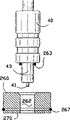
在本发明的此实施例中,喷射器40位于孔38中的位置相对于喷射器位于内燃机中的传统位置要更靠后一些。这样设置的理由将在以下说明书中变得明显。为将该喷射器40安装在更靠后的位置上,利用位于喷射器基底处的较大密封件44和46来取代环绕着喷射器的传统密封件,无论传统密封件还是较大密封件44和46均用于将喷射器密封在该孔38中,这样与传统相比,该喷射器40就可相对于气缸20更靠后一些。但是,如图2所清晰表示的,喷射器40的端部区域43位于孔38内,且自该端部区域43输出燃料,这样可自该喷射器40将燃料输送给气缸20。该端部区域43可具有一喷嘴41,自该喷嘴41输出燃料,或者可直接地自该端部区域43的端表面且经由该端表面内的多个孔(未表示)输送燃料。In this embodiment of the invention, the
此外,该喷射器40为一种传统喷射器,只是除去了通常环绕着其端部区域43的壳部件,以暴露该端部区域43。该端部区域43由传统喷射器的金属轴杆形成,这样可对该金属端部区域43进行加热,以加热该端部区域43内的燃料,以下将对其作更详细地说明。In addition, the
如图1所示,节流阀体48支承着一蝶形阀50,该蝶形阀50用于控制进入集管32内的空气流量。还安装有一空转螺旋线圈(idle solenoid)52,用于控制绕过该蝶形阀50的怠速空气(idle air)量。在传统的燃料输送系统中,空转螺旋线圈52包括一条空气通道53,该空气通道53是蝶形阀50的一条旁通气道,这样当关闭该蝶形阀50时(即,当发动机空转时),就绕过该蝶形阀50输送空气,以维持发动机内燃料的燃烧。As shown in FIG. 1 , throttle body 48 supports a
在本发明的第一实施例中,没有将空转螺旋线圈52直接安装在节流阀体48上。而是在该空转螺旋线圈52与节流阀体48之间提供一空闲块体55。In the first embodiment of the present invention, the freewheeling
如图4所清晰表示的,该块体55具有第一通道57,该第一通道57与节流阀体48的空气入口以及空转螺旋线圈52内的通道53连通。该块体55还具有第二通道57,该第二通道57也与通道53连通,且该第二通道57经由一连接件59与一怠速空气供应管60(参见图1)连通。As clearly shown in FIG. 4 , this block 55 has a first channel 57 communicating with the air inlet of the throttle body 48 and with the channel 53 in the free-running
封闭该节流阀体48内的怠速空气返回孔,因为本发明的此实施例不使用该孔,该怠速空气返回孔通常用于将空气自通道53传送至蝶形阀50的下游侧。The idle air return hole in the throttle body 48 that is normally used to route air from passage 53 to the downstream side of
回转至图1,排气集管12通常与发动机的排气系统71连接,以将该集管12中的废气排放到大气中。但是,在本发明的此实施例中,将具有热交换管62的一热交换器61插入该集管12与排气系统71之间。该管62具有凸缘63和65,该凸缘63和65分别与排气集管12上的凸缘以及排气系统71上的凸缘相啮合。Returning to FIG. 1 , the
怠速空气供应管60经由热交换管62侧壁上的一孔65a伸入该管62内,并与该管62内的热交换管66连接。如所清晰表示的,该热交换管66在管62内延伸,由此可在高温废气与怠速空气之间进行热交换,其中,高温废气经过该管62并流向排气系统71,而怠速空气流过怠速空气管60并流过该管62内的热交换管66。该热交换管66具有一进入孔67,这样,废气可流入该管66内,并与怠速空气相混合,如以下将要更详细描述的。一热空气返回管70与该管66的另一端连接,且经由管62壁内的一孔65b离开该管62。该热空气管70(如图2所清晰表示的)经由一分配管72上的凸起部69延伸至该分配管72。还提供一空气温度传感器73,以测量进入该分配管72的空气温度。The idle
该分配管72具有六条自该分配管72起向下伸展的降落管(droptube)74(全部六条都表示在图3中)。每条降落管74都与一孔75连通,该孔75钻在进气集管32中且与孔38连通,喷射器40位于该孔38内。如图2所清晰表示的,该管75近似与喷射器40的出气喷嘴41对齐。The
每个进气通道30内都具有用于输送燃料和空气的管78。在每个进气通道30内,该管78均自位于喷射器喷嘴41略微下游处的孔38起延伸至进气阀34的正上方。在每根管78内均设置有螺旋金属条形式的旋流器79,该旋流器79用于使流经管78的空气及燃料混合物成漩涡状,从而有助于空气、燃料以及废气的彻底混合、充分接触,如随后将要更详细描述的。Inside each
将该管78装入孔38内,且该管78的一端81通常向外扩张,从而便于使输送至孔38的燃料、空气以及废气的混合物进入该管78。The
在发动机的操作过程中,经由块体55内的通道57、通道53、接着再经由块体55内的第二条通道57将怠速空气抽入怠速空气供应管60内,在以上第二条通道57处将怠速空气输送给该管60。如同传统方式,当通过摇动发动机或者通过正常操作该发动机使活塞24在气缸20内往复运动时,就在发动机内的抽吸作用下经由空转螺旋线圈52抽入怠速空气。怠速空气流经管60并进入管66,在该管66处,怠速空气与自排气集管12排出且经由该管62流至排气系统71的废气之间进行热交换,从而加热该怠速空气。同时,一些废气还经由孔67进入该管66内,从而与该怠速空气混合,并经由热空气返回管70将上述混合气体输送至分配管72。该孔67的尺寸最好是这样设定的,使得废气成分占经由该管66所输送气体的10%至20%。因此,废气与流过怠速空气管60的怠速空气的比率为:10%至20%的废气,90%至80%的怠速空气。但是,所供应的怠速空气始终要足够用以在空转速度下操作该发动机。该孔67具有计量体积的作用,其利用废气流经管62的定向流动,使得进气体积由发动机速度及发动机载荷所决定,从而将经由该孔67吸入的废气量控制在以上所提及的优选比率范围内。将进入分配管72的废气与怠速空气的混合气体提供给每根降落管74,这样就将该怠速空气与废气的混合气体输送至孔38。经过管66的怠速空气与流经管62的废气之间进行热交换,从而加热该怠速空气;同时该经过管66的怠速空气还与经由孔67进入该管66内的废气相混合,从而进一步地加热该怠速空气。输送至分配管72的气体混合物的温度优选为大约80℃至120℃,更优选为大约100℃。During the operation of the engine, the idle air is sucked into the idle
经由降落管74及孔75将该高温气体输送至孔38,从而使该高温气体与喷射器40的端部43以及该喷射器40端部43上的喷嘴41紧密接触。这样就加热了该喷射器40的端部43和喷嘴41(如前所述,该端部43及喷嘴41由金属制成)。加热该喷射器40的端部43及喷嘴41就可提高该端部区域43内燃料的温度。加热该喷射器40的端部区域43内的燃料,同时在该喷射器内的压力作用下保持该燃料处于液体状态。但是,一旦在发动机控制单元的操纵之下,开启该喷射器以经由喷射器的喷嘴41喷射燃料时,随着燃料自该喷嘴41喷出,压力急剧降低,燃料将迅速地由液态转变为气态。该由液态至气态的转变是一个闪蒸效应(flashoff effect),由于燃料在端部区域43内被加热,而且自该喷嘴41喷出燃料的同时压力又迅速地下降,因而燃料迅速地气化。由此,在该喷嘴41喷出燃料的同时,燃料迅速地气化。当该燃料离开喷射器喷嘴41时,上述气化燃料与经由分配管72输送的高温空气与废气的混合气体相混合,以将该经由闪蒸效应生成的燃料蒸气维持在气态。随着燃料进一步地离开喷嘴41’气态燃料开始分散在该高温空气与废气的混合气体中。混合气体可能会略微地冷却,特别是在将该混合气体输送至气缸20之前,该混合气体就与自进气集管32进入的空气相混合的情况下(这种情况也发生在以下所述实施例中)。但是,由于已将该燃料维持在气态,且该燃料已完全分散在流向气缸的空气与废气的混合气流中,尽管燃料会略微冷却,但该混合气体仍然保持一个较高的温度,此温度比该蒸气未与高温空气和废气的混合气体相混合情况下的温度要高,因而该燃料不会冷凝并返回至液态。在任何情况下,为确保输送至气缸的燃料为气态燃料,必须确保自喷射器喷嘴41喷出燃料时该燃料迅速地转变为气态,同时在喷射之后维持该气态,直至该蒸气分散到流向气缸的气流中。一旦蒸气已经分散到该气流中,那么该蒸气冷凝的可能性就极小,因为该蒸气已经分散到气流中,且该蒸气与其它气体的混合物流至气缸20所需要花费的时间极短。因此,加热该端部区域43就可确保喷射燃料时,所喷出的燃料迅速地转变为气态,然后该气态燃料与高温空气和废气混合,从而维持该气态直至燃料蒸气分散到气流中。这一点与现有技术完全不同,在现有技术中喷射的是液态燃料,然后在所喷出燃料离开喷射器一段距离之后,再试图将该液态燃料转变为气态。The high temperature gas is conveyed to the
发动机由空转油门至全油门的不同油门位置将导致进气系统内的压力发生变化,从而改变所输入的高温气体的体积,因而受热气体与所输送的标准大气之间的比率也发生变化。由此,可相应地改变该空气燃料混合物的混合比。例如,与发动机的高载荷以及高速度相比,在较慢速度以及较小载荷系数的情况下,可使用较贫的燃料混合物。依据本发明的优选实施例,如同目前的理解,通常控制该燃料空气混合比,使Lambda远远高于1.00,该数值由针对普通发动机装置的工业最佳标准认定。在发动机速度较慢以及载荷系数较小的情况下,由于油门打得较小,自标准源吸入的空气较少,受热气体被稀释地程度较低,因此可将较高温度的混合气体输送给气缸。又由于标准源在较低的室温环境下工作,引入进气系统内的该吸入空气的起始温度较低,因此吸入空气的行进速率越快,混合气体的温度就越低。由于燃烧以及废气温度的负作用已被高温吸入空气的燃烧以及废气再循环所补偿,因而可以燃烧较贫的燃料混合物。将受热气体混合物引入燃烧室,其本身就可降低燃烧室的温度。这一点与废气中包含惰性气体相结合形成了这样一种系统,该系统可以控制通常贫油燃烧的发动机产生较高的燃烧室温度。由于吸入空气的密度低,因而吸入空气的温度仅能对相对的活塞产生较低的压缩阻力,从而有助于维持并改进该发动机在较少燃料下的较低速度转矩(speed torque)以及功率,所测量到的Lambda值可增大到1.25左右。Different throttle positions of the engine from idle throttle to full throttle will cause the pressure in the intake system to change, thereby changing the volume of hot gas input, and thus the ratio between heated gas and standard atmosphere delivered. Thus, the mixing ratio of the air-fuel mixture can be changed accordingly. For example, a leaner fuel mixture may be used at slower speeds and smaller load factors than at high engine loads and speeds. According to a preferred embodiment of the present invention, as currently understood, the fuel-air mixture ratio is generally controlled such that Lambda is well above 1.00, which is determined by industry best standards for common engine installations. At slower engine speeds and lower load factors, less air is drawn in from the standard source and the heated gas is less diluted due to lower throttle opening, thus delivering a higher temperature mixture to the cylinder. And because the standard source works at a lower room temperature, the initial temperature of the inhaled air introduced into the intake system is lower, so the faster the inhaled air travels, the lower the temperature of the mixed gas will be. Leaner fuel mixtures can be burned since the negative effects of combustion and exhaust gas temperature are compensated for by the combustion of high temperature intake air and exhaust gas recirculation. The introduction of the heated gas mixture into the combustion chamber itself lowers the temperature of the combustion chamber. This, combined with the inclusion of inert gases in the exhaust gases, creates a system that can control the higher combustion chamber temperatures produced by normally lean burn engines. Due to the low density of the intake air, the temperature of the intake air can only produce a low compression resistance to the opposing piston, thereby helping to maintain and improve the lower speed torque (speed torque) of the engine with less fuel and Power, the measured Lambda value can be increased to about 1.25.
随着载荷以及发动机速度的增大,油门打得更大,允许更多的空气进入该进气系统,受热气体与所吸入的标准室温空气之间的比率改变,因而输入气体的温度也发生变化。总输入气体的温度降低,因而增大了使输出功率最大化所需要的密度。这还增大了发动机自身的压缩阻力,增大了发动机操作过程中所吸收的能量,从而要求燃料空气混合比中燃料与空气更均衡,以补偿载荷、速度、阻力,但仍要求该发动机与以传统方式操作的发动机相比允许使用更贫的燃料混合物。较热的进气温度将降低燃烧室温度,这有助于抵消贫油燃烧的反作用。As load and engine speed increase, the throttle is opened more, allowing more air into the intake system, the ratio of heated air to standard room temperature air drawn in changes, and thus the temperature of the incoming air changes . The temperature of the total input gas is reduced, thereby increasing the density required to maximize output power. This also increases the compression resistance of the engine itself, which increases the energy absorbed by the engine during operation, thus requiring a more balanced fuel and air mixture ratio to compensate for load, speed, and resistance, but still requires the engine to be compatible with An engine operated in a conventional manner allows the use of a leaner fuel mixture than that. A warmer intake air temperature will lower the combustion chamber temperature, which helps counteract the adverse effects of lean burn.
废气循环的再一个作用是有助于降低燃烧室的温度,并允许燃烧更贫的燃料,而在传统发动机系统中减少燃料时,温度将急剧地升高。废气循环还有助于减少NOX,NOX是通常与燃烧贫油相关的另一项不利后果,在正常环境下,燃烧贫油的发动机将生成显著增多的一氧化氮。低空气密度可减小压缩阻力,这就允许在所输入燃料总量较少或在一次特定循环中所输入燃料较少的情况下,发动机可维持其功率及转矩。本发明优选实施例通过在喷射器的端部区域加热燃料,使得在燃料喷出后该燃料迅速地100%气化。这可长久维持部件的完整性,并使得在制造原始设备时能安装或组装得简便。高温燃料在喷射器内的压力下被高温释放,由于喷射器进行喷射时压力减小,而压力一减小液体就发生热膨胀,因此高温燃料能迅速地形成蒸气。此蒸气经过较短距离的进气区域,且当该蒸气在高温废气和/或高温燃烧空气中行进的同时,维持该蒸气处于气态,最终该蒸气又与其它标准输入空气流相混合,一旦该蒸气进一步地分散到该标准空气流中,就形成了一种组合供应气体,该组合供应气体的温度可根据载荷以及发动机的速度而发生变化。稀释该高温气体与燃料蒸气的混合物可防止在紧接着喷射操作且经由闪蒸效应形成蒸气之后的任何阶段中,该混合物再冷凝。如Lambda设置所论证的,减少发动机所使用的燃料既可通过减少用于形成蒸气的燃料来实现,又可通过减少在蒸气形成后用以获得适当燃料空气混合比所需要的液体燃料来实现,再加上由于在本发明优选实施例中引入了废气以及高温输入空气,因而允许发动机进行贫油燃烧。A further effect of exhaust gas recirculation is to help lower the temperature of the combustion chamber and allow leaner fuel to be burned, whereas in conventional engine systems temperatures would rise dramatically when fuel is reduced. Exhaust gas recirculation also helps reduce NO x , another adverse consequence often associated with lean burning engines, which under normal circumstances will generate significantly higher levels of nitric oxide. Low air density reduces compression resistance, which allows the engine to maintain its power and torque with less total fuel input or less fuel input in a given cycle. The preferred embodiment of the invention works by heating the fuel at the end region of the injector so that 100% of the fuel vaporizes immediately after it is injected. This maintains component integrity over time and allows for easy installation or assembly during original equipment manufacture. The high-temperature fuel is released at high temperature under the pressure in the injector. Since the pressure decreases when the injector injects, and the liquid thermally expands as soon as the pressure decreases, the high-temperature fuel can quickly form vapor. This vapor travels a short distance into the intake area and maintains the vapor in the gaseous state as it travels through the high temperature exhaust and/or high temperature combustion air, and eventually the vapor mixes with the rest of the standard input air stream, once the Further dispersion of the vapor into this standard air stream creates a combined supply gas whose temperature can vary depending on load and engine speed. Diluting the mixture of high temperature gas and fuel vapor prevents recondensation of the mixture at any stage immediately after the injection operation and the formation of vapor via the flashing effect. As demonstrated by the Lambda setting, reducing the fuel used by the engine can be achieved both by reducing the fuel used to form the vapor, and by reducing the amount of liquid fuel required after vapor formation to obtain the proper fuel-air mixture ratio, In addition, due to the introduction of exhaust gas and high temperature input air in the preferred embodiment of the present invention, it allows the engine to perform lean combustion.
用燃料蒸气来代替燃料蒸气和液体燃料的混合物还可提高该燃料点燃以及燃烧的功率及效率。液体燃料不能点燃,其被浪费并作为污染物排出,而没有对发动机效率起到任何积极的作用。Replacing a mixture of fuel vapor and liquid fuel with fuel vapor also increases the power and efficiency with which the fuel ignites and burns. Liquid fuel cannot be ignited, it is wasted and emitted as pollutants without any positive effect on engine efficiency.
气缸内用于点燃的蒸气量越多,所获得的压缩比就越大,该压缩比是通过缩小燃烧室容积或者换句话说通过将可燃混合物压缩至给定空间内而获得的。采用较大的力和功率来点燃该蒸气混合物,就不会发生提前点火或多次起爆以及火焰锋(flame front)等现象,在采用汽油的传统高压缩比发动机中,当该发动机爆燃或爆缸时都会出现这些现象。The greater the amount of vapor in the cylinder for ignition, the greater the compression ratio obtained by reducing the volume of the combustion chamber or in other words by compressing the combustible mixture into a given volume. Using greater force and power to ignite the vapor mixture, there will be no pre-ignition or multiple detonations and flame fronts. In a traditional high compression ratio engine using gasoline, when the engine deflagration or explosion These phenomena occur in all cylinders.
一旦在这种高压缩比下使用燃料,该燃料的燃烧率,确切地说,燃烧速度或者说在燃烧室内全部混合物完全燃烧所需要消耗的时间将减少,这意味着更多的可燃混合物将在压缩冲程的最有效阶段燃烧,该可燃混合物将燃烧得更充分,其中,在压缩冲程的最有效阶段,压缩幅度最大。这样在全部混合物燃烧后,排出气体成分也发生变化,在排出气体中,二氧化碳较多,而碳氢化合物和一氧化碳较少,排出气体成分是用于评估燃烧室内燃烧效率的一种常规方法。Once a fuel is used at this high compression ratio, the fuel's burn rate, or rather, the burn velocity or the time it takes for the entire mixture to burn completely in the combustion chamber, decreases, which means more of the combustible mixture will be in the combustion chamber. The combustible mixture will burn more fully as it burns during the most efficient phase of the compression stroke, in which the magnitude of compression is greatest. In this way, after the entire mixture is burned, the composition of the exhaust gas also changes. In the exhaust gas, there are more carbon dioxide and less hydrocarbons and carbon monoxide. The composition of the exhaust gas is a conventional method for evaluating the combustion efficiency in the combustion chamber.
燃烧速率加快意味着用以确保在每次循环过程中燃烧较大量蒸气所需要花费的时间变短。A faster burn rate means that it takes less time to ensure that a larger amount of vapor is burned during each cycle.
传统发动机为了在活塞开始其向下的行程或者说提升行程之前腾出足够的时间来燃烧尽可能多的燃料,依靠在活塞到达上死点(在每次特定循环过程中或者每次转动过程中,活塞位于发动机气缸的顶部时)之前就点燃该燃料空气混合物,其中,在提升行程之前,刚刚发生起爆。Conventional engines, in order to allow enough time for the piston to burn as much fuel as possible before it begins its downward stroke, or lift stroke, rely on the piston reaching top dead center (during each given cycle or revolution). , when the piston is at the top of the engine cylinder), the fuel-air mixture is ignited prior to where detonation occurs just before the lift stroke.
这种现有方式试图确保更充分的燃烧,这种方式在原理上是不具有生产价值的,因为在活塞仍然进行压缩时就启动点火过程,从而使活塞受到两个相对的力,首先是起爆力,该力推动向上移动或者进行压缩移动的活塞,直至该活塞经过上死点并开始其向下的提升冲程,从而使得起爆(detonation)不具有生产价值。This existing approach, which attempts to ensure a more complete combustion, is not productive in principle because the ignition process is initiated while the piston is still compressing, thus subjecting the piston to two opposing forces, the first being detonation Force that pushes the piston moving upwards or performing compression until it passes top dead center and begins its downward lift stroke, making detonation non-productive.
对于这种点火方式而言,实际上在混合物还没有到达最佳压缩时就点燃了该混合物。这意味着具有一延迟期(retarded timing),在燃烧室内的较佳压力以及较佳的燃烧器质量下,该延迟期可实现较低的燃烧室温度。这可进一步地控制燃烧温度,并相应地控制燃料空气比,以实现更贫的燃烧,而不会受到贫油燃烧温度的负作用。With this type of ignition, the mixture is actually ignited before it reaches optimum compression. This means having a retarded timing which allows for lower combustion chamber temperatures at better pressures in the combustion chamber and with better burner quality. This further controls the combustion temperature, and accordingly the fuel-to-air ratio, to achieve leaner combustion without being negatively impacted by the lean burn temperature.
将蒸气引入燃烧室对于发动机的总体性能而言具有另一方面的作用。在传统发动机中,当喷射大量的燃料以限制液气转换率时,由于时间限制,以及所输入的空气将在不能再将液体转换为蒸气或气体的那一点上得以饱合,这样多余的液体燃料就对燃烧混合物产生一负作用,熄灭由火花塞产生的火花,并完全阻止适当的或者任何类型的点燃,或者如果有任何引燃,由于大量的液体燃料会将火焰熄灭,因而燃烧将很微弱且不完全。The introduction of vapors into the combustion chamber has another effect on the overall performance of the engine. In a conventional engine, when large quantities of fuel are injected to limit the liquid-to-gas conversion rate, excess liquid will be saturated at the point where it can no longer convert liquid to vapor or gas due to time constraints and the incoming air will The fuel will then have a negative effect on the combustion mixture, extinguishing the spark produced by the spark plug and preventing proper or any kind of ignition at all, or if there is any ignition will be weak due to the large amount of liquid fuel which will extinguish the flame And not quite.
但是,若采用本发明的原理,将混合物引入燃烧室,随后压缩的已经是气体,那么就不会发生上述反作用。However, if the principle of the present invention is used, the mixture is introduced into the combustion chamber, and what is then compressed is already a gas, then the above-mentioned reaction does not occur.
自以上论述以及图2中可认识到,本发明没有加热该喷射器40的主体40a,从而确保不会损坏该主体40a内的操作部件,或者不会熔融该主体40a。此外,若要将端部区域43内的燃料加热至所需要的温度,并不需要自燃料管道42输送相当热的燃料给该喷射器40,若这样做会熔融该主体40a内的部件或者损坏该喷射器40。由此,可将主体40a维持在正常温度,而将端部区域43加热至所需要的温度以提高该端部区域43内燃料的温度,这样在自该喷射器40的喷嘴41喷出燃料之后,该燃料会迅速地闪蒸以及气化,其中,喷射器的操作部件设置在主体40a内,且将燃料引入该主体40a。As can be appreciated from the above discussion and FIG. 2, the present invention does not heat the body 40a of the
因此,在图1和2所示实施例中,自喷嘴41喷出燃料后,该燃料迅速地生成燃料蒸气,随后该燃料蒸气又与输入该孔38内的空气与废气相混合,并进入蒸气管78。当此混合气体经过该管78时,利用旋流器79使该空气、废气以及燃料形成漩涡状,以确保该燃料与高温空气和废气的混合物充分接触和混合。这样可在所喷出燃料由该管78的一端行进至靠近进气阀34的该管78的另一端的过程中,维持所喷出燃料处于气态(通常呈液滴状)。按照传统方式,经由进气集管32以及进气通道30提供额外的空气,以支持气缸20内燃料的燃烧。因此,在空转速度下,仅有空气燃料以及废气经由管78进入气缸20内。但是,一旦压下加速器并打开蝶形阀50,空气就可经由节流阀体48进入进气集管32以及进气通道30,从而供应给该气缸20。Therefore, in the embodiment shown in Figures 1 and 2, after the fuel is ejected from the
除了按以上所述方式(经由块体55)供应怠速空气外,也可自该蝶形阀50的下游获取怠速空气。在这种设置中,在该节流阀体48与进气集管32之间提供一块体(未表示)。该块体具有与蝶形阀下游相连通的孔,通常经由该孔输送怠速空气,该孔与管60连接。Instead of being supplied with idle air in the manner described above (via block 55 ), idle air can also be taken from downstream of the
由于燃料是经由管78输送给气缸的,而该管78与进气通道30相比,横截面积与容积均较小,因此在自管78的一端行进至该管78的另一端的过程中,可维持该燃料处于受热状态,并保持该燃料的温度。Since the fuel is delivered to the cylinder through the
在图2所示实施例中,该管78由孔38一直延伸到进气阀34。但是,在其它实施例中,该管78也可沿着进气通道30的长度仅延伸过一段路,通向该进气通道30,并与该阀34相隔一定距离。在又一种实施例中,可完全取消该管78。在高性能或高转速发动机中,例如赛车用发动机等,该管78最好具有图2所示的长度。在普通有轨电车的情况下,该管78最好更短一些,可自该孔38起仅延伸过进气通道30长度的十分之一。因此,在这种装置中,燃料蒸气、受热空气以及废气的混合物进入管78,沿着该管78行进较短的距离,然后流出该管78并进入进气通道30内,从而与经由进气集管32吸入该进气通道30内的吸入空气相混合。In the embodiment shown in FIG. 2 , the
优选的,管62内的热交换管66具有这样一种直径及长度,使得其热交换面积等于每升发动机容量大约50平方英寸,该管66的直径代表了在车辆怠速系统下的最小流通面积。管62的尺寸应该这样设定,使其能够维持排气集管12的正常废气流量特性。可用一种绝缘材料来覆盖该管62,以增强贮热能力以及与该管66的热交换。Preferably,
将废气与怠速空气相混合具有两个作用。第一,首先是加热流过管60的怠速空气,该怠速空气较冷且移动迅速,以使得由管62和管66组成的热交换器尽可能的小;第二,将废气混入空气流内,以降低排放物中一氧化氮的百分比含量。该管66最好具有波状或阶梯状轮廓,以使流经该管66的混合气体形成湍流,从而充分地混合该怠速空气和废气。与喷射器40的传统位置相比,将该喷射器40设置得距孔38的最内端更靠后大约1mm至4mm,但该距离应能使喷嘴41和端部区域43被来自降落管74和孔75的引入热气所包围。该管78的扩张端81不仅便于聚集气体和燃料的混合物,还可防止该管78落入发动机内,从而便于在进气通道30内定位该管78。最好将旋流器79紧配合(tight fit)在该管78内,从而利用摩擦将该旋流器79保持在其适当位置上,而不会落入发动机10内。如上所述,该蒸气管78的横截面积小于进气通道30以及进气阀34的横截面积,流过该管78的空气混合物的速度大于流过进气通道30的空气速度。这就使得更大量的受热气体经过燃料蒸气,与该燃料蒸气一起形成气体混合物自该管78引出,从而可增大给予该蒸气的总热传输量,确保该燃料处于气态。还提供了第二真空系统,并允许空载电路在将空气供应给发动机时转更大的圈(play a greaterroll),否则当油门打开时,其将超驰(overridden)。Mixing exhaust with idle air has two effects. First, the first is to heat the idle air flowing through the
这种作用改变了供应给传感器以及燃料控制系统的真空度,并将真空度维持在一个较高的水平,这反过来又防止喷出原始数量的燃料,并依据本实施例减少燃料数量。车辆的计算机在变化的信号下感知不同的操纵参数组,从而减少所需要的燃料数量。为进一步地改变传感器的感受力(perceptions),本实施例中的第二真空系统可供应另一种真空源,通过使每个所需传感器采用一条附加真空线来添加给原始设备。This action changes and maintains the vacuum level supplied to the sensor and fuel control system at a higher level which in turn prevents the original amount of fuel from being ejected and reduces the amount of fuel according to the present embodiment. The vehicle's computer senses a different set of handling parameters under varying signals, thereby reducing the amount of fuel required. To further vary sensor perceptions, the second vacuum system in this embodiment can supply another source of vacuum, added to the original equipment by having an additional vacuum line for each required sensor.
如前所述,加热该主体40a下方的端部区域43,电子部件容纳在该主体40a内,由于供应给喷射器的燃料是正常温度,因而容纳在该主体40a内的电子部件区域是冷的且在操作规程内。As before, the
由于喷射时燃料的温度较高,因而受热燃料可以极快的速度气化。与其它特征相结合,这一点意味着为了获得100%的气化,燃料或者加热气体在点火前都不需要位于燃料的终点温度附近。Due to the high temperature of the fuel during injection, the heated fuel can vaporize extremely quickly. Combined with other features, this means that in order to obtain 100% vaporization, neither the fuel nor the heating gas needs to be near the end temperature of the fuel before it is ignited.
对于吸入气体以及燃料而言,平均温度升高至80℃至120℃,加上该温度没有高至燃料的终点温度,再与速度、混合废气以及将燃料保持在蒸气管内的时间相结合,来准备将在燃烧室内点燃的该燃料蒸气以及废气/吸入气体混合物,可减少污染物、碳并提高效率。For the intake gas as well as the fuel, the average temperature increase to 80°C to 120°C, plus the fact that the temperature does not rise above the fuel's end temperature, is combined with the velocity, mixing exhaust, and the time the fuel is kept in the vapor tube to Preparing this fuel vapor and exhaust/inhalation gas mixture to be ignited within the combustion chamber reduces pollutants, carbon and increases efficiency.
采用最低温度以维持引入空气总量的容积效率。The lowest temperature is used to maintain the volumetric efficiency of the total amount of air introduced.
在相同性能下,将完全蒸气状态的燃料输送给气缸20,所需要的燃料减少,由此可改进经济效益。在传统发动机中,利用发动机10的发动机控制单元(未表示)来控制通过燃料喷射器40引入该发动机内的燃料数量。此单元可依据各种操作参数来控制该喷射器40,如以上所提到的,该操作参数包括输送空气的温度、发动机速度、真空率等。由于本实施例将燃料蒸气而不是燃料液滴输送给气缸20,因而所需要的燃料数量比该单元为特定操作条件所确定的数量要少。因此,如果本发明优选实施例采用这种传统单元,就应修改该单元,以使喷射器40喷射更少量的燃料,因为在本发明的这种实施例中,所需要的燃料量实际上比该单元为特定操作条件所确定的量要少。这可通过手动或自动地改变输入该单元内的某些参数来实现,以使该喷射器40喷射较少量的燃料。选择性的,如果所提供的系统为原始设备,那么也可修改该单元的操作软件,以使喷射器40输送本发明实施例所要求的较少量燃料,从而获得所需要的工作特性。Delivering the fuel in its complete vapor state to the
图5表示本发明的第二实施例,其中,与前述相同的参考数字表示相同的部件。Fig. 5 shows a second embodiment of the invention, in which the same reference numerals as before denote the same parts.
在本发明的这个实施例中,怠速空气供应管60与位于排气集管12上的热交换器90连接。该热交换器90可包括位于排气集管12上的一管,该管为S形构造,并利用来自排气集管12的热量加热该管。管60可贯穿该管,这样热交换就得以发生,从而加热经过该管60的怠速空气。In this embodiment of the invention, the idle
一隔块92与顶部16连接,且该隔块92具有孔94,该孔94对着排气通道14和排气集管12,以允许排出气缸20内的废气。该隔块92还具有钻入该隔块内且垂直延伸的孔96。为每个气缸20提供一个这样的孔96,且该孔96对着发动机10的排气通道14。一凹形(hollow)分配管98位于该隔块92的顶部上方,该管98的内部100与每个孔96连通。怠速空气供应管60包括自热交换器90延伸至该分配管98的一部分60a。喷射器40安装在该分配管98的顶部上且具有端部43和喷嘴41,该端部43和喷嘴41伸入分配管98的凹形内部中。来自管60a的热空气进入该分配管98,并围绕着且加热该喷射器40的端部43和喷嘴41,加热该端部43和喷嘴41就使得燃料在离开该喷嘴41的同时立即气化,与以上参照图1和2所述的方式完全相同。因此,在喷射的同时立即就生成燃料蒸气,并在该燃料蒸气和热气体沿着孔96行进的过程中,维持该燃料蒸气处于气态。A
在此实施例中,喷射器40位于发动机的排气侧,与图1和2所示实施例中将喷射器设置在进气侧相比,排气侧的环境温度比进气侧要高。利用经过管60a的热怠速空气来完成对该端部区域43的加热。在此实施例中,可使隔块92与管98绝热,或者利用一种非导热性材料来形成该隔块92,这样端部区域43就不会过热,否则将导致该端部区域43内的燃料气化,这将使得该喷射器无法正常工作。如前所述,加热端部区域43以将该端部区域43内的燃料温度提升到某个温度,在该温度下,燃料由于该端部区域43内的压力而仍然维持在液态,但一旦该燃料自端部区域43喷出,便会迅速地气化,从而确保该喷射器40能够正常工作,同时燃料在离开喷射器喷嘴41的同时迅速气化。In this embodiment, the
一根燃料空气输送管104与孔96连接,该输送管104经过排气通道14以及气缸顶部16内的孔道106。该管104一直穿过该孔道106,并进入发动机10的进气通道30中。将该管104封入该孔道106内,这样废气就不能围绕着该管104、经过孔道106而进入该进气通道30。Connected to bore 96 is a fuel
自该喷射器40喷出时生成的燃料蒸气与来自管60a的热空气相混合,并经由每个孔96将该混合气体输送至对应的每根管104。该燃料空气混合物经过位于排气通道14内的管104的一部分,这样,可通过与该排气通道14排出的高温废气进行热交换来加热该燃料空气混合物。这有助于在该燃料沿着管104流至出口端109的过程中,维持该燃料的气态,其中,该出口端109位于进气通道30内。Fuel vapor generated when ejected from the
该管104具有一进气孔108,该进气孔108位于管104的一个部分上,该部分位于自排气通道14流向排气集管12的废气流中。如图5所示,该孔108位于隔块92内的孔94中。但是,该孔也可位于管104的其它部分,只要废气能够进入该孔108,从而与燃料和空气相混合,以进一步地加热该管104内的燃料空气混合物。因此,也可如早期的实施例,在燃料沿着该管104流至出口端109的同时使该燃料气化,并将蒸气状态的燃料输送给进气通道30。The
如前述实施例,经过管104的空气和废气的温度在80℃至120℃的范围内,发动机在空转速度下最高温度可达到150℃。此实施例具有同前述实施例大体相同的优点,少量的热怠速空气以及废气与燃料相混合,以确保经由进气通道30将该燃料输送给气缸20时,该燃料处于完全气化状态。当蝶形阀50(图5中未表示)打开时,可经由该进气通道30提供用于支持气缸20内燃料燃烧所需的额外空气。As in the previous embodiment, the temperature of the air and exhaust gas passing through the
图6表示了本发明的另一种实施例,其与图5所示实施例大体相同,只是该管60直接连接到分配管98上,而没有经过任何初级热交换器,例如参照图5所述的热交换器90。但是,此实施例与图5所示实施例的另一个重要区别在于,分配管98与隔块92之间存在热传递,该隔块92进一步地又与发动机的排气集管和排气通道之间存在热传递。因此,可经由该隔块92将热量传递给分配管98,由于喷射器40的端部区域43与该分配管98之间相互接触,因而可以加热该端部区域43。由于喷射器40、管98以及隔块92均位于发动机的排气侧,该排气侧是发动机中温度最高的部分,因而尽管该端部区域43与分配管98之间的接触面积相对较小,但对该端部区域43的热传递仍然是十分显著。直接来自空转螺旋线圈的空气60不仅提供了用于燃烧的怠速空气,还略微地降低了端部区域43的温度,以确保该端部区域43不会过热。当该怠速空气进入分配管98且与端部区域43紧密接触时,利用该分配管98与端部区域43之间的热传递来加热该怠速空气,从而将该端部区域43维持在所需要的温度上,以将该端部区域43内的燃料维持在这样一个温度,在该温度下,燃料仍处于液态,但可确保自喷嘴41喷出燃料的同时该燃料迅速地成为气态。另外,图6所示实施例的操作方式与图5所示实施例完全相同。Fig. 6 has shown another kind of embodiment of the present invention, and it is substantially identical with the embodiment shown in Fig. 5, just this
如图5和6所示,最好将管104的端部109切削成一定角度,以增大该管104内的真空量,该真空量是开启进气阀34且经由进气通道30将空气抽入气缸20内时通过抽吸产生的。As shown in FIGS. 5 and 6, it is preferable to cut the
图7表示了本发明又一种实施例,再一次地采用与前述相同的参考数字以表示相同的部件。Figure 7 shows yet another embodiment of the present invention, again using the same reference numerals as previously described to denote the same parts.
在本发明的这种实施例中,与本发明第一实施例的图2所示位置相比,喷射器40位于孔38内的传统位置上。In this embodiment of the invention,
在本发明的这种实施例中,喷射器40的端部区域43位于一个环状件260内,以下将参照图17至22更详细地说明该环状件260。该环状件260具有一中央孔262,端部区域43紧贴地位于该中央孔262内,以接触该中央孔262的周边壁。该环状件260与进气集管32接触并与之进行热传递,这样,顶部16以及气缸壁22内产生的热量就经由该进气集管32传递给环状件260,然后再传递给喷射器40的端部区域43以加热该端部区域43。这就提升了该端部区域43的温度,从而加热燃料。因此,当自喷嘴41喷出燃料时,就发生如前所述的闪蒸效应,使得燃料迅速地气化。In this embodiment of the invention, the
依照本发明的这种实施例,顶部16内形成有一条孔道106,该孔道106连接排气通道14和进气通道30。一根空气燃料输送管120位于进气通道30内。该管120具有废气进入支管122和空气进入支管124,该废气进入支管122伸入孔道106内且被封入该孔道106中,该空气进入支管124伸入进气集管32并向该进气集管32敞开。在这种实施例中,按照通常的传统方式经由空转螺旋线圈输送怠速空气,以及经由进气集管32和进气通道30输送额外空气。According to this embodiment of the present invention, a
空气和燃料的输送通道具有对着喷射器喷嘴41的进气端128,这样自该喷射器40喷出的燃料就经过该进气端128,并沿着管120流至位于阀34附近的出气端130。The air and fuel delivery passage has an inlet end 128 facing the
废气可自排气通道14经由孔道106流入支管122内。一根波状的热交换管132自该支管122起伸入支管124内,且终止于该支管124的开口端136附近。将该管132封在支管122内,这样废气就不能绕过该管132而直接进入管120内。流过该管132的废气加热该管132,从而与自喷射器40流经该管120的燃料以及自支管124流至端部130的空气进行热交换,以保持该燃料处于气态,与参考先前实施例所述的方式相同。The exhaust gas can flow into the
吸入的空气可经过支管124的开口端136,然后进入管120内,这样该空气就与喷射器40输送的燃料相混合。通过与该管132进行热交换来加热该空气和燃料的混合物。来自孔道106且流经管132的废气自该管132的出口端140排出(清晰地表示在图8中)。该出口端140的附近具有通常为圆盖形的折流板144,该折流板144使得自该管132端部140排出的废气如箭头A所示方向、沿着支管124并远离开口端136偏回。同时,还经由该开口端136吸入进气集管32内的空气,这样该空气就与废气以及由喷射器40输送的燃料相混合,同样也有助于在燃料自管120的端部128流至该管120的端部130的同时,维持该燃料处于气态。因此,如前述实施例,可将蒸气状态的燃料输送给气缸20。Inhaled air may pass through the
如前述实施例,在此实施例中,最好除去用于包裹该喷射器40的端部43的壳部件,以通过该端部43与环状件260之间的热传递以及该环状件260与进气集管32之间的热传递来加热该端部43。As in the preceding embodiments, in this embodiment it is preferred to remove the shell member that encloses the
在图1至8所示实施例中,所示的燃料空气输送管78、104和120均为安装在发动机的进气通道内的一根单独管。但是,除了提供单独管之外,上述管也可形成在气缸顶部的铸件内,或者说仅在该气缸顶部的铸件内钻孔而得以形成,这样它们就与原始制造的气缸顶部形成一体,并作为该气缸顶部的一部分。如果需要的话,其它各管也可与发动机一体形成,而不是提供单独的管。由于这些管仅占据相当小的空间,并与发动机的现有部件相连接,因而能简便地通过安装前述实施例中所公开的各管,而将本系统应用于原始制造设备(即,制造好的发动机),正如将传统输送系统安装在现有发动机上一样。In the embodiment shown in Figures 1 to 8, the fuel
图9和图10表示了本发明的又一种实施例。在这种实施例中,用以界定气缸20的块体壁150内具有多个洞152。套筒154插入该每个洞152内。每个洞152内都具有一直径减小的孔154,该孔154使洞152与块体壁150相互连通,套筒154具有伸入该孔154内的杆座(stem)156。喷射器40位于该套筒154内,且其喷嘴41伸入该杆座156中,这样就可将燃料直接喷入气缸20内。9 and 10 show yet another embodiment of the present invention. In such an embodiment, a plurality of
提供进气阀34和排气阀18,分别用于控制将空气引入该气缸20内以及用于控制自该气缸20内排出废气。活塞24按照传统方式在该气缸20中往复运动。An
如在先前实施例中所述的相同方式,除去包裹着该喷射器40的端部区域43的壳部件,以使该端部区域43经由套筒154与气缸壁150接触。这样,就可在该壁150与端部区域43之间进行热交换,以加热该端部区域43内的燃料,实现先前实施例中所述的相同效果。也就是说,一旦自该喷射器40中喷出燃料,该燃料就迅速地闪蒸为气态。In the same way as described in the previous embodiment, the shell part surrounding the
在本发明的这种实施例中,推迟自该喷射器40中喷出燃料的时间,以当活塞24在气缸20内上升时,能将喷射器40内的燃料直接喷射到该活塞24的顶部上,这样在利用火花塞(未表示)或者在柴油机的情况下利用压缩来点燃该燃料蒸气之前,沉积在该活塞24上的燃料将有助于使任何未气化的燃料气化。In this embodiment of the invention, the timing of fuel injection from the
因此,如果该喷射器喷出任何液态的燃料,事实上如上所述,喷射到该活塞24顶部上的燃料将在点燃该燃料之前气化。Therefore, if the injector sprays any liquid fuel, as described above in fact, the fuel injected onto the top of the
在本发明的优选实施例中,该套筒154内的洞152向外略微呈锥形,这样其外端170就稍微大于内端172。这就能将不同尺寸的喷射器40插入该套筒154内,并确保喷嘴41位于杆座154内,从而可将燃料直接送入气缸20中,同时还可加热该喷射器的端部区域以及该端部区域内的燃料。In a preferred embodiment of the invention, the
燃料管180用于将燃料输送给该喷射器40,该燃料管180经过具有入口192和出口194的热交换器190。废气自该入口192进入并自该出口194排出,用于加热该热交换器190内的燃料管180。选择性的,来自冷却系统的热水或者发动机的油类可自该入口192进入并自该出口194排出,以与流经该燃料管180的燃料进行热交换。在另一种实施例中,可在该热交换器190内利用电加热该燃料管180。A
对流经该燃料管180的燃料进行加热就完成了对燃料的预热,这样当将该燃料输送给喷射器40时,该燃料是温热的,从而当将燃料沉积到发动机内的热活塞24上时,该燃料更易于气化。如果壁150不能将足够的热量传递给端部区域43,以将该端部区域43的温度提升到当自喷射器40喷出燃料时该燃料能够闪蒸或迅速气化所需的温度,那么利用热交换器190来预热燃料就相当有用。理由在于,该壁150可能由于在发动机中循环流动的冷却液而使得其温度过低,无法将端部区域43内燃料的温度提升至可产生闪蒸效应的温度。在热交换器190内预热燃料可在该燃料进入喷射器40之前略微地提高该燃料的温度,这样由该壁150所传递的热量就足以产生闪蒸效应,而不会使流经喷射器40的燃料过热,这将损坏该喷射器40。Preheating the fuel is accomplished by heating the fuel flowing through the
最好除去喷射器40的所有密封部件和壳部件,并将该喷射器40封入套筒154内以代替该壳部件。应认识到的是,当活塞在压缩冲程中上升并经过孔152之后,将不再有压力作用给该喷射器40,其中,该压缩冲程用来压缩气缸20内的燃料和气体。如图9所示,该孔152和杆座156向下倾斜,以防止燃油聚集在该杆座156内。It is preferred to remove all sealing and housing components of the
如前所述,操纵喷射器40以将燃料输送至活塞24的顶部,当燃料喷射到该活塞的顶部时,利用该活塞24顶面具有较高的工作温度,将该活塞顶面作为一种蒸发器来气化该燃料。优选的,热交换器190加热该燃料,以在将该燃料输送至喷射器40之前,该燃料的温度达到大约50℃至80℃。As previously described, the
图11表示了本发明的另一种实施例,其中,与前述相同的参考数字表示相同的部件。Fig. 11 shows another embodiment of the present invention, in which the same reference numerals as before denote the same parts.
如同图1和2所示的实施例,空转螺旋线圈52向怠速空气管60供应怠速空气。但是,在这个实施例中,该空转管60具有一T形件200,这样既可将空气引入支管60′内,又可将空气引入支管60″内。该支管60′与热交换器61连接,图11a表示了该热交换器61的一种改良形式。如同前述实施例,热空气管70接收来自该热交换器61的热怠速空气以及一些废气,并将该混合气体输送给T形件201。该T形件201与分配管72连接,还接收来自支管60″的怠速空气。给该支管60″提供一电磁阀202,基于温度传感器203在分配管72内所检测到的温度来开启以及关闭该电磁阀202。该传感器203可仅当其所检测到的温度超过某一预定值时将信号经由导线204输送给电磁阀202,或者该传感器203可与管理系统或计算机连接,该管理系统或计算机反过来向电磁阀202提供信号以驱动该电磁阀。当该电磁阀202启动时,怠速空气可以经由支管60″流至T形件201,然后进入分配管72。当该电磁阀202关闭时,怠速空气就不能经由支管60″流至T形件201以及分配管72。该分配管72与先前所述的孔38连通,这样,来自热空气管70的高温废气和空气的混合物将流经喷射器40的端部区域43,从而在该喷射器40的喷嘴41喷出燃料之前,加热该端部区域43内的燃料。因此,如前所述,当燃料离开喷嘴41时,该燃料迅速地成为蒸气,这样,该燃料就在高温空气和废气的气流中自孔38输送至气缸20,并与吸入进气集管32内的吸入空气相混合。As with the embodiment shown in FIGS. 1 and 2 , idler
在发动机的正常操作过程中,自热空气管70进入分配管72内的该废气和空气混合物的温度可能远远高于所需要的用以将端部区域43加热至规定温度的温度。根据当天的热度以及发动机的工作条件,该高温空气和废气混合物的温度可能高达220-240℃。在该高温气体进入分配管72之后,该气体的温度可以降低至160-175℃,但此温度仍然高于所需要的用于将端部区域43加热至规定温度以使燃料闪蒸的温度。此较高温度将使该端部区域43内的燃料气化,从而导致喷射器40发生故障或者操作错误。如果传感器403检测到分配管72内的温度高于某个预定值,例如150℃,就开启电磁阀202,使低温怠速空气经由支管60″进入该分配管72,从而将该分配管72内空气混合物的温度下降至150°C。此温度足以将端部区域43内燃料的温度提升至这样一种温度,在该温度下,燃料仍然处于液态,但一旦自喷射器40喷出该燃料,该燃料将闪蒸为气态。如果温度下降至150℃以下,就关闭该电磁阀202,以阻止低温空气继续经由支管60″进入分配管72,因而通过选择性地开启和关闭该电磁阀202,可将该分配管72内的温度维持在大约150℃。During normal operation of the engine, the temperature of the exhaust gas and air mixture entering the
开启电磁阀202以打开支管60″的操作具有双重作用,一个作用是减少流入支管60′的空气量,从而减少热空气管70所接收到的热空气,另一个作用是经由支管60″将低温空气直接供应给分配管72,从而起到冷却作用。The operation of opening the
在这个实施例中,还提供与车辆废气系统相连通的第二废气管70′。该管70′可简单地与废气系统的合适部分连接,从而使废气能够进入该管70′。利用第二电磁阀202′来控制该管70′,经由导线204′提供的信号来驱动该电磁阀202′。当为加快速度或增加载荷而踩下油门踏板,从而导致发动机真空系统中的压力下降时,就启动了该电磁阀202′。打开该第二阀202,废气就能自管70′进入T形件201内,从而可将该废气与管70内的空气一起提供给孔38。在高载荷或高速度的要求下,引入额外的废气将进一步地有助于减少所排出废气中的NOx气体。In this embodiment, a second exhaust pipe 70' communicating with the exhaust system of the vehicle is also provided. This tube 70' can simply be connected to a suitable part of the exhaust system so that the exhaust gas can enter the tube 70'. The tube 70' is controlled by a second solenoid valve 202', which is driven by a signal provided via wire 204'. The solenoid valve 202' is activated when the accelerator pedal is depressed to increase speed or load, causing a pressure drop in the engine vacuum system. Opening this
可利用一压力开关来操纵电磁阀202′,当压力下降时,该压力开关就经由导线204′将电流输出给该电磁阀202′,以启动该电磁阀202′。选择性的,也可利用发动机控制单元来启动该阀202′。在空载或低载过程中,通常使该第二阀202′处于关闭状态,因为在这些操作条件下不需要额外的废气。A pressure switch can be used to operate the solenoid valve 202', and when the pressure drops, the pressure switch outputs current to the solenoid valve 202' via the wire 204' to activate the solenoid valve 202'. Alternatively, the valve 202' can also be activated by an engine control unit. During no-load or low-load, the second valve 202' is normally left in a closed state, since no additional exhaust gas is required under these operating conditions.
图11a,11b和11c表示参照图1所述的热交换器61的一种变化形式。在这种实施例中,热交换器61比较短且包括一管205,管66卷绕在该管205内,且该管66与管60′的端部65a连接。如同前述实施例,该管66自热交换器引出,且其端部65b与管70连接。如前所述,该热交换器61具有法兰204,可将该法兰204栓接到发动机的排气管上。端部205将被焊接到发动机的排气集管12(未表示)上。这种设置所提供的热交换器比前述实施例要短,但是该热交换器却执行同参照图1和2所述实施例相同的功能。如参照图1和2所述,管66包括一孔67,废气可经由该孔67进入该管66内,这样就将空气与废气的混合气体提供给热空气管70,并输送给分配管72。Figures 11a, 11b and 11c show a variant of the
图12表示图11所示实施例的一种变形。在图12中,怠速空气管60与T形件201连接,以供应怠速空气。如参照图11所述的方式,电磁阀202根据温度传感器203所检测到的温度,控制怠速空气经由该管60的流动。该T形件201接收来自热空气管70的废气,来自该热空气管70的气体中不包括任何怠速空气,并将该废气输送给分配管72以及喷射器40的端部43,从而为了如前所述的目的对该端部43进行加热。图12A表示该管70与一锥形体210相连通,该锥形体210位于法兰211和法兰212之间。利用螺栓213连接该法兰211和212,以将该锥形体夹在并封在法兰211和212之间,从而使排气集管12与废气管61连通。FIG. 12 shows a modification of the embodiment shown in FIG. 11 . In FIG. 12, an
如图12A,12B和12C所清晰表示的,锥形体210接收该管70,该管70伸入锥形体210的周边壁215内,然后向下伸过该锥形体210的底部开口216,以伸入排气管61内。由此,当向该管70施加抽吸力时,就将高温废气抽入该管70内,并输送给T形件201。因此,在本发明的这种实施例中,沿热空气管70仅输送废气,以为了如前所述的目的对端部区域43进行加热。当分配管72内的温度升高至高于以上所提到的温度时,就启动电磁阀202,这样怠速空气就可经由怠速空气管60进入该分配管72内,从而冷却流向该端部区域的气体,如参照图11所述的。As shown clearly in Fig. 12A, 12B and 12C,
图12所示实施例还包括另外一个电磁阀202′和另外一条管70′,两者的功能同参照图11所述相应部件的功能相同。在这种实施例中,该管70′仅供应废气,该管70′可在管70与排气系统相连接的位置附近与该管70连接,如参照图12B至12D所更详细描述的,从而在改变速度或改变载荷的过程中提供额外的废气流。The embodiment shown in FIG. 12 also includes another solenoid valve 202' and another tube 70', both of which have the same functions as the corresponding components described with reference to FIG. In such an embodiment, the pipe 70' supplies exhaust gas only, and the pipe 70' may be connected to the
应认识到是,在这个实施例中,由于怠速空气没有与经由热空气管70供应的废气相混合,因而给进气集管提供了一条传统的怠速空气通道,该通道用于当关闭电磁阀202以阻止空气流过怠速空气管60时供应怠速空气。It will be appreciated that in this embodiment, since the idle air is not mixed with the exhaust gas supplied via the
图13所示实施例的操作原理同图11所示实施例相同,只是用一分配块体部件220来代替分配管72。相同的参考数字表示同图11所述相同的部件,这种实施例的操作方式同参照图11所述的方式相同。The principle of operation of the embodiment shown in FIG. 13 is the same as that of the embodiment shown in FIG. The same reference numerals designate the same parts as described with reference to FIG. 11, and this embodiment operates in the same manner as described with reference to FIG.
在这种实施例中,热空气管70和支管60″插入一块体221内,该块体221具有用于分别接收该管70和支管60″的一对孔222,且该两孔222在端部223处相互连通。块体221具有外螺纹224。一块体225内具有空腔226,该空腔226具有与该螺纹224相啮合的内螺纹228a,从而使块体221和225啮接到一起。该内部空腔226与多条独立的通道227连通,该各条通道227分别对应于采用本系统的发动机内的每个气缸。每条通道227都具有一根热空气及燃料输送管228,该输送管228延伸至连接管229。应注意的是,图13中仅表示了一根管228和一根连接管229(以及一个燃料喷射器40)。该连接管229为一根长度较短的管,且其下端部229a的直径较小。由此,就可按照同上所述相同的方式,将高温废气以及空气的混合物输送给安装在孔38内的喷射器40的端部43。In this embodiment, the
在这个实施例中,该块体225的周边壁内提供有温度传感器203,用于检测空腔226内热空气和废气混合物的温度。In this embodiment, a
图14表示采用图13所示分配器机构的一种实施例,但却应用于图12所示仅将废气输送给管70的实施例。因而,这种实施例的工作方式与参照图12所述的方式相同,分配器部件220的构造与参照图13所示构造相同。FIG. 14 shows an embodiment using the distributor mechanism shown in FIG. 13, but applied to the embodiment shown in FIG. Thus, this embodiment operates in the same manner as described with reference to FIG. 12 and the construction of the
图13和14所示实施例中还包括另一电磁阀202′,该电磁阀202′的操作方式分别同参照图11和12所述的方式相同。The embodiment shown in Figures 13 and 14 also includes a further solenoid valve 202' which operates in the same manner as described with reference to Figures 11 and 12, respectively.
图15更详细地表示了喷射器40与管229之间的组装。Figure 15 shows the assembly between
在此图中可清晰地看到,管229中直径缩小的端部229a将热空气和废气的混合物引向端部43,从而为了如上所述目的加热该端部43内的燃料。自喷嘴41经过孔38的燃料蒸气进入发动机的进气通道30内,而没有提供用于将该热空气废气混合物和燃料蒸气输送给发动机气缸的额外管路或通道。如图15中明显所示,在管229的直径缩小端229a内具有一孔233,喷射器40的端部43插入该孔233内。利用O形密封环234将该端部43封在该孔233内。该直径缩小端229a具有与孔233相对的开口235,利用O形密封环236将该开口235封在孔38内。由此,管229a的端部就形成了围绕该喷射器40端部43的一密封区域,这样,热空气和废气的混合物就可与该端部43紧密接触并包围该端部43,以按照如前所述的方式加热该端部43。喷嘴41经由开口235暴露于孔38,从而将燃料蒸气以及来自管229的热空气废气混合物输送至孔38以及发动机的气缸。As can be clearly seen in this figure, the reduced
图16表示图15所示实施例的一种变形,其中,在管229的直径缩小端229a内具有一体形成的一根蒸气管78,该蒸气管78实际上是与开口235连接。该管78的功能同参照图1所述的管78的功能相同,该管78可如图2所示一直延伸至进气阀34,或者沿着发动机的进气通道30仅延伸一段路。如前述实施例,该管78内可具有一旋流器79。FIG. 16 shows a variation of the embodiment shown in FIG. 15 in which a
图17至23表示本发明的又一种实施例。17 to 23 show yet another embodiment of the present invention.
图17表示一种热传递环260,该环260具有一中央孔262,该中央孔262用于接收喷射器40的端部区域43。如图18所示,端部区域43位于孔262内,且利用O形密封环263来密封该端部区域43。该环260内具有用于容纳O形密封环267的槽266,该O形密封环267将密封该环260,如以下参照图21所述。该环260具有用于接收管269的孔268,该管269经由形成在环260的底表面270内的开口269向外输出来自该管70的废气或热空气。该开口269可如图17a所示为新月形,或者如图18a所示为圆形。在这个实施例中,通过使该环260与发动机的某个高温部分例如进气集管相接触来加热该环260,另外根据该环260的特性及其制造材料,还可利用来自热空气管70的热废气或热空气提供额外的热量。同样,加热该环260,以将端部区域43的温度提升到所需的用于加热该端部区域43内燃料的温度,这样如前所述,当喷射燃料时,该燃料可以迅速地闪蒸为蒸气。FIG. 17 shows a
按照先前实施例中所述的相同方式,将废气提供给该热空气管70。如果需要使用热空气,可收集来自发动机高温区域例如发动机散热器附近的热空气,以将该热空气供应给环260,从而便于加热该环260。Exhaust air is supplied to the
如图21所示,该环260位于孔38中的进气通道30内,因而该环260可将热量传递给进气集管,铝环260的预期温度应维持在80℃与150℃之间。As shown in Figure 21, the
图19和20所示装置与图17和18所示装置相似,但在此装置中,单纯依靠发动机传递的热量和该环260与发动机之间的接触来加热端部区域43,并维持自喷嘴41所喷出的燃料处于气态。在这个实施例中,该环260由例如不锈钢制成,不锈钢材料易于被加热且能将其热量保存相当长的时间,因而不再需要经由热空气管70提供额外的热量。由此,在这个实施例中,通过发动机受热部分与该环260之间直接的热传递以及随后该环260与喷射器40端部区域43之间直接的热传递来提供所需要的用于提高端部区域43温度的热量。通过自散热器获取空气,可增加普通燃烧空气的温度以将燃料维持在气态。当燃料蒸气离开喷射器40时,进入进气集管内的该普通燃烧空气的热量可为该燃料蒸气提供一个温热的环境,以在该燃料蒸气自喷射器40起行进直至分散到空气流内之间的短距离内维持该蒸气处于气态。因而,这可防止该蒸气冷凝,并返回至液态。The arrangement shown in Figures 19 and 20 is similar to the arrangement shown in Figures 17 and 18, but in this arrangement, heat transfer from the engine and contact between the
图22表示设置在放大孔38内的图19和20所示环260,其设置方式同图21所示方式相同。FIG. 22 shows the
自图21和22可清晰地看到,利用O形密封环267将该环260密封在放大孔38内。As best seen in FIGS. 21 and 22 , the
在图22所示实施例中,由于没有向该环260提供额外的热空气和废气,若采用上述操作将有助于加热该环260,进一步地又有助于加热该喷射器40的端部43,同时也没有热空气废气混合物直接进入该孔38内以与自喷嘴41喷出的燃料蒸气相混合,因而理想的是,在将燃料提供给该喷射器40之前预热该燃料。为预热燃料,可使该燃料在输送至喷射器40之前经过图23所示热交换器280,该热交换器280包括卷绕在容器283中的燃料管282,热液体自入口284进入该容器283并自出口285离开该容器283。该液体可为来自发动机冷却系统的热水、燃油或其它任何适当的液体,该液体与燃料管282进行热交换,并在将燃料输送至喷射器40之前预热该燃料。应认识到的是,预热程度不足以将燃料加热至先前所述的气化点,仅仅是提供额外的预热以便于在端部区域43内将该燃料温度提升至所需温度,这样当喷嘴41喷出燃料时,该燃料能如前所述方式迅速地气化。In the embodiment shown in FIG. 22, since no additional hot air and exhaust gas are provided to the
图24和25表示本发明的另外两种实施例。在先前所述实施例中,经由通向气缸的通道(即,经由进气通道)输送燃料蒸气以及用于加热喷射器端部的某些废气,从而将该燃料蒸气和燃烧空气抽入气缸内。给该气缸提供某些废气的优点是,有助于在燃料自喷射器行进至气缸的途中,将该离开喷射器的燃料维持在气态,但是,提供废气也具有一个缺点。该缺点是提供废气就稀释了经由进气集管32供应的吸入空气,从而与未安装废气流通系统的发动机相比,发动机进气冲程的给定空气量减少,结果,由于与燃料相混合的每单位体积空气即空气密度减小,从而使得功率降低。尽管废气对于NOX的排放起到正面作用,但车辆废气的总排放量却增加。在将抽入发动机内的燃烧空气供应给气缸之前,利用废气预热该燃烧空气也导致NOX排放量的增大。此外,一氧化碳的排放量也增大。Figures 24 and 25 show two other embodiments of the invention. In the previously described embodiments, the fuel vapor and combustion air are drawn into the cylinder by delivering the fuel vapor through a passage to the cylinder (i.e., via the intake passage) along with some of the exhaust gas used to heat the injector tip . Providing some exhaust gas to the cylinder has the advantage of helping to maintain the fuel leaving the injector in a gaseous state as it travels from the injector to the cylinder, however, providing exhaust gas also has a disadvantage. The disadvantage is that the supply of exhaust gas dilutes the intake air supplied via the
图24和25所示实施例具有先前所述实施例的优点,同时还避免了以上所述缺点。The embodiment shown in Figures 24 and 25 has the advantages of the previously described embodiments while avoiding the disadvantages described above.
首先参照图24,相同的参考数字表示同前述相同的部件,发动机出气通道14的出口上提供了一个法兰400,排气管(未表示)或排气集管(未表示)与该法兰400连接以将废气排放到大气中。如同惯例,该法兰400为环形且具有一外围环形壁400a,该环形壁400a限定了一个中央开口400b,废气经由该中央开口400b流向车辆的排气系统。一根废气供应管402与法兰400连接,穿过壁400a且伸入该法兰400的开口400b以及排气通道14的路径中。该管402具有对着通道14的斜切端部403,这样自该通道14排出的废气易于流入该管402内。一根废气返回管405也与法兰400连接,其按照同管402相同的方式伸入该法兰400内并位于该管402的旁边。该管405具有背对着通道14的斜切端部406,这样当废气排出通道14并经过法兰400时,就在该端部406处产生文丘里效应,从而易于自该管405排出废气。可将该管402和405焊接或固定到法兰400上,以与该法兰400永久连接。Referring first to Figure 24, the same reference numerals represent the same components as previously described, a flange 400 is provided on the outlet of the
该管402和405与喷射器的外壳408连接,该外壳408通常为空心圆柱体且具有通向出气孔410的渐缩端壁409。管402与该圆筒形外壳408周壁内的一孔411连通,该孔411示意性地表示在图24中。管405也与该外壳408周壁内的一孔(未表示)连通,该孔通常与孔411径向相对。喷射器40与先前所述的喷射器相同,但其端部43容纳在该圆筒形外壳408内。在靠近渐缩壁409的该圆筒形外壳408的内周缘上,第一密封件412密封该端部43;在远离出气孔410的该圆筒形外壳408的内周缘上,第二密封件413密封该端部区域43。由此,该密封件412和413限定了一个环绕着端部43延伸的室415,该室415经由孔411以及与管405连通的对应孔与该管402和405连通。The
如图24所示,将该圆筒形外壳408压配合在传统发动机中用于容纳燃料喷射器的孔38中,并利用喷射器40以及该喷射器40与燃料管道42之间的连接将该圆筒形外壳408保持在其适当位置上。由此,就可防止该圆筒形外壳408移出该孔38。如图24所示,在该外壳408中,与管402连接的孔411以及与管405连接的对应孔位于朝向燃料管道42且伸出该孔38的外壳408部分上,因而不会妨碍将该外壳408插入孔38内的插入操作。通过焊接使该管402和405永久地与外壳408连接,因而由法兰400组成的系统、管402和405、以及外壳408就形成了一个独立的组装单元,该单元可作为现有发动机的附加部件,同时如图24所示,可将燃料喷射器40插入该单元内。As shown in FIG. 24, the cylindrical housing 408 is press-fitted in the
当发动机启动时,废气经由管402流入该室415内,以按照如前所述的方式加热喷射器40的端部43。废气可充满该室415,但不能经过密封件412而离开该室415,这样就不会有废气进入发动机的进气通道30。该废气经由管405离开该室415,并经由该管405的斜切端部406返回法兰400。由此,流通的废气就按照前述方式加热该端部43,从而提高该端部43内燃料的温度,这样当该燃料离开喷嘴41时,该燃料可如前所述方式迅速地闪蒸为气态。因此,这种实施例具备了先前所述燃料离开喷嘴41时成为燃料蒸气的全部优点,同时可避免将废气提供给进气通道30,并避免加热经由进气集管32供应给进气通道30的吸入空气。由于没有预热该吸入空气,同时也没有废气进入该进气通道30,因而不会对排放气体及发动机效率产生任何有害的作用。燃料离开喷射器喷嘴41之后,该燃料将如前所述分散到吸入空气流中,因而可将该燃料维持在气态,且该燃料蒸气基本上不会重新组合为液态。由此,为在燃料自喷射器喷嘴41行进至气缸20的途中,确保该燃料维持在气态,并不一定要使用预热空气。When the engine is started, exhaust gases flow via
图25表示图24所示实施例的一种变形,图25所示实施例可作为发动机的原始装配部件,而不是作为现有发动机的附加部件。在这种实施例中,进气管402穿过顶部16、进气通道30、以及进气集管32内的一钻孔,从而与孔38连通,该钻孔示意性地用参考数字440表示。喷射器40按照惯例直接安装在孔38内,密封件412和413用于如前所述将该喷射器40的端部区域43密封在该孔38内,并限定了一个室415。废气排出管405也与穿过进气集管32的一孔(未表示)连通,该孔与室415连通且与孔440径向相对。该进气管402具有如图25所示设置的斜切端部403,这样自气缸排出并进入排气通道14的废气易于流入该管402内,该管405也具有一斜切端部406,该端部406背离气缸,这样流过该端部406的废气将产生文丘里效应,以吸出该管405内的废气。因此同样,废气可进入室415内,并绕着该喷射器40的暴露端部区域43流动,以如先前实施例一样加热该端部区域43,从而提高该端部区域43内燃料的温度和压力,这样当自喷嘴41喷出燃料时,该燃料能迅速地闪蒸为气态。Fig. 25 shows a modification of the embodiment shown in Fig. 24, the embodiment shown in Fig. 25 can be used as an original assembly part of an engine, rather than as an add-on to an existing engine. In such an embodiment,
由上述描述显而易见的是,该喷射器40的端部区域43同前述实施例相同,除去环绕着该喷射器端部区域的普通绝缘层,暴露该金属端部区域43,从而可按照如前所述方式利用废气加热该金属,并进一步地加热该端部区域43内的燃料。It is apparent from the above description that the
利用供应给该室415的高温流通废气可将端部区域内的燃料温度加热至88℃至220℃的范围内。该废气可根据发动机的正常操作条件达到一个较高的温度,以确保该端部区域内的液体燃料到达以上所提到范围内的最佳温度。该废气加热喷射器端部区域43的外壁,该外壁又进一步地加热流经该端部区域的燃料。供应给室415的该废气的体积及温度取决于发动机速度和发动机载荷。也就是说,发动机的速度越快或者载荷越大,该废气的温度就越高、体积就越大。当在特定环境中操作发动机时,发动机需要更多的燃料,这反过来又需要自高温废气获取更多的热量,以维持该端部区域43内的蒸气生成温度。因此,当发动机处于最大速度时,考虑到发动机的高旋转速度以及喷射器输送燃料的高输送速度,有必要将该端部区域加热至所述220℃之上,从而能在相当短的时间内将该端部区域内燃料的温度提升到足够温度,这样当燃料离开喷射器时,该燃料能迅速地闪蒸为气态。当发动机速度相当低时,例如空载时,该喷射器输送燃料的速度也毫无疑问地相当低,因而燃料将在端部区域43内停留较长的时间,较低的端部区域温度例如88℃就可将该端部区域内的燃料加热至所需温度。由此,在这种实施例中,废气温度可随着发动机操作条件的变化而发生波动,从而依据发动机所需的燃料量来执行加热功能。相反,如果发动机速度降低及载荷减小,发动机所需要的燃料量减少,这意味着供应给该端部区域用以加热该燃料以维持先前所述蒸气生成效应的热量也将较少。也可利用一阀件450来控制废气的供应,该阀件450为一螺栓,该螺栓可部分地阻塞管405(或管402),以减少流过该管402和405的废气流量。如图24和25所示,优选的,自排气系统中尽可能靠近发动机排气阀的位置抽取废气。The temperature of the fuel in the end region can be heated to a range of 88°C to 220°C by means of the high temperature flow-through exhaust gas supplied to this
应认识到的是,在图24和25所示实施例以及先前对喷射器主体的端部区域43进行加热的实施例中,是对位于该喷射器40的电子器件下游区域内的燃料进行加热,因而该端部区域内燃料温度的提高不会损坏该喷射器40内的电子器件。实际上,为便于冷却该电子器件,将正常温度的燃料输送给该喷射器40,然后在喷射器的端部区域43内加热该燃料。It will be appreciated that in the embodiment shown in Figures 24 and 25 and the previous embodiments where the
由于本领域技术人员在不脱离本发明实质及范围的情况下能容易地对本发明作出各种变形,因而应认识到的是,本发明并不限于以上通过实例形式描述的特定实施例。As various modifications can be readily made by those skilled in the art without departing from the spirit and scope of the invention, it should be realized that this invention is not limited to the specific embodiments described above by way of example.
Claims (79)
Applications Claiming Priority (6)
| Application Number | Priority Date | Filing Date | Title |
|---|---|---|---|
| AUPR5397A AUPR539701A0 (en) | 2001-06-01 | 2001-06-01 | Fuel delivery system |
| AUPR5397 | 2001-06-01 | ||
| US30660601P | 2001-07-19 | 2001-07-19 | |
| US60/306,606 | 2001-07-19 | ||
| AUPR9540 | 2001-12-13 | ||
| AUPR9540A AUPR954001A0 (en) | 2001-12-13 | 2001-12-13 | Fuel delivery system |
Publications (1)
| Publication Number | Publication Date |
|---|---|
| CN1526053A true CN1526053A (en) | 2004-09-01 |
Family
ID=32070392
Family Applications (1)
| Application Number | Title | Priority Date | Filing Date |
|---|---|---|---|
| CNA028111389A Pending CN1526053A (en) | 2001-06-01 | 2002-03-28 | fuel delivery system |
Country Status (5)
| Country | Link |
|---|---|
| EP (1) | EP1392964A4 (en) |
| JP (1) | JP2004528511A (en) |
| CN (1) | CN1526053A (en) |
| BR (1) | BR0210121A (en) |
| WO (1) | WO2002097259A1 (en) |
Cited By (10)
| Publication number | Priority date | Publication date | Assignee | Title |
|---|---|---|---|---|
| CN103080713A (en) * | 2010-08-31 | 2013-05-01 | 罗伯特·博世有限公司 | Combined sensor |
| CN106545442A (en) * | 2015-09-23 | 2017-03-29 | 现代自动车株式会社 | Fuel filter firing equipment |
| CN106855023A (en) * | 2015-12-09 | 2017-06-16 | 熵零技术逻辑工程院集团股份有限公司 | Automotive fuel heating means and its system |
| CN106870219A (en) * | 2017-02-20 | 2017-06-20 | 武汉维思艾克软件有限公司 | Fuel injection device and method |
| CN108626013A (en) * | 2017-03-16 | 2018-10-09 | 福特环球技术公司 | Method and system for fuel injector |
| CN110067681A (en) * | 2018-01-24 | 2019-07-30 | 丰田自动车株式会社 | The inlet manifold of internal combustion engine |
| CN110307100A (en) * | 2019-06-26 | 2019-10-08 | 江苏江淮动力有限公司 | Engine cylinder block air flue |
| CN110709587A (en) * | 2017-04-14 | 2020-01-17 | Dlh鲍尔斯公司 | Bi-directional jet PCV valve assembly and system |
| CN111561377A (en) * | 2020-05-19 | 2020-08-21 | 东莞正扬电子机械有限公司 | Heat conduction device, state parameter detection mechanism, urea tank and solution heating method |
| CN115285921A (en) * | 2014-04-18 | 2022-11-04 | 韦恩加油系统有限公司 | Apparatus and method for heating fluid dispensers, hoses and nozzles |
Families Citing this family (7)
| Publication number | Priority date | Publication date | Assignee | Title |
|---|---|---|---|---|
| KR20090091726A (en) * | 2006-10-24 | 2009-08-28 | 데이비드 리틀우드 존슨 | Inlet and fuel feeder for piston engine |
| CN102251885A (en) * | 2011-07-26 | 2011-11-23 | 江苏大学 | High-temperature and high-pressure fuel supply method and device for marine diesel engine |
| EP3029308A1 (en) * | 2014-11-28 | 2016-06-08 | Marlen Smbatyan | Drive system with fuel evaporation device |
| TR201514417A2 (en) * | 2015-11-16 | 2017-02-21 | Bosch Sanayi Ve Tic A S | An engine block which protects fuel injector against corrosion |
| JP6769364B2 (en) * | 2017-03-20 | 2020-10-14 | 株式会社Soken | Fuel injection device and fuel injection system |
| AU2023203888A1 (en) | 2022-06-24 | 2024-01-18 | JCB Research | An intake assembly |
| GB2619975B (en) * | 2022-06-24 | 2025-01-29 | Jcb Res | An intake runner |
Family Cites Families (11)
| Publication number | Priority date | Publication date | Assignee | Title |
|---|---|---|---|---|
| US1709744A (en) * | 1923-07-05 | 1929-04-16 | Schnurle Adolf | Atomizing oil |
| DE2137030A1 (en) * | 1971-07-23 | 1973-02-01 | Werner Dipl Phys Kraus | FUEL INJECTION DEVICE |
| DE2936426A1 (en) * | 1979-09-08 | 1981-04-02 | Robert Bosch Gmbh, 7000 Stuttgart | FUEL INJECTION VALVE |
| GB2206378A (en) * | 1987-06-19 | 1989-01-05 | Secretary Trade Ind Brit | Fuel injection arrangement |
| DE3921079A1 (en) * | 1989-06-28 | 1991-01-03 | Bosch Gmbh Robert | SPRAYING ARRANGEMENT |
| FR2683862B1 (en) * | 1991-11-18 | 1995-05-24 | Institut Francais Petrole | METHOD AND DEVICE FOR PROMOTING VAPORIZATION OF FUEL IN AN INTERNAL COMBUSTION ENGINE. |
| GB2281101B (en) * | 1993-07-19 | 1997-05-07 | Univ London | Combined fuel vaporiser and atomiser |
| DE4446242A1 (en) * | 1994-12-23 | 1996-06-27 | Bosch Gmbh Robert | Fuel injection device for an internal combustion engine |
| DE19500184C2 (en) * | 1995-01-05 | 1997-07-10 | Markus Kalla | Injection system with hot fuel evaporation for a piston internal combustion engine |
| US5515814A (en) * | 1995-09-06 | 1996-05-14 | Transglobal Technologies, Limited | Apparatus and method for supplying fuel to internal combustion engines |
| FR2770876B1 (en) * | 1997-11-10 | 1999-12-24 | Renault | FUEL INJECTION DEVICE FOR INTERNAL COMBUSTION ENGINE |
-
2002
- 2002-03-28 BR BR0210121-1A patent/BR0210121A/en not_active IP Right Cessation
- 2002-03-28 JP JP2003500406A patent/JP2004528511A/en active Pending
- 2002-03-28 WO PCT/AU2002/000403 patent/WO2002097259A1/en not_active Ceased
- 2002-03-28 EP EP02708030A patent/EP1392964A4/en not_active Withdrawn
- 2002-03-28 CN CNA028111389A patent/CN1526053A/en active Pending
Cited By (14)
| Publication number | Priority date | Publication date | Assignee | Title |
|---|---|---|---|---|
| CN103080713B (en) * | 2010-08-31 | 2015-03-18 | 罗伯特·博世有限公司 | Combined sensor |
| CN103080713A (en) * | 2010-08-31 | 2013-05-01 | 罗伯特·博世有限公司 | Combined sensor |
| CN115285921A (en) * | 2014-04-18 | 2022-11-04 | 韦恩加油系统有限公司 | Apparatus and method for heating fluid dispensers, hoses and nozzles |
| CN106545442B (en) * | 2015-09-23 | 2020-01-03 | 现代自动车株式会社 | Fuel filter heating apparatus |
| CN106545442A (en) * | 2015-09-23 | 2017-03-29 | 现代自动车株式会社 | Fuel filter firing equipment |
| CN106855023A (en) * | 2015-12-09 | 2017-06-16 | 熵零技术逻辑工程院集团股份有限公司 | Automotive fuel heating means and its system |
| CN106870219B (en) * | 2017-02-20 | 2019-05-31 | 武汉维思艾克软件有限公司 | Fuel injection device and method |
| CN106870219A (en) * | 2017-02-20 | 2017-06-20 | 武汉维思艾克软件有限公司 | Fuel injection device and method |
| CN108626013A (en) * | 2017-03-16 | 2018-10-09 | 福特环球技术公司 | Method and system for fuel injector |
| CN110709587A (en) * | 2017-04-14 | 2020-01-17 | Dlh鲍尔斯公司 | Bi-directional jet PCV valve assembly and system |
| CN110709587B (en) * | 2017-04-14 | 2021-10-15 | Dlh鲍尔斯公司 | Bidirectional Jet PCV Valve Assemblies and Systems |
| CN110067681A (en) * | 2018-01-24 | 2019-07-30 | 丰田自动车株式会社 | The inlet manifold of internal combustion engine |
| CN110307100A (en) * | 2019-06-26 | 2019-10-08 | 江苏江淮动力有限公司 | Engine cylinder block air flue |
| CN111561377A (en) * | 2020-05-19 | 2020-08-21 | 东莞正扬电子机械有限公司 | Heat conduction device, state parameter detection mechanism, urea tank and solution heating method |
Also Published As
| Publication number | Publication date |
|---|---|
| JP2004528511A (en) | 2004-09-16 |
| EP1392964A1 (en) | 2004-03-03 |
| BR0210121A (en) | 2004-04-06 |
| WO2002097259A1 (en) | 2002-12-05 |
| EP1392964A4 (en) | 2006-03-01 |
Similar Documents
| Publication | Publication Date | Title |
|---|---|---|
| CN1285832C (en) | Diesel engine | |
| CN1079492C (en) | Internal combustion engine | |
| CN1246575C (en) | Direct-injection spark ignition engine | |
| CN1188589C (en) | Internal combustion engines operating on premixed charge compression ignition | |
| CN1526927A (en) | Cooled Flush Fuel Injectors | |
| CN1519466A (en) | Differential Pressure Initiated Flush Fuel Injectors | |
| CN101280922B (en) | A cone-shaped burner for a fuel oil heater | |
| CN1084829C (en) | Cylinder injection type IC engine | |
| CN1169505A (en) | Exhaust Gas Heating System for In-Cylinder Injection Internal Combustion Engines | |
| CN1918431A (en) | Combustion apparatus and combustion method | |
| US6889671B2 (en) | Fuel delivery system | |
| CN1918432A (en) | Combustion device | |
| CN1244233A (en) | Improved internal combustion engine and working cycle | |
| CN1261686C (en) | Fuel injection pump | |
| IE913251A1 (en) | Internal combustion engines | |
| CN1802501A (en) | Spark ignition engine and its combustion controlling method | |
| EP1392964A1 (en) | Fuel delivery system | |
| CN1932280A (en) | Fuel injection system for internal combustion engine | |
| CN1705818A (en) | Engine | |
| CN1837586A (en) | two stroke internal combustion engine | |
| CN111853784A (en) | Combustion components and fireplaces | |
| CN106894886A (en) | Water jacket air-cooled type pre-burning ignition system | |
| CN1929895A (en) | Emission abatement assembly and method of operating the same | |
| JP4063637B2 (en) | Pilot oil fuel injection valve for pilot ignition gas engine. | |
| CN2374649Y (en) | Engine with raised head rotor |
Legal Events
| Date | Code | Title | Description |
|---|---|---|---|
| C06 | Publication | ||
| PB01 | Publication | ||
| C10 | Entry into substantive examination | ||
| SE01 | Entry into force of request for substantive examination | ||
| C02 | Deemed withdrawal of patent application after publication (patent law 2001) | ||
| WD01 | Invention patent application deemed withdrawn after publication |