CN1526059A - steam generator - Google Patents
steam generator Download PDFInfo
- Publication number
- CN1526059A CN1526059A CNA028112822A CN02811282A CN1526059A CN 1526059 A CN1526059 A CN 1526059A CN A028112822 A CNA028112822 A CN A028112822A CN 02811282 A CN02811282 A CN 02811282A CN 1526059 A CN1526059 A CN 1526059A
- Authority
- CN
- China
- Prior art keywords
- steam generator
- flow
- section
- pipeline section
- heating surface
- Prior art date
- Legal status (The legal status is an assumption and is not a legal conclusion. Google has not performed a legal analysis and makes no representation as to the accuracy of the status listed.)
- Granted
Links
Images
Classifications
-
- F—MECHANICAL ENGINEERING; LIGHTING; HEATING; WEAPONS; BLASTING
- F22—STEAM GENERATION
- F22B—METHODS OF STEAM GENERATION; STEAM BOILERS
- F22B1/00—Methods of steam generation characterised by form of heating method
- F22B1/02—Methods of steam generation characterised by form of heating method by exploitation of the heat content of hot heat carriers
- F22B1/18—Methods of steam generation characterised by form of heating method by exploitation of the heat content of hot heat carriers the heat carrier being a hot gas, e.g. waste gas such as exhaust gas of internal-combustion engines
-
- F—MECHANICAL ENGINEERING; LIGHTING; HEATING; WEAPONS; BLASTING
- F02—COMBUSTION ENGINES; HOT-GAS OR COMBUSTION-PRODUCT ENGINE PLANTS
- F02C—GAS-TURBINE PLANTS; AIR INTAKES FOR JET-PROPULSION PLANTS; CONTROLLING FUEL SUPPLY IN AIR-BREATHING JET-PROPULSION PLANTS
- F02C6/00—Plural gas-turbine plants; Combinations of gas-turbine plants with other apparatus; Adaptations of gas-turbine plants for special use
- F02C6/18—Plural gas-turbine plants; Combinations of gas-turbine plants with other apparatus; Adaptations of gas-turbine plants for special use using the waste heat of gas-turbine plants outside the plants themselves, e.g. gas-turbine power heat plants
-
- F—MECHANICAL ENGINEERING; LIGHTING; HEATING; WEAPONS; BLASTING
- F22—STEAM GENERATION
- F22B—METHODS OF STEAM GENERATION; STEAM BOILERS
- F22B1/00—Methods of steam generation characterised by form of heating method
- F22B1/02—Methods of steam generation characterised by form of heating method by exploitation of the heat content of hot heat carriers
- F22B1/18—Methods of steam generation characterised by form of heating method by exploitation of the heat content of hot heat carriers the heat carrier being a hot gas, e.g. waste gas such as exhaust gas of internal-combustion engines
- F22B1/1807—Methods of steam generation characterised by form of heating method by exploitation of the heat content of hot heat carriers the heat carrier being a hot gas, e.g. waste gas such as exhaust gas of internal-combustion engines using the exhaust gases of combustion engines
- F22B1/1815—Methods of steam generation characterised by form of heating method by exploitation of the heat content of hot heat carriers the heat carrier being a hot gas, e.g. waste gas such as exhaust gas of internal-combustion engines using the exhaust gases of combustion engines using the exhaust gases of gas-turbines
-
- F—MECHANICAL ENGINEERING; LIGHTING; HEATING; WEAPONS; BLASTING
- F22—STEAM GENERATION
- F22B—METHODS OF STEAM GENERATION; STEAM BOILERS
- F22B37/00—Component parts or details of steam boilers
- F22B37/02—Component parts or details of steam boilers applicable to more than one kind or type of steam boiler
- F22B37/10—Water tubes; Accessories therefor
- F22B37/14—Supply mains, e.g. rising mains, down-comers, in connection with water tubes
- F22B37/143—Panel shaped heating surfaces built up from tubes
Landscapes
- Engineering & Computer Science (AREA)
- Chemical & Material Sciences (AREA)
- Combustion & Propulsion (AREA)
- General Engineering & Computer Science (AREA)
- Mechanical Engineering (AREA)
- Physics & Mathematics (AREA)
- Thermal Sciences (AREA)
- Sustainable Energy (AREA)
- Sustainable Development (AREA)
- Life Sciences & Earth Sciences (AREA)
- Heat-Exchange Devices With Radiators And Conduit Assemblies (AREA)
- Engine Equipment That Uses Special Cycles (AREA)
- Pipeline Systems (AREA)
- Hydrogen, Water And Hydrids (AREA)
- Sorption Type Refrigeration Machines (AREA)
Abstract
Description
本发明涉及一种蒸汽发生器,其中,在可被热燃气沿一个接近水平的燃气方向流过的燃气通道中设有连续加热面,它包括一些为流过一种流动介质相互并联的蒸汽发生器管,该连续加热面设计为,使得与同一个连续加热面中的另一蒸汽发生器管相比受到更多加热的一根蒸汽发生器管具有一个与该另一蒸汽发生器管相比更大的流动介质流量。The invention relates to a steam generator in which a continuous heating surface is provided in a gas channel through which hot gas can flow in an approximately horizontal direction of the gas, which comprises a number of steam generators connected in parallel for flowing through a flow medium. tubes, the continuous heating surface is designed such that a steam generator tube which is heated more than another steam generator tube in the same continuous heating surface has a Greater flow medium flow.
在一种燃气和蒸汽轮机装置中,在从燃气轮机排出的经膨胀的工质或燃气内所含的热量,利用于生产用于汽轮机的蒸汽。热的传递在一个连接在燃气轮机下游的废热蒸汽发生器内进行,在废热蒸汽发生器内通常设一些加热面,用于水预热、生产蒸汽和蒸汽过热。加热面连接在汽轮机的水汽循环内。水汽循环通常包括多个,例如三个压力级,其中每个压力级可以有一个汽化加热面。In a gas and steam turbine plant, the heat contained in the expanded working fluid or gas exiting the gas turbine is utilized to produce steam for the steam turbine. The heat transfer takes place in a waste heat steam generator connected downstream of the gas turbine. In the waste heat steam generator there are usually heating surfaces for water preheating, steam production and steam superheating. The heating surface is connected in the water-steam circuit of the steam turbine. A water vapor cycle usually comprises several, for example three, pressure stages, each of which may have a vaporization heating surface.
对于沿燃气流动方向连接在燃气轮机下游作为废热蒸汽发生器的蒸汽发生器可考虑多种供选用的设计方案,亦即设计为连续式蒸汽发生器或设计为循环式蒸汽发生器。在连续式蒸汽发生器内,规定作为汽化管的蒸汽发生器管的加热,导致流动介质在蒸汽发生器管内一次流过时汽化。与之相反,在自然或强制循环蒸汽发生器中,循环流动的水在流过汽化管时只部分汽化。此时未汽化的水在分离已产生的蒸汽后为了进一步汽化重新供入同一些汽化管。Various alternative designs are conceivable for the steam generator connected downstream of the gas turbine in the gas flow direction as a waste heat steam generator, namely as a continuous steam generator or as a circulating steam generator. In continuous steam generators, heating of the steam generator tubes as vaporization tubes is provided, resulting in the vaporization of the flow medium in a single pass through the steam generator tubes. In contrast, in natural or forced circulation steam generators, the circulating water is only partially vaporized as it flows through the evaporator tubes. The unevaporated water is then supplied again to the same evaporator tubes for further vaporization after separation of the steam produced.
连续式蒸汽发生器与自然或强制循环蒸汽发生器不同,它不遭受压力限制,所以新蒸汽压力可能远大于水的临界压力(Pki≈221bar),在临界压力时,在类似液体与类似蒸汽的介质之间只有很小的密度差。高的新蒸汽压力有利于燃烧矿物燃料来加热的发电厂达到高的热效率并因而低的CO2排放。此外,连续式蒸汽发生器与循环式蒸汽发生器相比结构简单并因而可用特别低的成本生产。按连续原理设计的蒸汽发生器用作燃气和蒸汽轮机装置的废热蒸汽发生器,因而特别有利于在结构简单的同时达到燃气和蒸汽轮机装置高的总效率。Unlike natural or forced circulation steam generators, continuous steam generators are not subject to pressure limitations, so the new steam pressure may be much greater than the critical pressure of water (P ki ≈ 221bar), at the critical pressure, similar liquids and similar steam There is only a small density difference between the media. A high live steam pressure facilitates high thermal efficiency and thus low CO2 emissions in power plants burning fossil fuels for heating. Furthermore, continuous steam generators are structurally simpler compared to circulating steam generators and can therefore be produced at particularly low cost. Steam generators designed according to the continuous principle are used as waste heat steam generators for gas and steam turbine installations and are thus particularly advantageous for achieving high overall efficiency of gas and steam turbine installations with a simple construction.
按平卧式结构设计的废热蒸汽发生器在生产费用以及在所需的维修保养工作方面有突出的优点,其中用于加热的介质或燃气,亦即燃气轮机的废气,沿近似水平的流动方向通过蒸汽发生器流动。然而在平卧式结构的连续式蒸汽发生器中,一个加热面的一些蒸汽发生器管可根据它们的定位受到强度不同的加热。尤其在出口侧与一公共收集器连接的蒸汽发生器管中,各蒸汽发生器管不同的加热会导致具有彼此差别很大的蒸汽参数的蒸汽流的聚合,并因而导致所涉及的加热面比较低的效率和由此减少产汽。此外,相邻蒸汽发生器管受到不同的加热,尤其在收集器入口区,会导致损坏蒸汽发生器管或收集器。因此,原本期望用作燃气轮机的废热蒸汽发生器的按平卧式结构设计的连续式蒸汽发生器,可能在足够稳定地流动导引方面带来严重的问题。Waste heat steam generators designed in a horizontal design have outstanding advantages with regard to production costs and the required maintenance work, in which the medium or gas used for heating, that is to say the exhaust gas of the gas turbine, passes through in an approximately horizontal direction of flow Steam generator flow. In continuous steam generators of horizontal design, however, some steam generator tubes of a heating surface can be heated with different intensities depending on their orientation. Especially in the case of steam generator tubes which are connected on the outlet side to a common collector, different heating of the individual steam generator tubes can lead to agglomeration of steam flows with steam parameters which differ greatly from one another and thus to a comparison of the heating surfaces involved. Low efficiency and thus reduced steam production. Furthermore, adjacent steam generator tubes are heated differently, especially in the collector inlet region, which can lead to damage to the steam generator tubes or the collector. Continuous steam generators of horizontal design, which are intended to be used as waste heat steam generators for gas turbines, can therefore pose serious problems with regard to sufficiently stable flow conduction.
由EP 0944801B1已知一种蒸汽发生器,它适用于按平卧式结构设计,以及有提及的连续式蒸汽发生器的优点。此已知的蒸汽发生器的连续加热面设计为,使一根与同一连续加热面的另一根蒸汽发生器管相比受到更多加热的蒸汽发生器管,具有与该另一根蒸汽发生器管相比更大的流动介质流量。因此,该已知的蒸汽发生器的连续加热面在各蒸汽发生器管受到不同加热时,按自然循环汽化加热面的流动特征(自然循环特征)呈现出一种自动稳定特性,这种特性在无需施加外部影响的情况下,即使沿流动介质流向相互并联的蒸汽发生器管受到不同加热时也导致出口侧的温度均衡。当然,该已知的蒸汽发生器在结构方面,尤其在水侧和/或蒸汽侧流动介质分配方面比较复杂。此外,相邻蒸汽发生器管之间可能出现不良的膨胀差,这些膨胀差会导致不允许的热应力,并因而损坏蒸汽发生器管和收集器。A steam generator is known from EP 0944801 B1, which is suitable for a horizontal design and has the mentioned advantages of a continuous steam generator. The continuous heating surface of this known steam generator is designed such that a steam generator tube which is heated more than another steam generator tube of the same continuous heating surface has Larger flow medium flow compared to the device tube. Therefore, when the continuous heating surface of this known steam generator is subjected to different heating of each steam generator tube, the flow characteristic (natural circulation characteristic) of the vaporization heating surface according to natural circulation presents a kind of automatic stabilization characteristic, and this characteristic is in Even if the steam generator tubes connected parallel to one another are heated differently along the direction of flow of the flow medium, a temperature equalization on the outlet side results without the need for external influences. Of course, this known steam generator is structurally more complex, especially with regard to the water-side and/or steam-side flow medium distribution. Furthermore, unfavorable expansion differences between adjacent steam generator tubes can occur, which lead to impermissible thermal stresses and thus damage the steam generator tubes and the collector.
因此本发明的目的是提供一种上述类型的蒸汽发生器,它能用特别低的费用生产,以及即使热负荷不同也有特别高的机械稳定性。It is therefore the object of the present invention to provide a steam generator of the aforementioned type which can be produced at particularly low cost and which has a particularly high mechanical stability even with varying thermal loads.
按本发明为达到此目的采取的措施是,一根或每一根蒸汽发生器管分别包括一个近似垂直布置可被流动介质沿向下的方向流过的下降管段和一个沿流动介质流向连接在该下降管段下游的、近似垂直布置并可被流动介质沿向上的方向流过的上升管段。The measures taken for this purpose according to the present invention are that one or each steam generator tube respectively comprises an approximately vertically arranged downcomer section through which the flow medium can flow in a downward direction and a connection in the flow direction of the flow medium. An ascending pipe section downstream of the descending pipe section, which is arranged approximately vertically and through which the flow medium can flow in an upward direction.
本发明以下列考虑为出发点:在一种可用特别低的装配和制造费用生产的蒸汽发生器中,为了有特别稳定和面对不同热负荷特别不敏感的工作特性,对在已知的蒸汽发生器中所采用的有关连续加热面的自然循环特性的设计原理作进一步发展及进一步改进。在这里,连续加热面应针对被施加比较低的质量流量密度和具有比较低的摩擦压力损失来设计。The present invention is based on the following considerations: In a steam generator that can be produced with particularly low assembly and manufacturing costs, in order to have particularly stable and particularly insensitive operating characteristics in the face of different thermal loads, the The design principle of the natural circulation characteristics of the continuous heating surface used in the device is further developed and further improved. Here, the continuous heating surface should be designed to be applied with relatively low mass flow densities and to have relatively low frictional pressure losses.
为了支持在这种设计中有效的直通式自然循环特征,将所述连续加热面的蒸汽发生器管分成至少两个部分(平行的管),其中第一部分包括全部下降管段且其中有流动介质沿向下的方向流过。相应地,第二部分包括所有上升管段且其中有流动介质沿向上的方向流过。因此,在第一部分的下降管段中的高度压力(亦即基本上是水柱的重量)势能沿所规定的通流方向发挥作用,并基于沿流动路径对压力变化的正面贡献(亦即压力收益)而有助于流动介质通流。仅仅在第二部分或上升管段中高度压力势能逆规定的流动方向作用并因而造成一种压力损失。但总体上说,这两个高度压力的作用几乎可以抵消;甚至可以设想,在第一部分或下降管段内促进流动的高度压力势能,超过在第二部分或上升管段内阻碍流动的高度压力势能,所以如在自然循环系统中那样,总体上存在一种维持流动或有利于流动的压力势能。To support the straight-through natural circulation feature that is effective in this design, the steam generator tubes of the continuous heating surface are divided into at least two sections (parallel tubes), where the first section includes the entire downcomer section and has the flowing medium along it. flow in a downward direction. Correspondingly, the second part includes all riser sections through which the flow medium flows in an upward direction. Thus, the height pressure (i.e. essentially the weight of the water column) potential in the downcomer section of the first section acts in the defined flow direction and is based on a positive contribution to the pressure change along the flow path (i.e. pressure gain) And help the flow medium flow. Only in the second section or riser section does the height pressure potential act against the intended flow direction and thus cause a pressure loss. But in general, the effects of these two height pressures can almost cancel; it is even conceivable that the height pressure potential energy which promotes flow in the first part or downcomer exceeds the height pressure potential energy which hinders flow in the second part or riser, So as in a natural circulation system, there is generally a pressure potential that maintains or facilitates flow.
比较适宜的是,每根蒸汽发生器管的下降管段在燃气通道内沿燃气方向看在与之相配属的上升管段的后面。换句话说:蒸汽发生器管在燃气通道内空间上定位为,使沿流动介质流向看的第一部分或下降管段,沿燃气流向设在沿流动介质流向看的第二部分或上升管段的下游。因此在这样一种布局中,每个上升管段与同一蒸汽发生器管中的配属于它的下降管段相比受到燃气更加强烈的加热。由此在上升管段内流动介质蒸汽的相对份额,明显地超过在下降管段内流动介质蒸汽的相对份额,所以基本上由各管段内水-汽柱的重量给定的高度压力势能,在下降管段内明显地大于与之配属的上升管段内的高度压力势能。Advantageously, the downpipe section of each steam generator tube is located behind the associated uppipe section in the gas channel viewed in the gas direction. In other words: the steam generator tube is positioned in the inner space of the gas channel so that the first part or the descending pipe section viewed along the flow direction of the flowing medium is located downstream of the second part or the ascending pipe section viewed along the flow direction of the flowing medium. In such an arrangement, each riser section is thus heated more strongly by the gas than its associated downtake section in the same steam generator tube. As a result, the relative proportion of the flowing medium vapor in the ascending pipe section obviously exceeds that of the flowing medium steam in the descending pipe section, so that the height pressure potential energy basically given by the weight of the water-vapor column in each pipe section, in the descending pipe section The interior is obviously greater than the height pressure potential energy in the riser section associated with it.
为了能一方面使连续加热面的结构特别简单和另一方面即使在热负荷不同时仍能达到连续加热面特别低的机械负荷,按另一项或可替换的有利设计,一根或每根蒸汽发生器管的下降管段在流动介质侧通过一溢流段与配属于它的上升管段连接。因此在这种设计中,各蒸汽发生器管基本上呈U形,其中,U形的两侧边分别由上升管段和下降管段构成,而其连接弧段则由连接它们的溢流段构成。In order on the one hand to make the construction of the continuous heating surface particularly simple and on the other hand to achieve a particularly low mechanical load on the continuous heating surface even when the thermal load is different, according to another or alternative advantageous configuration, one or each The downcomer section of the steam generator tube is connected on the flow medium side to the associated uplink section via an overflow section. Therefore, in this design, each steam generator tube is basically U-shaped, wherein the two sides of the U-shape are respectively formed by the ascending pipe section and the descending pipe section, and the connecting arc section is formed by the overflow section connecting them.
这种布局特别适用于在热负荷改变时补偿膨胀;也就是说,在这里连接下降管段和上升管段的溢流段起膨胀弧的作用,它可以无疑问地补偿上升管段和/或下降管段的相对长度改变。因此,通过此溢流段形成在由下降管段构成的第一汽化级下部区内蒸汽发生器管的转向和直接进一步导引以及在由上升管段构成的第二汽化级下部区内的重新转向。This arrangement is particularly suitable for compensating for expansion when the thermal load changes; that is, here the overflow link connecting the downcomer and riser acts as an expansion arc, which can unquestionably compensate for the riser and/or downcomer The relative length changes. The deflection and direct further guidance of the steam generator tubes in the lower region of the first evaporator stage formed by the downcomer section and the redirection in the lower region of the second evaporator stage formed by the riser section are thus formed by this overflow section .
溢流段有利地铺设在燃气通道内部。但作为替换方式,尤其在出自于连续加热面可能需要排水的原因应在溢流段上连接一排水收集器时,溢流段也可以在燃气通道外部延伸。The overflow section is advantageously laid inside the gas channel. As an alternative, however, the overflow section can also extend outside the gas channel, in particular if a drainage collector is to be connected to the overflow section due to the possible need for drainage of the continuous heating surface.
在蒸汽发生器管下降管段内促进流动的压力势能特别大量地超出在配属的上升管段内阻碍流动的压力势能的情况下,由此造成的流动介质从下降管段流出到上升管段内,可能超过流动介质在下降管段内进口侧的流入。因此这一或每一根蒸汽发生器管有利地在其总的压力平衡方面设计为,使在下降管段内出现的促进流动的总的压力势能仅限于在上升管段内出现的阻碍流动的压力势能。If the flow-promoting pressure potential in the downcomer of a steam generator tube exceeds the flow-impeding pressure potential in the associated riser by a particularly large amount, the resulting outflow of the flow medium from the downcomer into the riser may exceed the flow The inflow of medium on the inlet side in the downcomer section. The or each steam generator tube is therefore advantageously designed with regard to its overall pressure balance in such a way that the overall flow-promoting pressure potential occurring in the downcomer section is limited only to the flow-impeding pressure potential occurring in the ascending section .
为此,蒸汽发生器的一根或每根蒸汽发生器管的下降管段有利地针对流动的流动介质足够高的摩擦压力损失设计。这例如可以通过恰当地确定各管段的尺寸尤其横截面进行。比较有利的是,在这里一根或每根蒸汽发生器管也可按分叉的方式分别包括多个沿流动介质流向连接在一公共的下降管段下游为流过流动介质互相并联的上升管段。按替换方式或另一种有利的设计,沿流动介质的流向在这一根或每一根蒸汽发生器管的下降管段的上游,分别连接一个节流装置,通过它尤其可以分别调整供给各下降管段的流量。For this purpose, the downcomer section of the or each steam generator tube of the steam generator is advantageously designed for a sufficiently high frictional pressure loss of the flowing flow medium. This can be done, for example, by suitably dimensioning the individual pipe sections, especially the cross section. Advantageously, one or each steam generator tube here can also include a plurality of ascending pipe sections connected in the flow direction of the flow medium in parallel to each other downstream of a common descending pipe section for the flow medium to flow through in a bifurcated manner. In an alternative or another advantageous design, a throttling device is respectively connected upstream of the downcomer section of the or each steam generator tube in the flow direction of the flow medium, by means of which, in particular, the supply of the respective downcomers can be individually adjusted. Pipe flow.
蒸汽发生器管可以在燃气通道内部组合成一些管列,其中每个管列分别包括一些垂直于燃气方向并列的蒸汽发生器管。在这种设计中,蒸汽发生器管有利地按这样的方向导引,即,为构成受到最强烈加热的管列的上升管段,亦即为沿燃气方向看的第一管列,配设受到最少加热的或沿燃气方向看最后的那个下降管段管列。为此,多根蒸汽发生器管的上升管段和下降管段可相宜地在燃气通道内彼此按这样的方式相对定位,即,为一个沿燃气方向看处于比较远的后方的下降管段,配设一个沿燃气方向看处于比较远的前方的上升管段。通过这种基本上相当于多根U形蒸汽发生器管互相嵌套的空间布局,受到比较强烈加热的上升管段供入从预热差的下降管段流出的流动介质。The steam generator tubes can be combined into some tube rows inside the gas channel, wherein each tube row includes some steam generator tubes parallel to the gas direction. In this design, the steam generator tubes are advantageously guided in such a way that the ascending tube section forming the most intensely heated tube row, that is to say the first tube row seen in the direction of the gas, is equipped with a The least heated or the last downcomer train viewed in the gas direction. For this purpose, the ascending and descending pipe sections of a plurality of steam generator tubes can be positioned relative to each other in the gas channel in such a way that a descending pipe section located relatively far behind in the direction of the gas is provided with a Look at the rising pipe section far ahead in the direction of the gas. Through this spatial layout, which essentially corresponds to the nesting of several U-shaped steam generator tubes, the relatively intensely heated riser section is supplied with the flow medium flowing from the differentially preheated downtake section.
因此,正好在受到比较强烈加热的上升管段中,促进流动的总的高度压力势能通过分别连接在上游的下降管段变得特别大,所以自动实现特别强烈的附加供入来自于配属的下降管段的流动介质。这种来自于配属的下降管段的自动的附加供给,在这种情况下因而特别符合需要地正好用于受到强烈加热的管,从而以特别强烈的程度增强期望的自然循环特征。Thus, precisely in the relatively strongly heated riser section, the flow-promoting overall height-pressure potential becomes particularly large through the respectively connected upstream downtake section, so that a particularly strong additional supply from the associated downtake section automatically takes place. flow medium. This automatic additional supply from the associated downcomer section is therefore particularly expedient in this case for the highly heated pipes, so that the desired natural circulation characteristics are enhanced to a particularly strong degree.
为了在每根蒸汽发生器管内提供促进流动的高度压力势能,各蒸汽发生器管可设计为仅包括一个下降管段和仅包括一个沿流动介质流向连接在其下游的上升管段。为了在流过蒸汽发生器管的流动介质吸热容量与流过燃气通道的燃气温度剖面相匹配时具有特别高度的灵活性,一些蒸汽发生器管分别包括多个沿流动介质流向交替串联的下降管段和上升管段。这些蒸汽发生器管的每一根沿流动介质的流动方向看首先有一个第一下降管段,在优选地通过一溢流段恰当转向后,在该第一下降管段上连接第一个设计用于沿向上方向流过流动介质的上升管段。在它下游优选地同样通过设在燃气通道内部的一溢流段经适当转向后连接第二个设计用于沿向下方向流过流动介质的下降管段。之后,在此第二个下降管段上重新连接一第二上升管段。除此之外,也可以按需要再在下游按交替的顺序连接多个下降管段和上升管段。In order to provide a high flow-enhancing pressure potential within each steam generator tube, each steam generator tube may be designed to include only one downcomer section and only one uplink section connected downstream thereof along the flow direction of the flow medium. In order to have a particularly high degree of flexibility in adapting the heat absorption capacity of the flow medium flowing through the steam generator tubes to the temperature profile of the gas flowing through the gas channels, some steam generator tubes each comprise a plurality of descenders alternately connected in series along the flow direction of the flow medium pipes and risers. Each of these steam generator tubes, viewed in the direction of flow of the flow medium, firstly has a first downcomer section, on which is connected the first downcomer section designed for A section of riser through which a flowing medium flows in an upward direction. Downstream, preferably likewise via an overflow section arranged in the interior of the gas channel, a second downcomer section, which is designed to flow through the flow medium in the downward direction, is connected after a suitable deflection. Afterwards, a second riser section is reconnected to the second downcomer section. In addition, a plurality of descending pipe sections and ascending pipe sections can also be connected downstream in an alternating sequence as required.
比较恰当的是,所述蒸汽发生器用作一个燃气和蒸汽轮机装置的废热蒸汽发生器。在这种情况下,该蒸汽发生器有利地沿燃气流向连接在一个燃气轮机下游。在这种连接法中,相宜地可在该燃气轮机后设一辅助燃烧室用于提高燃气温度。Expediently, the steam generator is used as a waste heat steam generator for a gas and steam turbine plant. In this case, the steam generator is advantageously connected downstream of a gas turbine in the gas flow direction. In this connection method, it is expedient to arrange an auxiliary combustion chamber downstream of the gas turbine for increasing the gas temperature.
采用本发明得到的优点尤其在于,通过蒸汽发生器管两级或多级式设计和包括一个可被流动介质沿向下方向流过的下降管段及一个沿流动介质流向连接在该下降管段下游可被流动介质沿向上方向流过的上升管段,至少在蒸汽发生器管的第一部分可借助处于其中的水柱的高度压力提供一种促进流动的压力势能。The advantage obtained by adopting the present invention is, in particular, that due to the two-stage or multi-stage design of the steam generator tubes and the inclusion of a downcomer section through which the flow medium can flow in the downward direction and a connection downstream of the downcomer section in the flow direction of the flow medium, the The riser section through which the flow medium flows in an upward direction, at least in the first section of the steam generator tube, can provide a flow-enhancing pressure potential by means of the height pressure of the water column situated therein.
虽然向下流动的被加热的汽化系统通常导致流动不稳定性,在强制式连续汽化器中使用时,这恰恰是不允许的。但在供给比较低的质量流量密度时,由于比较低的摩擦压力损失,所以可以可靠的方式获得蒸汽发生器管的自然循环特征,这种特征使得在一根蒸汽发生器管子与另一根蒸汽发生器管相比受到更多加热时,在受到更多加热的那根蒸汽发生器管内有比较大的流动介质流量。这种自然循环特征即使在使用向下流动的部段时也能保证蒸汽发生器管内有足够稳定和可靠的流动。While downflow heated vaporization systems generally lead to flow instabilities, this is just not allowed when used in forced continuous vaporizers. However, when supplying relatively low mass flow densities, due to the relatively low frictional pressure loss, the natural circulation characteristics of the steam generator tubes can be obtained in a reliable manner, which makes it possible for a steam generator tube to be connected to another steam When the generator tubes are heated more in comparison, there is a greater flow of flow medium in the steam generator tube which is heated more. This natural circulation feature ensures a sufficiently stable and reliable flow in the steam generator tubes even when using downflow sections.
此外,这样一种特征可以特别低的结构和装配费用获得,为此将上升管段直接地和没有复杂的收集器或分配器系统的中间连接地连接在分别与之配置的下降管段上。因此,此蒸汽发生器在流动特性非常稳定的情况下有比较低的设备复杂性。除此之外,每根蒸汽发生器管的下降管段以及连接在其下游的上升管段均按悬挂的结构方式固定在燃气通道壳盖的区域内,在这种情况下允许在下部区内可自由地纵向膨胀。现在,这种因热效应引起的纵向膨胀通过连接各上升管段与下降管段的溢流段来补偿,所以不会因热效应而产生张力。Furthermore, such a feature can be achieved with a particularly low construction and assembly effort, for which the riser sections are connected directly and without intermediary connections of complex collector or distributor systems to the downpipe sections respectively associated therewith. The steam generator thus has a comparatively low installation complexity with very stable flow characteristics. In addition, the downcomer section of each steam generator tube and the uplink section connected downstream are fixed in the area of the gas duct shell cover in a suspended structure, allowing free movement in the lower area. vertical expansion. This thermally induced longitudinal expansion is now compensated for by the overflow section connecting the individual riser and downcomer sections, so that no tension is created due to thermal effects.
下面借助附图详细说明本发明的实施方式。其中:Embodiments of the present invention will be described in detail below with reference to the drawings. in:
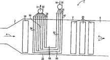
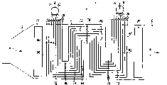
图1、2和3分别简化表示平卧式结构的蒸汽发生器纵剖面。Figures 1, 2 and 3 respectively simplify the longitudinal section of the steam generator with horizontal structure.
在所有的附图中相同的部分采用相同的附图标记。The same parts are provided with the same reference numerals in all figures.
按图1、2或3的蒸汽发生器1、1′、1″以废热蒸汽发生器的形式连接在未进一步表示的燃气轮机下游的废气侧。蒸汽发生器1、1′、1″各有一外壁2,该外壁构成一个可被来自燃气轮机的废热燃气沿近似水平的用箭头4示意表示的燃气方向x流过的燃气通道6。在该燃气通道6中设有一些按连续加热原理设计的加热面,亦称为连续加热面8、10或12。在按图1、2和3的实施方式中仅分别表示了一个连续加热面8、10或12,但也可以设置大量的连续加热面。The
由连续加热面8、10或12构成的汽化系统中可分别被加入流动介质W,该流动介质在一次性通过各连续加热面8、10或12时汽化,并在从连续加热面8、10或12排出时作为蒸汽D被排出,且通常为了进一步过热被输入过热加热面。由各连续加热面8、10或12构成的汽化系统分别连接在图中未进一步表示的一汽轮机水汽循环中。在汽轮机水汽循环内除各汽化系统外还连接另一些在图1至3中分别示意表示的加热面20。加热面20可例如涉及过热器、中压汽化器、低压汽化器和/或预热器。In the vaporization system made up of
按图1的蒸汽发生器1连续加热面8包括管束形式的多根为流过流动介质W并联的蒸汽发生器管22。沿燃气方向x看多根蒸汽发生器管22是并列的。图中仅用附图标记22表示出了如此并列的蒸汽发生器管22中的一个。沿流动介质流向分别在如此并列的蒸汽发生器管22的上游连接一公共的分配器26以及在其下游连接一公共的出口收集器28。在这里,各分配器26本身在进口侧与一主分配器30连接,以及出口收集器28在出口侧连接在一公共的主收集器32上。The continuous heating surface 8 of the
连续加热面8设计为适合供给蒸汽发生器管22比较低的质量流量密度,其中蒸汽发生器管22有一种自然循环特性。按照这种自然循环特性,同一连续加热面8中的与另一根蒸汽发生器管22相比受到更多加热的蒸汽发生器管22具有一个与该另一蒸汽发生器管22相比更大的流动介质W流量。为了能采取特别简单的结构措施以特别可靠的方式保证这一点,连续加热面8包括两个在流动介质侧串联的部分。其中连续加热面8的每根蒸汽发生器管22在第一部分中包括一个近似垂直布置可被流动介质W沿向下方向流过的下降管段34。每根蒸汽发生器管22在第二部分中包括一个沿流动介质流向连接在下降管段34下游的、近似垂直布置和可被流动介质W沿向上方向流过的上升管段36。The continuous heating surface 8 is designed to be suitable for supplying relatively low mass flow densities of the steam generator tubes 22, which have a natural circulation characteristic. According to this natural circulation characteristic, the steam generator tube 22 that is heated more than the other steam generator tube 22 in the same continuous heating surface 8 has a larger diameter than the other steam generator tube 22. The flow medium W flow rate. In order to be able to ensure this in a particularly reliable manner by taking particularly simple structural measures, the continuous heating surface 8 consists of two parts connected in series on the flow medium side. Each steam generator tube 22 of the continuous heating surface 8 includes in the first part an approximately vertically arranged downcomer section 34 through which the flow medium W can flow in a downward direction. Each steam generator tube 22 includes in the second part an ascending pipe section 36 connected downstream of the descending pipe section 34 along the flow direction of the flow medium, arranged approximately vertically and through which the flow medium W can flow in an upward direction.
上升管段36与配属于它的下降管段34在这里通过一溢流段38连接。在此实施方式中,溢流段38在燃气通道6内部延伸,以及为了在空间上固定,穿过设在燃气通道6内的孔板40导引。虽然孔板导致在燃气通道6内可供燃气用的流通截面局部变窄;但应强调指出,图1中没有按比例表示,所以由于孔板40使燃气流通截面相对变窄的程度是很小的。The riser section 36 is connected here to its associated downcomer section 34 via an overflow section 38 . In this embodiment, the overflow section 38 extends within the
作为替换方式,所述溢流段也可以在燃气通道6的外部,尤其在其下方导引。这尤其可适用于这样的情况:出自于结构和工作的原因应规定连续加热面8排水。这可以在溢流段38在燃气通道6外部导引时通过连接在溢流段上的排水收集器实现。在这种情况下,排水收集器优选地在空间上设在下降管段附近,所以无阻碍地保持加热管段因热膨胀所需的可运动性。Alternatively, the overflow section can also be guided outside the
如图1所示,连续加热面8的每根蒸汽发生器管22有一种近似U形的形状,其中,U形的边由下降管段34和上升管段36构成,之间的连接弧段则由溢流段38构成。在如此设计的蒸汽发生器管22中,在下降管段34的区域内的流动介质W的高度压力势能与在上升管段36的区域内相反,产生一种促进流动和不阻碍流动的压力势能。换句话说:处于下降管段34内未汽化的流动介质W的水柱“推进”有关蒸汽发生器管22的流动,而不是阻碍流动。由此,此蒸汽发生器管22在总体上看有比较低的压力损失。As shown in Figure 1, each steam generator pipe 22 of continuous heating surface 8 has a kind of approximate U shape, and wherein, the limit of U shape is made of descending pipe section 34 and ascending pipe section 36, and the connection arc section between is then formed by An overflow section 38 is formed. In a steam generator tube 22 designed in this way, the height pressure potential of the flow medium W in the area of the downcomer section 34 is opposite to that in the area of the uplink section 36, resulting in a pressure potential that promotes flow and does not impede it. In other words: the water column of the unvaporized flow medium W in the downcomer section 34 "pushes" the flow of the associated steam generator tube 22 instead of hindering it. As a result, the steam generator tube 22 has a comparatively low pressure loss overall.
在近似U形的结构方式中,每根蒸汽发生器管22分别在其下降管段34的进口区内和在其上升管段36的出口区内,按悬挂的结构形式悬挂或固定在燃气通道6的盖上。通过其溢流段38互相连接的各自的下降管段34和各自的上升管段36在空间上看的下端则相反,它们在空间上不直接固定在燃气通道6内。因此,蒸汽发生器管这些部分的纵向膨胀没有损坏危险地得以容忍,其中,各溢流段38起膨胀弧的作用。蒸汽发生器管22的这种布局机械上有特别好的柔性以及面对出现的膨胀差在热应力方面是不敏感的。In the approximately U-shaped structure, each steam generator tube 22 is suspended or fixed on the
一根蒸汽发生器管22,尤其在其上升管段36内,更多地受到加热,首先在那里导致提高汽化率,在这种情况下,可通过对于蒸汽发生器管22的尺寸设计,使这种受到更多的加热能导致有更大流量的流动介质进入此受到更多加热的蒸汽发生器管22。A steam generator tube 22, in particular in its riser section 36, is heated more, which firstly leads to an increased vaporization rate there, in which case this can be achieved by dimensioning the steam generator tube 22. This more heated energy results in a greater flow of flow medium into the more heated steam generator tube 22 .
此外,连续加热面8不同管列24的蒸汽发生器管22按互相嵌套的多重U方式排列。为此,多根蒸汽发生器管22的上升管段36和下降管段34在燃气通道6内彼此按这样的方式相对定位,即,为一个沿燃气方向X看处于比较靠后的下降管段34配设一个沿燃气方向X看比较靠前的上升管段36。通过这种布局使一个受到比较强烈地加热的上升管段36与一个受到比较少加热的下降管段34连通。通过这种相对定位,还在管段24之间达到一种自动平衡的效果。也就是说,正是在受到比较强烈加热的处于更前方的上升管段36中,受到更多地加热会导致特别强烈的蒸汽的产生,并因而对附加供给流动介质W有特别强烈的需求。但正是这种受到强烈加热的上升管段36与一个受到比较弱地加热的下降管段34连接。这一下降管段由于在其中导引的流动介质W中加入比较少的热量,所以有特别大的促进流动的高度压力势能,因此,正是这种受到比较弱地加热的下降管段34特别适用于提供附加的比较冷的流动介质W供给量。In addition, the steam generator tubes 22 of different tube arrays 24 on the continuous heating surface 8 are arranged in a multiple U pattern nested with each other. For this purpose, the ascending pipe section 36 and the descending pipe section 34 of the plurality of steam generator pipes 22 are positioned relative to each other in the
尤其在此布局中,一根蒸汽发生器管22的一个设置得比较远的上升管段36受到更多的加热,会导致在下降管段34中促进流动的高度压力势能以特别大的程度超过与之配属的上升管段36内阻碍流动的高度压力势能,从而又附加地实现向该上升管段36更多地供给流动介质W。基于蒸汽发生器管22的这种特别突出的自然循环特征,使蒸汽发生器管面对局部受到不同的加热在特别大的程度上有一种自稳定的特性:一列蒸汽发生器管22受到更多地加热导致局部在此蒸汽发生器管22列内有更多的流动介质W供入,所以基于相应地增大的冷却作用,自动均衡相应的温度值。因此,在主收集器32内流入的新蒸汽的蒸汽参数与各流通的管列24无关地而特别均匀。Especially in this arrangement, a farther-disposed riser section 36 of a steam generator tube 22 is heated more, which leads to a particularly large excess of the height pressure potential energy in the downcomer section 34 which facilitates the flow. The high pressure potential energy of the flow is hindered in the associated riser section 36 , so that an increased supply of the flow medium W to this riser section 36 is additionally achieved. Based on this particularly prominent natural circulation feature of the steam generator tubes 22, the steam generator tube faces are locally subjected to different heating and have a self-stabilizing characteristic to a particularly large extent: a row of steam generator tubes 22 is subjected to more The ground heating results in an increased supply of flow medium W locally in this row of steam generator tubes 22 , so that the corresponding temperature values are equalized automatically due to a correspondingly increased cooling effect. The steam parameters of the live steam flowing in the
根据蒸汽发生器1、1′、1″的设计点或规定的工作点,由向下流过的汽化部分提供的促进流动的高度压力势能可以明显超过连接在下游的第二汽化部分阻碍流动的高度压力势能。因此根据设计点可比较有利地使第一汽化部分针对比较大的摩擦压力损失来设计。为此在按图1的蒸汽发生器1管列的上游,主分配器30与配属于它们的各分配器26之间,各连接一节流装置42,它尤其可设计为可调的。Depending on the design point or specified operating point of the
作为替换方案,在按图2的实施方式中,蒸汽发生器1′包括一个连续加热面10,它的蒸汽发生器管50在第一部分中同样各有一下降管段52,但沿流动介质流向在它下游分别连接多个为流过流动介质W互相并联的上升管段54。通过它将下降管段52分别与配属于下降管段的多个上升管段54连接起来的溢流段56,在本实施方式中仍在燃气通道6内部导引并固定在孔板58中。但需要时它们也可以铺设在燃气通道6外部。在按图2的实施方式中,沿流动介质的流向在每个下降管段52下游分别连接两个并联的上升管段54。在这里使用的管有相同的尺寸,所以在并联的上升管段54内用于流动介质W的自由的流动载面,是连接在它们上游的公共下降管段52流动截面两倍那么大。作为替换方案,在下降管段52内这种对摩擦压力损失的限制,在需要的情况下也可以通过适当的尺寸设计,尤其通过选择一个比较小的直径达到。As an alternative, in the embodiment according to FIG. 2, the steam generator 1' comprises a
在按图3的实施方式中的蒸汽发生器1″包括一个连续加热面12,它同样针对比较小的摩擦压力损失设计以及因而在比较小的质量流量密度的情况下特别适用于保证自然循环特征。但除此之外,蒸汽发生器1″的连续加热面12在其吸热能力方面与流过燃气通道6的燃气的温度剖面特别匹配。为此,构成连续加热面12的每一根蒸汽发生器管60分别包括多个(在本实施方式中为两个)沿流动介质流向交替串联的下降管段62、64和上升管段66、68。沿流动介质W流动方向看的第一下降管段62,在这里分别通过一个溢流段70与连接在其下游的第一上升管段66连接。此上升管段本身在出口侧通过另一溢流段72与连接在其下游的第二下降管段64连接。此第二下降管段64通过又一溢流段74连接在第二上升管段66上。所述三个溢流段70、72、74仍在燃气通道6内部导引并分别借助孔板76、78或80固定在燃气通道6的底部或盖的区域内。The
Claims (9)
Applications Claiming Priority (2)
| Application Number | Priority Date | Filing Date | Title |
|---|---|---|---|
| DE10127830A DE10127830B4 (en) | 2001-06-08 | 2001-06-08 | steam generator |
| DE10127830.6 | 2001-06-08 |
Publications (2)
| Publication Number | Publication Date |
|---|---|
| CN1526059A true CN1526059A (en) | 2004-09-01 |
| CN1289853C CN1289853C (en) | 2006-12-13 |
Family
ID=7687617
Family Applications (1)
| Application Number | Title | Priority Date | Filing Date |
|---|---|---|---|
| CNB028112822A Expired - Fee Related CN1289853C (en) | 2001-06-08 | 2002-05-27 | Steam generator |
Country Status (12)
| Country | Link |
|---|---|
| US (1) | US6868807B2 (en) |
| EP (1) | EP1393001A2 (en) |
| JP (1) | JP4443216B2 (en) |
| KR (1) | KR100718357B1 (en) |
| CN (1) | CN1289853C (en) |
| CA (1) | CA2449652C (en) |
| CZ (1) | CZ20033530A3 (en) |
| DE (1) | DE10127830B4 (en) |
| PL (1) | PL199124B1 (en) |
| RU (1) | RU2004100240A (en) |
| SK (1) | SK287649B6 (en) |
| WO (1) | WO2002101292A2 (en) |
Cited By (1)
| Publication number | Priority date | Publication date | Assignee | Title |
|---|---|---|---|---|
| CN103154611A (en) * | 2010-08-04 | 2013-06-12 | 西门子公司 | Forced-flow steam generator |
Families Citing this family (23)
| Publication number | Priority date | Publication date | Assignee | Title |
|---|---|---|---|---|
| US20080059330A1 (en) * | 2002-02-07 | 2008-03-06 | Micro Beef Technologies, Ltd. | Livestock management systems and methods |
| EP1443268A1 (en) * | 2003-01-31 | 2004-08-04 | Siemens Aktiengesellschaft | Steam generator |
| EP1512905A1 (en) * | 2003-09-03 | 2005-03-09 | Siemens Aktiengesellschaft | Once-through steam generator and method of operating said once-through steam generator |
| EP1512906A1 (en) | 2003-09-03 | 2005-03-09 | Siemens Aktiengesellschaft | Once-through steam generator of horizontal construction and method of operating said once-through steam generator |
| FR2872886B1 (en) * | 2004-07-09 | 2006-09-22 | Total Sa | METHOD AND DEVICE FOR GENERATING WATER VAPOR ADAPTED TO OXY-COMBUSTION |
| US6957630B1 (en) * | 2005-03-31 | 2005-10-25 | Alstom Technology Ltd | Flexible assembly of once-through evaporation for horizontal heat recovery steam generator |
| CN101310146B (en) * | 2005-07-19 | 2010-08-18 | 塞拉米克燃料电池有限公司 | Steam generator |
| AU2006272450B2 (en) * | 2005-07-19 | 2010-09-02 | Chaozhou Three-Circle (Group) Co., Ltd. | Steam generator |
| WO2009106563A2 (en) | 2008-02-26 | 2009-09-03 | Alstom Technology Ltd | Method for regulating a boiler and control circuit for a boiler |
| EP2194320A1 (en) * | 2008-06-12 | 2010-06-09 | Siemens Aktiengesellschaft | Method for operating a once-through steam generator and once-through steam generator |
| ES2582657T3 (en) * | 2008-09-08 | 2016-09-14 | Balcke-Dürr GmbH | Heat exchanger in modular construction mode |
| EP2180250A1 (en) * | 2008-09-09 | 2010-04-28 | Siemens Aktiengesellschaft | Continuous-flow steam generator |
| DE102009012321A1 (en) * | 2009-03-09 | 2010-09-16 | Siemens Aktiengesellschaft | Flow evaporator |
| DE102009012320A1 (en) * | 2009-03-09 | 2010-09-16 | Siemens Aktiengesellschaft | Flow evaporator |
| DE102009012322B4 (en) * | 2009-03-09 | 2017-05-18 | Siemens Aktiengesellschaft | Flow evaporator |
| EP2839213B1 (en) | 2012-01-17 | 2018-09-05 | General Electric Technology GmbH | Tube and baffle arrangement in a once-through horizontal evaporator |
| WO2013108215A2 (en) | 2012-01-17 | 2013-07-25 | Alstom Technology Ltd | Start-up system for a once-through horizontal evaporator |
| DE102012218542B4 (en) * | 2012-10-11 | 2016-07-07 | Siemens Aktiengesellschaft | Method for the flexible operation of a power plant |
| EP2843304A1 (en) * | 2013-08-29 | 2015-03-04 | Casale SA | A shell-and-tube apparatus for heat recovery from a hot process stream |
| US9739476B2 (en) * | 2013-11-21 | 2017-08-22 | General Electric Technology Gmbh | Evaporator apparatus and method of operating the same |
| DE102014206043B4 (en) * | 2014-03-31 | 2021-08-12 | Mtu Friedrichshafen Gmbh | Method for operating a system for a thermodynamic cycle with a multi-flow evaporator, control device for a system, system for a thermodynamic cycle with a multi-flow evaporator, and arrangement of an internal combustion engine and a system |
| HRP20240708T1 (en) | 2018-10-01 | 2024-08-16 | Header-coil Company A/S | Heat exchanger, such as for a solar power plant |
| CN110094709B (en) * | 2019-05-28 | 2024-04-26 | 上海锅炉厂有限公司 | Direct-current evaporator and design method thereof |
Family Cites Families (19)
| Publication number | Priority date | Publication date | Assignee | Title |
|---|---|---|---|---|
| US589553A (en) * | 1897-09-07 | Half to francis j | ||
| DE425717C (en) | 1924-01-31 | 1926-02-24 | Hugo Dornseif | Laying nest for chickens and like |
| US2699758A (en) * | 1946-02-02 | 1955-01-18 | Svenska Maskinverken Ab | Method of preheating combustion supporting air for steam generating plants |
| DE1176155B (en) * | 1959-02-28 | 1964-08-20 | Buckau Wolf Maschf R | Steep tube boiler with an upper, cooled projection on the rear wall |
| FR2443643A1 (en) * | 1978-12-06 | 1980-07-04 | Creusot Loire | HEATING APPARATUS PROVIDING WATER VAPOR AND HOT GAS |
| US4357907A (en) * | 1980-10-27 | 1982-11-09 | Rockwell International Corporation | Fluidized bed combustor with improved indirect heat exchanger units |
| JPS61186702A (en) * | 1985-02-14 | 1986-08-20 | 三菱重工業株式会社 | Exhaust gas boiler |
| US4685426A (en) * | 1986-05-05 | 1987-08-11 | The Babcock & Wilcox Company | Modular exhaust gas steam generator with common boiler casing |
| JPH0718525B2 (en) * | 1987-05-06 | 1995-03-06 | 株式会社日立製作所 | Exhaust gas boiler |
| DE58909259D1 (en) * | 1989-10-30 | 1995-06-29 | Siemens Ag | Continuous steam generator. |
| JPH03221702A (en) * | 1990-01-29 | 1991-09-30 | Toshiba Corp | Duplex type heat exchanger for waste heat recovery |
| BE1005793A3 (en) * | 1992-05-08 | 1994-02-01 | Cockerill Mech Ind Sa | INDUCED CIRCULATION HEAT RECOVERY BOILER. |
| DE19651678A1 (en) * | 1996-12-12 | 1998-06-25 | Siemens Ag | Steam generator |
| DE19651936C2 (en) * | 1996-12-14 | 2000-08-31 | Nem Bv | Continuous steam generator with a throttle cable for connection to a device emitting hot gas |
| DE19700350A1 (en) | 1997-01-08 | 1998-07-16 | Steinmueller Gmbh L & C | Continuous steam generator with gas flue and condenser heating surfaces |
| US6092490A (en) * | 1998-04-03 | 2000-07-25 | Combustion Engineering, Inc. | Heat recovery steam generator |
| US6019070A (en) | 1998-12-03 | 2000-02-01 | Duffy; Thomas E. | Circuit assembly for once-through steam generators |
| US6588379B2 (en) * | 2001-08-06 | 2003-07-08 | Bwx Technologies, Inc. | Multi-stream energy source steam generator system |
| US6557500B1 (en) * | 2001-12-05 | 2003-05-06 | Nooter/Eriksen, Inc. | Evaporator and evaporative process for generating saturated steam |
-
2001
- 2001-06-08 DE DE10127830A patent/DE10127830B4/en not_active Expired - Fee Related
-
2002
- 2002-05-27 EP EP02729915A patent/EP1393001A2/en not_active Withdrawn
- 2002-05-27 KR KR1020037016063A patent/KR100718357B1/en not_active Expired - Fee Related
- 2002-05-27 CN CNB028112822A patent/CN1289853C/en not_active Expired - Fee Related
- 2002-05-27 CZ CZ20033530A patent/CZ20033530A3/en unknown
- 2002-05-27 WO PCT/DE2002/001936 patent/WO2002101292A2/en not_active Ceased
- 2002-05-27 US US10/479,994 patent/US6868807B2/en not_active Expired - Fee Related
- 2002-05-27 SK SK1606-2003A patent/SK287649B6/en not_active IP Right Cessation
- 2002-05-27 CA CA002449652A patent/CA2449652C/en not_active Expired - Fee Related
- 2002-05-27 PL PL367197A patent/PL199124B1/en not_active IP Right Cessation
- 2002-05-27 JP JP2003504017A patent/JP4443216B2/en not_active Expired - Fee Related
- 2002-05-27 RU RU2004100240/06A patent/RU2004100240A/en not_active Application Discontinuation
Cited By (3)
| Publication number | Priority date | Publication date | Assignee | Title |
|---|---|---|---|---|
| CN103154611A (en) * | 2010-08-04 | 2013-06-12 | 西门子公司 | Forced-flow steam generator |
| CN103154611B (en) * | 2010-08-04 | 2016-03-16 | 西门子公司 | Forced once-through boiler |
| US9291344B2 (en) | 2010-08-04 | 2016-03-22 | Siemens Aktiengesellschaft | Forced-flow steam generator |
Also Published As
| Publication number | Publication date |
|---|---|
| DE10127830B4 (en) | 2007-01-11 |
| WO2002101292A2 (en) | 2002-12-19 |
| CZ20033530A3 (en) | 2004-04-14 |
| PL199124B1 (en) | 2008-08-29 |
| US6868807B2 (en) | 2005-03-22 |
| DE10127830A1 (en) | 2002-12-12 |
| RU2004100240A (en) | 2005-05-27 |
| JP4443216B2 (en) | 2010-03-31 |
| EP1393001A2 (en) | 2004-03-03 |
| KR100718357B1 (en) | 2007-05-14 |
| CN1289853C (en) | 2006-12-13 |
| SK287649B6 (en) | 2011-05-06 |
| JP2004529310A (en) | 2004-09-24 |
| CA2449652A1 (en) | 2002-12-19 |
| CA2449652C (en) | 2007-12-11 |
| PL367197A1 (en) | 2005-02-21 |
| SK16062003A3 (en) | 2005-02-04 |
| WO2002101292A3 (en) | 2003-10-02 |
| KR20040011530A (en) | 2004-02-05 |
| US20040149239A1 (en) | 2004-08-05 |
Similar Documents
| Publication | Publication Date | Title |
|---|---|---|
| CN1289853C (en) | Steam generator | |
| JP4549868B2 (en) | Waste heat boiler | |
| CN1856680B (en) | Method for starting a continuous steam generator and continuous steam generator for carrying out said method | |
| CN107002987B (en) | Direct-current vertical tube type supercritical evaporator coil for HRSG | |
| US9267678B2 (en) | Continuous steam generator | |
| CN1122777C (en) | Boiler | |
| CN102345858A (en) | Solar cavity-type heat absorber capable of generating overheated steam | |
| KR101663850B1 (en) | Continuous evaporator | |
| RU2396486C1 (en) | Reactor feed water circuit with fluidised bed and reactor with fluidised bed with such feed water circuit | |
| CN102245966B (en) | Continuous steam generator | |
| CN102753891B (en) | Continuous evaporator | |
| US12442529B2 (en) | Circulating fluidized bed boiler | |
| CN1853071A (en) | Horizontally constructed continuous steam generator and method for the operation thereof | |
| CN1016887B (en) | Upflow / downflow heated tube circulating system | |
| JP7542646B2 (en) | Apparatus and method for supporting the sidewalls of a vertical flue gas passage in a thermal steam generator | |
| RU2800205C1 (en) | Structure and method for providing support for side screen of vertical gas duct for flue gases in thermal power steam generator |
Legal Events
| Date | Code | Title | Description |
|---|---|---|---|
| C06 | Publication | ||
| PB01 | Publication | ||
| C10 | Entry into substantive examination | ||
| SE01 | Entry into force of request for substantive examination | ||
| C14 | Grant of patent or utility model | ||
| GR01 | Patent grant | ||
| C17 | Cessation of patent right | ||
| CF01 | Termination of patent right due to non-payment of annual fee |
Granted publication date: 20061213 Termination date: 20130527 |