CN1526061A - Refrigeration cycle device - Google Patents
Refrigeration cycle device Download PDFInfo
- Publication number
- CN1526061A CN1526061A CNA028100395A CN02810039A CN1526061A CN 1526061 A CN1526061 A CN 1526061A CN A028100395 A CNA028100395 A CN A028100395A CN 02810039 A CN02810039 A CN 02810039A CN 1526061 A CN1526061 A CN 1526061A
- Authority
- CN
- China
- Prior art keywords
- refrigerant
- oil
- evaporator
- heat transfer
- radiator
- Prior art date
- Legal status (The legal status is an assumption and is not a legal conclusion. Google has not performed a legal analysis and makes no representation as to the accuracy of the status listed.)
- Withdrawn
Links
Images


Classifications
-
- F—MECHANICAL ENGINEERING; LIGHTING; HEATING; WEAPONS; BLASTING
- F25—REFRIGERATION OR COOLING; COMBINED HEATING AND REFRIGERATION SYSTEMS; HEAT PUMP SYSTEMS; MANUFACTURE OR STORAGE OF ICE; LIQUEFACTION SOLIDIFICATION OF GASES
- F25B—REFRIGERATION MACHINES, PLANTS OR SYSTEMS; COMBINED HEATING AND REFRIGERATION SYSTEMS; HEAT PUMP SYSTEMS
- F25B39/00—Evaporators; Condensers
- F25B39/04—Condensers
-
- F—MECHANICAL ENGINEERING; LIGHTING; HEATING; WEAPONS; BLASTING
- F28—HEAT EXCHANGE IN GENERAL
- F28F—DETAILS OF HEAT-EXCHANGE AND HEAT-TRANSFER APPARATUS, OF GENERAL APPLICATION
- F28F1/00—Tubular elements; Assemblies of tubular elements
- F28F1/10—Tubular elements and assemblies thereof with means for increasing heat-transfer area, e.g. with fins, with projections, with recesses
- F28F1/40—Tubular elements and assemblies thereof with means for increasing heat-transfer area, e.g. with fins, with projections, with recesses the means being only inside the tubular element
-
- F—MECHANICAL ENGINEERING; LIGHTING; HEATING; WEAPONS; BLASTING
- F28—HEAT EXCHANGE IN GENERAL
- F28D—HEAT-EXCHANGE APPARATUS, NOT PROVIDED FOR IN ANOTHER SUBCLASS, IN WHICH THE HEAT-EXCHANGE MEDIA DO NOT COME INTO DIRECT CONTACT
- F28D1/00—Heat-exchange apparatus having stationary conduit assemblies for one heat-exchange medium only, the media being in contact with different sides of the conduit wall, in which the other heat-exchange medium is a large body of fluid, e.g. domestic or motor car radiators
- F28D1/02—Heat-exchange apparatus having stationary conduit assemblies for one heat-exchange medium only, the media being in contact with different sides of the conduit wall, in which the other heat-exchange medium is a large body of fluid, e.g. domestic or motor car radiators with heat-exchange conduits immersed in the body of fluid
- F28D1/04—Heat-exchange apparatus having stationary conduit assemblies for one heat-exchange medium only, the media being in contact with different sides of the conduit wall, in which the other heat-exchange medium is a large body of fluid, e.g. domestic or motor car radiators with heat-exchange conduits immersed in the body of fluid with tubular conduits
- F28D1/053—Heat-exchange apparatus having stationary conduit assemblies for one heat-exchange medium only, the media being in contact with different sides of the conduit wall, in which the other heat-exchange medium is a large body of fluid, e.g. domestic or motor car radiators with heat-exchange conduits immersed in the body of fluid with tubular conduits the conduits being straight
- F28D1/0535—Heat-exchange apparatus having stationary conduit assemblies for one heat-exchange medium only, the media being in contact with different sides of the conduit wall, in which the other heat-exchange medium is a large body of fluid, e.g. domestic or motor car radiators with heat-exchange conduits immersed in the body of fluid with tubular conduits the conduits being straight the conduits having a non-circular cross-section
- F28D1/05366—Assemblies of conduits connected to common headers, e.g. core type radiators
- F28D1/05391—Assemblies of conduits connected to common headers, e.g. core type radiators with multiple rows of conduits or with multi-channel conduits combined with a particular flow pattern, e.g. multi-row multi-stage radiators
-
- F—MECHANICAL ENGINEERING; LIGHTING; HEATING; WEAPONS; BLASTING
- F28—HEAT EXCHANGE IN GENERAL
- F28F—DETAILS OF HEAT-EXCHANGE AND HEAT-TRANSFER APPARATUS, OF GENERAL APPLICATION
- F28F1/00—Tubular elements; Assemblies of tubular elements
- F28F1/02—Tubular elements of cross-section which is non-circular
- F28F1/022—Tubular elements of cross-section which is non-circular with multiple channels
-
- F—MECHANICAL ENGINEERING; LIGHTING; HEATING; WEAPONS; BLASTING
- F25—REFRIGERATION OR COOLING; COMBINED HEATING AND REFRIGERATION SYSTEMS; HEAT PUMP SYSTEMS; MANUFACTURE OR STORAGE OF ICE; LIQUEFACTION SOLIDIFICATION OF GASES
- F25B—REFRIGERATION MACHINES, PLANTS OR SYSTEMS; COMBINED HEATING AND REFRIGERATION SYSTEMS; HEAT PUMP SYSTEMS
- F25B2309/00—Gas cycle refrigeration machines
- F25B2309/06—Compression machines, plants or systems characterised by the refrigerant being carbon dioxide
- F25B2309/061—Compression machines, plants or systems characterised by the refrigerant being carbon dioxide with cycle highest pressure above the supercritical pressure
-
- F—MECHANICAL ENGINEERING; LIGHTING; HEATING; WEAPONS; BLASTING
- F25—REFRIGERATION OR COOLING; COMBINED HEATING AND REFRIGERATION SYSTEMS; HEAT PUMP SYSTEMS; MANUFACTURE OR STORAGE OF ICE; LIQUEFACTION SOLIDIFICATION OF GASES
- F25B—REFRIGERATION MACHINES, PLANTS OR SYSTEMS; COMBINED HEATING AND REFRIGERATION SYSTEMS; HEAT PUMP SYSTEMS
- F25B9/00—Compression machines, plants or systems, in which the refrigerant is air or other gas of low boiling point
- F25B9/002—Compression machines, plants or systems, in which the refrigerant is air or other gas of low boiling point characterised by the refrigerant
- F25B9/008—Compression machines, plants or systems, in which the refrigerant is air or other gas of low boiling point characterised by the refrigerant the refrigerant being carbon dioxide
Landscapes
- Engineering & Computer Science (AREA)
- Physics & Mathematics (AREA)
- Thermal Sciences (AREA)
- Mechanical Engineering (AREA)
- General Engineering & Computer Science (AREA)
- Geometry (AREA)
- Lubricants (AREA)
Abstract
Description
技术领域technical field
本发明涉及作为主体制冷剂使用二氧化碳(以下称为CO2)的冷冻机和空调机等的冷冻循环装置。The present invention relates to refrigeration cycle devices such as refrigerators and air conditioners using carbon dioxide (hereinafter referred to as CO 2 ) as a main refrigerant.
背景技术Background technique
目前,在空调机、冰箱、冷冻库、自动销售机、加热泵热水器等的冷冻循环装置的制冷剂中,从物性稳定、便于处理的观点出发,使用的是含氯而不含氢的氟碳类(以下称为CFC)以及含氯和氢的氟烃类(以下称为HCFC)。At present, fluorocarbons containing chlorine but not hydrogen are used as refrigerants in refrigeration cycle equipment such as air conditioners, refrigerators, freezers, vending machines, heat pump water heaters, etc., from the viewpoint of stable physical properties and easy handling. (hereinafter referred to as CFC) and fluorocarbons containing chlorine and hydrogen (hereinafter referred to as HCFC).
然而,CFC制冷剂和HCFC制冷剂因具有促进臭氧层破坏的性质,故提出有采用分子构造中不含氯而含氢的氟化烃类(以下称为HFC)来作为替代制冷剂的提案。又,CFC制冷剂、HCFC制冷剂、HFC制冷剂因具有促进地球温暖化的性质,故提出有采用对地球温暖化影响极小的自然制冷剂来作为替代制冷剂的提案。However, since CFC refrigerants and HCFC refrigerants have the property of promoting the destruction of the ozone layer, it has been proposed to use fluorinated hydrocarbons (hereinafter referred to as HFCs) containing hydrogen in molecular structure without chlorine as alternative refrigerants. In addition, since CFC refrigerants, HCFC refrigerants, and HFC refrigerants have the property of promoting global warming, it has been proposed to use natural refrigerants that have little influence on global warming as alternative refrigerants.
但是,即使是自然制冷剂,因碳化氢类(以下称为HC)具有强可燃性,故存在着引火、爆炸的危险性,又由于铵制冷剂具有毒性,故存在着泄漏时产生危险的问题,由此,对非燃性、无毒性且成本低的CO2制冷剂的使用正在研讨之中。However, even with natural refrigerants, hydrocarbons (hereinafter referred to as HC) are highly flammable, so there is a risk of ignition and explosion, and because ammonium refrigerants are toxic, there is a problem of danger in the event of leakage. , and thus, the use of nonflammable, nontoxic, and low-cost CO2 refrigerants is under investigation.
使用这种CO2制冷剂的冷冻循环装置因CO2制冷剂的临界温度是31℃,故成为在超临界区域中使用高压侧线路的结构,普通的冷冻循环装置是将制冷剂压缩进行升压的压缩机、需要时将四通阀、冷却制冷剂的放热器、减压制冷剂的毛细管和膨胀阀等的减压器、制冷剂蒸发气化的蒸发器等进行配管连接而成,通过使制冷剂在其内部循环,起着冷却或加热作用。The refrigeration cycle device using this CO 2 refrigerant has a structure that uses a high-pressure side line in the supercritical region because the critical temperature of CO 2 refrigerant is 31°C, and a general refrigeration cycle device compresses the refrigerant to increase the pressure. Compressor, if necessary, four-way valve, heat radiator for cooling refrigerant, pressure reducer such as capillary tube for decompressing refrigerant, expansion valve, etc., evaporator for evaporating and vaporizing refrigerant, etc. The refrigerant circulates inside it for cooling or heating.
作为使用CO2制冷剂的冷冻循环装置的放热器和蒸发器中使用的热交换器,采用称为微型管热交换器的热交换器。微型管热交换器由内部形成有多个贯通小孔(制冷剂流路)的扁平管和增大与配置于该扁平管间的外部流体(如空气)的传热面积用的散热片所构成。贯通小孔的剖面形状是圆形,孔径约为1mm。As the heat exchanger used in the radiator and evaporator of the refrigeration cycle device using CO2 refrigerant, a heat exchanger called a micro tube heat exchanger is adopted. The micro tube heat exchanger is composed of flat tubes with a plurality of through holes (refrigerant flow paths) formed inside, and fins for increasing the heat transfer area between the flat tubes and the external fluid (such as air) . The cross-sectional shape of the through hole is circular, and the diameter of the hole is about 1mm.
作为CO2制冷剂用的冷冻机油,从润滑性优良的观点出发,大多采用矿物油(参照文献:B.E.Fagerli著「Development and Experiment with a HermeticCO2 Compressor」Proceeding of the 1996 International EngineeringConference at Purdue,229-234)。As refrigerating machine oil for CO 2 refrigerant, mineral oil is mostly used from the viewpoint of excellent lubricity (reference document: "Development and Experiment with a Hermetic CO 2 Compressor" by BEFagerli, Proceeding of the 1996 International Engineering Conference at Purdue, 229-234 ).
然而,因矿物油是非极性油,故与CO2制冷剂为非相溶,与制冷剂一起从压缩机向循环中吐出的冷冻机油在放热器和蒸发器的制冷剂流路中以油滴状或作为油膜环状覆盖于管内壁的形态流动。由此引起热传递的障碍和导致压力损失增大,成为热交换器尺寸增大和效率降低的原因。特别是在非超临界区域的蒸发器中,因冷冻机油而造成的热传递明显下降。However, since mineral oil is a non-polar oil, it is immiscible with CO 2 refrigerant, and the refrigerating machine oil discharged from the compressor into the cycle together with the refrigerant becomes oil in the refrigerant flow path of the radiator and evaporator. Flow in the shape of drops or as an oil film covering the inner wall of the pipe in a ring shape. As a result, heat transfer is hindered and pressure loss is increased, which causes an increase in the size of the heat exchanger and a decrease in efficiency. Especially in evaporators in the non-supercritical region, the heat transfer due to refrigeration oil is significantly reduced.
又,使用微型管热交换器时,因制冷剂流路是孔径约1mm的非常细的传热管,故与使用以往对HFC制冷剂而使用的具有管径约5mm大小的剖面积的制冷剂流路相比,本发明者发现了对于因管内壁上形成的油膜和油滴所造成的热传递障碍以及压力损失的增大效果很大。其内容详述如下。In addition, when using a microtube heat exchanger, since the refrigerant flow path is a very thin heat transfer tube with a diameter of about 1 mm, it is different from the refrigerant with a cross-sectional area of about 5 mm in diameter that is conventionally used for HFC refrigerants. Compared with the flow path, the present inventors have found that the oil film and oil droplets formed on the inner wall of the tube have a large effect on heat transfer obstruction and increase in pressure loss. Its content is detailed below.
图6和图7分别是使用将相当直径1.2mm的微型管作为制冷剂流路的扁平管的蒸发器中的蒸发能力和压力损失的特性图。对于CO2制冷剂,冷冻机油采用非相溶的非极性油即矿物油。横轴是制冷剂循环量除以油(冷冻机油)循环量的油循环率。使用非相溶油时,可以看出通过增大油循环率,热传递率明显下降,压力损失明显增大。6 and 7 are characteristic diagrams of evaporating capacity and pressure loss in an evaporator using a flat tube having a microtube having an equivalent diameter of 1.2 mm as a refrigerant flow path, respectively. For CO2 refrigerants, non-polar oils that are immiscible, that is, mineral oils, are used as refrigeration oil. The horizontal axis represents the oil circulation rate obtained by dividing the refrigerant circulation amount by the oil (refrigeration machine oil) circulation amount. When immiscible oil is used, it can be seen that by increasing the oil circulation rate, the heat transfer rate decreases significantly and the pressure loss increases significantly.
按照下述的相关公式从含有图6和图7所示数据的各种实验数据中求出的计算值,能良好地与油和CO2制冷剂循环时的扁平管的蒸发热传递率及压力损失的值保持一致。Calculated values obtained from various experimental data including the data shown in Fig. 6 and Fig. 7 according to the following correlation formula, the evaporative heat transfer rate and pressure of the flat tube when circulating with oil and CO 2 refrigerant are good. The value of the loss remains the same.
即,对于蒸发热传递率是作为管内蒸发热传递率的相关式将一般所知的Lyu-Winterton的相关式考虑了对核沸腾热传递率的油混合有影响的参数Kfh来进行修正,对于强制对流热传递率则是进行将液的物性值改变为制冷剂与油的混合物的值的修正。That is, the evaporation heat transfer rate is a correlation formula of the evaporation heat transfer rate in the tube. The commonly known Lyu-Winterton correlation formula is corrected by taking into account the parameter Kfh that affects the nucleate boiling heat transfer rate. The convective heat transfer rate is corrected by changing the physical property value of the liquid to the value of the mixture of the refrigerant and the oil.
(数式1)(Formula 1)
h=a·{(E·h1)2+(S·h pool)2}0.5 (公式1)h=a·{(E·h1) 2 +(S·h pool) 2 } 0.5 (Formula 1)
(数式2)(Formula 2)
h pool=55·Pr0.12·{-logPr-0.55·M-0.5·q0.67·Kfh (公式2)h pool=55·Pr 0.12 ·{-logPr -0.55 ·M -0.5 ·q 0.67 ·Kfh (Formula 2)
其中,h是蒸发热传递率、a是常数、h1是只视为液层流动时的强制对流热传递率、h pool是沸腾热传递率、E、S分别是强制对流、核沸腾程度的参数。Among them, h is the evaporation heat transfer rate, a is a constant, h1 is the forced convection heat transfer rate when only liquid layer flow is considered, h pool is the boiling heat transfer rate, E and S are the parameters of forced convection and nucleate boiling respectively .
又,对于压力损失,作为二相流压力损失的相关式,一般是在已知的Lockhart-Martnelli的相关式中进行将液的物性值改变为制冷剂与油的混合物值的修正。Also, for the pressure loss, as a correlation expression of the two-phase flow pressure loss, correction is generally performed by changing the physical property value of the liquid to the value of the mixture of the refrigerant and the oil in the known Lockhart-Martnelli correlation expression.
(数式3)(Formula 3)
ΔP=φ2·ΔPf·KfP (公式3)ΔP=φ 2 ·ΔPf·KfP (Formula 3)
其中,φ是Martnelli的参数、ΔPf是只视为液相流动时的压力损失、Kfp是修正参数。Among them, φ is the parameter of Martnelli, ΔPf is the pressure loss when only considering the liquid phase flow, and Kfp is the correction parameter.
图8是由上述相关公式求出的CO2制冷剂的蒸发热传递率和压力损失的特性图(代表例)。横轴是制冷剂循环量除以油循环量的油循环率。又,纵轴是用油循环率为0%时的压力损失作为100时的压力损失之比除以油循环率为0%时的热传递率作为100时的热传递率之比的值的百分率。即,油循环率为0%时是100,因油循环率增大,越是加大热传递率的下降且/或增大压力损失的增加,则数值越小于100。Fig. 8 is a characteristic diagram (representative example) of the evaporation heat transfer rate and pressure loss of the CO 2 refrigerant obtained from the above correlation formula. The horizontal axis represents the oil circulation rate obtained by dividing the refrigerant circulation amount by the oil circulation amount. Also, the vertical axis is the percentage of the value obtained by dividing the ratio of the pressure loss when the oil circulation rate is 0% as 100 by the ratio of the heat transfer rate when the oil circulation rate is 0% as 100 . That is, when the oil circulation rate is 0%, it is 100, and as the oil circulation rate increases, the lower the heat transfer rate and/or the larger the pressure loss increase, the smaller the value becomes.
图8也表示了水力相当直径De不同的细管的特性,水力相当直径De越小,则热传递率的下降越大、且/或压力损失的增加越多。FIG. 8 also shows the characteristics of thin tubes with different hydraulic equivalent diameters De. The smaller the hydraulic equivalent diameter De is, the greater the decrease in heat transfer rate and/or the greater the increase in pressure loss.
下面对其作进一步详细探讨,图9为表示油循环率从0增至4%场合的(热传递率/压力损失)减少率与水力相当直径De的关系。当水力相当直径De从约1mm进一步减少时,可以看出(热传递率/压力损失)减少率急剧增大。即,若当水力相当直径De从约1mm进一步变细,则因受非相溶的油的影响,管内壁形成油膜或者油滴在管内飞散,大大降低热传递率、且/或压力损失的增加变大。It will be further discussed in detail below. Figure 9 shows the relationship between the (heat transfer rate/pressure loss) reduction rate and the hydraulic equivalent diameter De when the oil circulation rate increases from 0 to 4%. When the hydraulic equivalent diameter De is further reduced from about 1 mm, it can be seen that the (heat transfer rate/pressure loss) reduction rate increases sharply. That is, if the hydraulically equivalent diameter De is further reduced from about 1 mm, due to the influence of immiscible oil, an oil film is formed on the inner wall of the tube or oil droplets are scattered in the tube, which greatly reduces the heat transfer rate and/or increases the pressure loss. get bigger.
发明内容Contents of the invention
本发明就为解决上述以往的冷冻循环的课题,其目的在于,提供一种小型、高效率的使用CO2制冷剂的冷冻循环装置。The present invention solves the above-mentioned problems of the conventional refrigeration cycle, and an object of the present invention is to provide a small-sized, high-efficiency refrigeration cycle apparatus using CO 2 refrigerant.
本发明第1技术方案的冷冻循环装置,包括:压缩二氧化碳(CO2)制冷剂用的压缩机;对所述压缩机中升压的制冷剂进行冷却的放热器;配置在离所述放热器的制冷剂下游侧、对冷却的制冷剂进行减压膨胀的减压器;以及对由所述减压器减压的制冷剂进行加热的蒸发器,The refrigerating cycle device of the first technical solution of the present invention includes: a compressor for compressing carbon dioxide (CO 2 ) refrigerant; a heat radiator for cooling the refrigerant boosted in the compressor; a refrigerant downstream side of the heater, a pressure reducer that decompresses and expands the cooled refrigerant; and an evaporator that heats the refrigerant decompressed by the pressure reducer,
所述放热器及/或所述蒸发器的制冷剂流路是1mm或1mm以下的细管,The refrigerant flow path of the radiator and/or the evaporator is a thin tube of 1 mm or less,
使用以与所述CO2制冷剂相溶的有极性油作为主体而组成的冷冻机油。A refrigerating machine oil composed mainly of a polar oil compatible with the CO 2 refrigerant is used.
本发明第2技术方案是在本发明第1技术方案的冷冻循环装置中,所述制冷剂流路是扁平管中形成的多个贯通小孔。According to a second aspect of the present invention, in the refrigeration cycle apparatus according to the first aspect of the present invention, the refrigerant flow path is a plurality of through-holes formed in a flat tube.
本发明第3技术方案是在本发明第1技术方案的冷冻循环装置中,作为所述冷冻机油,使用聚醚油、聚酯油、聚二醇油、聚碳酸酯油或者这些油的混合油。According to a third aspect of the present invention, in the refrigerating cycle apparatus according to the first aspect of the present invention, polyether oil, polyester oil, polyglycol oil, polycarbonate oil, or a mixed oil of these oils is used as the refrigerating machine oil. .
本发明第4技术方案是在本发明第1技术方案的冷冻循环装置中,所述冷冻机油中含有的水分量为100ppm以下。According to a fourth aspect of the present invention, in the refrigeration cycle apparatus according to the first aspect of the present invention, the amount of water contained in the refrigerating machine oil is 100 ppm or less.
本发明第5技术方案是在本发明第2技术方案的冷冻循环装置中,所述贯通小孔是内面形成有槽的带内面槽小孔。According to a fifth aspect of the present invention, in the refrigerating cycle apparatus according to the second aspect of the present invention, the through-holes are small holes with inner surface grooves formed with grooves on their inner surfaces.
本发明第6技术方案是在本发明第5技术方案的冷冻循环装置中,所述带内面槽小孔的槽形状是梯形。According to a sixth technical solution of the present invention, in the refrigerating cycle device according to the fifth technical solution of the present invention, the groove shape of the small hole with inner grooves is trapezoidal.
附图的简单说明A brief description of the drawings
图1为本发明实施例1中的冷冻循环装置的概略结构图。Fig. 1 is a schematic configuration diagram of a refrigeration cycle apparatus in Example 1 of the present invention.
图2为本发明实施例1中使用的热交换器的结构图。Fig. 2 is a structural diagram of a heat exchanger used in Example 1 of the present invention.
图3为本发明实施例1的热交换器中使用的传热管的结构图。Fig. 3 is a structural view of the heat transfer tube used in the heat exchanger according to
图4为本发明实施例2的冷冻循环装置中使用的热交换器的传热管要部放大结构图。Fig. 4 is an enlarged structural view of a main part of a heat transfer tube of a heat exchanger used in a refrigerating cycle apparatus according to Example 2 of the present invention.
图5为本发明实施例3的冷冻循环装置中使用的热交换器的传热管要部放大结构图。Fig. 5 is an enlarged structural view of a main part of a heat transfer tube of a heat exchanger used in a refrigeration cycle apparatus according to Example 3 of the present invention.
图6为使用将相当直径1.2mm的微型管作为制冷剂流路的扁平管的蒸发器中相对于油循环率的蒸发能力的特性图。6 is a characteristic diagram of evaporating capacity with respect to an oil circulation rate in an evaporator using a flat tube having a microtube having an equivalent diameter of 1.2 mm as a refrigerant flow path.
图7为使用将相当直径1.2mm的微型管作为制冷剂流路的扁平管的蒸发器中相对于油循环率的压力损失的特性图。Fig. 7 is a characteristic diagram of pressure loss with respect to oil circulation rate in an evaporator using a flat tube having a microtube having an equivalent diameter of 1.2 mm as a refrigerant flow path.
图8为有关水力相当直径De不同的细管的特性图。Fig. 8 is a characteristic diagram of different thin tubes with respect to the hydraulic equivalent diameter De.
图9为表示油循环率从0增至4%场合的(热传递率/压力损失)减少率与水力相当直径De的关系图。Fig. 9 is a graph showing the relationship between the decrease rate of (heat transfer rate/pressure loss) and the hydraulic equivalent diameter De when the oil circulation rate increases from 0 to 4%.
图10为进行压热试验场合的试验后的PET树脂的拉伸强度特性图。Fig. 10 is a graph showing the tensile strength characteristics of PET resin after the test in the case of an autoclave test.
图11为进行压热试验场合的试验后的PET树脂的伸长特性图。Fig. 11 is a graph showing the elongation characteristics of the PET resin after the test in the case of the autoclave test.
(符号的说明)(explanation of symbols)
1、31、41扁平管1, 31, 41 flat tube
2贯通小孔2 through holes
3热交换器3 heat exchangers
9散热片9 heat sink
11压缩机11 compressors
12放热器12 Radiator
13减压器13 pressure reducer
14蒸发器14 evaporator
15油分离器15 oil separator
16辅助热交换器16 auxiliary heat exchanger
17副减压器17 pressure reducers
32、42带内面槽小孔32, 42 small hole with inner groove
具体实施方式Detailed ways
下面参照附图说明本发明的实施例。Embodiments of the present invention will be described below with reference to the drawings.
(实施例1)(Example 1)
图1为本发明实施例1中的冷冻循环装置的概略结构图。图2为放热器和蒸发器中使用的热交换器的结构图。又,图3为上述热交换器中使用的传热管的结构图。Fig. 1 is a schematic configuration diagram of a refrigeration cycle apparatus in Example 1 of the present invention. Figure 2 is a block diagram of the heat exchanger used in the radiator and evaporator. Moreover, FIG. 3 is a block diagram of a heat transfer tube used in the above-mentioned heat exchanger.
图1至图3中,11是压缩机,12是形成于扁平管1中的、作为制冷剂流路的具有多个贯通小孔2的放热器,13是减压器,14是形成于扁平管1中的、作为制冷剂流路的具有多个贯通小孔2的蒸发器,通过将这些构件进行配管连接形成闭回路,并构成CO2制冷剂沿图中的箭头方向进行循环的冷冻循环。1 to 3, 11 is a compressor, 12 is a heat radiator formed in a
并且,具有辅助热交换器16,该辅助热交换器16用于在从放热器12的出口至减压器13的入口的制冷剂流路即放热侧制冷剂流路和从蒸发器14的出口至压缩机11的吸入部的制冷剂流路即蒸发侧制冷剂流路中进行热交换。In addition, an auxiliary heat exchanger 16 is provided for the refrigerant flow path from the outlet of the heat radiator 12 to the inlet of the pressure reducer 13 , that is, the heat release side refrigerant flow path and the refrigerant flow path from the evaporator 14 . Heat exchange is performed in the evaporating side refrigerant flow path that is the refrigerant flow path from the outlet of the compressor 11 to the suction part of the compressor 11 .
又,在压缩机11与放热器12间具有油分离器15。由油分离器15分离的冷冻机油通过副减压器17并经由与压缩机11配管连接的辅助路径18返回到压缩机11。未由油分离器15分离的冷冻机油与制冷剂一起流向冷冻循环的放热器12及蒸发器14。Moreover, an oil separator 15 is provided between the compressor 11 and the radiator 12 . The refrigerating machine oil separated by the oil separator 15 returns to the compressor 11 through the auxiliary path 18 connected to the compressor 11 through the sub pressure reducer 17 . The refrigerating machine oil not separated by the oil separator 15 flows to the radiator 12 and the evaporator 14 of the refrigerating cycle together with the refrigerant.
如图2和图3所示,放热器和蒸发器用的热交换器3在板状的厚度方向上以大致所定的间隔多个层叠有具有长度方向贯通的多个贯通小孔2的板状的扁平管1(传热管)。将板状的长度方向的两端插入1对总管4、5内。为了对应于超临界状态的高压以及提高管内的热传递率,贯通小孔2的孔径细化成约1mm,并且,其剖面形状呈圆形。As shown in FIGS. 2 and 3 ,
又,在1对总管4、5中设置有将内部沿总管的长度方向分割为多个的隔板6。在1对总管4、5的任1个上设置有向热交换器3导入制冷剂用的制冷剂入口7,从热交换器3流出制冷剂的制冷剂出口8设置在1对总管4、5的某1个中。板状的多个扁平管1沿厚度方向大致等间隔地进行配置,在扁平管1之间具有增大与外部流体(如空气)的传热面积用的散热片(波状散热片)9。Also, a
制冷剂采用CO2制冷剂,冷冻机油采用有极性油即聚二醇油(PAG油),将该油中水分量调整至100Ppm以下。The refrigerant is CO 2 refrigerant, and the refrigerating machine oil is polyglycol oil (PAG oil), which is polar oil, and the water content in the oil is adjusted to be below 100PPM.
下面说明具有以上结构的冷冻循环装置的动作。Next, the operation of the refrigeration cycle apparatus having the above configuration will be described.
由压缩机11压缩的CO2制冷剂处于高温高压状态并被导入放热器12中。在放热器12中,当CO2制冷剂处于超临界状态时,无论是气液二相状态都向空气和水等的介质放热,在从辅助热交换器16的放热器12的出口至减压器13的入口之间的放热侧制冷剂流路中进一步冷却。在减压器13中进行减压,成为低压的气液二相状态而被导入蒸发器14。在蒸发器14中,从空气等中吸热,在从辅助热交换器16的蒸发器14的出口至压缩机11的吸入部之间的蒸发侧制冷剂流路中成为气态,再被吸入压缩机11中。The CO 2 refrigerant compressed by the compressor 11 is in a state of high temperature and high pressure and is introduced into the heat radiator 12 . In the heat radiator 12, when the CO 2 refrigerant is in a supercritical state, no matter it is in the gas-liquid two-phase state, it will release heat to the medium such as air and water, and at the outlet of the heat radiator 12 from the auxiliary heat exchanger 16 Further cooling in the heat release side refrigerant passage between the inlets of the decompressor 13 . The pressure is reduced in the pressure reducer 13 , and it is introduced into the evaporator 14 in a low-pressure gas-liquid two-phase state. In the evaporator 14, heat is absorbed from the air, etc., and becomes gaseous in the evaporating-side refrigerant flow path between the outlet of the evaporator 14 of the auxiliary heat exchanger 16 and the suction part of the compressor 11, and then sucked into the refrigerant for compression. Machine 11.
通过重复这一循环,进行由放热器12放热形成的加热作用、由蒸发器14吸热形成的冷却作用。由此,在辅助热交换器16中,对从放热器12流向减压器13的较高温度的CO2制冷剂与从蒸发器14流向压缩机11的较低温度的CO2制冷剂进行热交换。这样,由于从放热器12流出的CO2制冷剂进一步冷却,在减压器13中进行减压,因此减少了蒸发器14的入口的焓,使蒸发器14的入口和出口处的焓差加大,增大吸热能力(冷却能力)。By repeating this cycle, a heating action by heat release from the radiator 12 and a cooling action by heat absorption by the evaporator 14 are performed. Thus, in the auxiliary heat exchanger 16, the higher temperature CO 2 refrigerant flowing from the radiator 12 to the pressure reducer 13 and the lower temperature CO 2 refrigerant flowing from the evaporator 14 to the compressor 11 are separated. heat exchange. In this way, since the CO refrigerant flowing out of the radiator 12 is further cooled and decompressed in the pressure reducer 13, the enthalpy at the inlet of the evaporator 14 is reduced, and the enthalpy difference between the inlet and outlet of the evaporator 14 Increase, increase heat absorption capacity (cooling capacity).
下面详细说明起着放热器12作用的的热交换器3的动作。如图2中的实线箭头所示,制冷剂在超临界状态下从制冷剂入口7流入总管4内的隔板6上部的空间,(1)经由插入总管4内的隔板6上部空间的多个扁平管1的贯通小孔2流入总管5内的上部,(2)从总管5内上部经由中部(比隔板6高的上部空间)折回,(3)经由扁平管1的贯通小孔2流入总管4内中部,(4)从总管4内中部经由下部再折回,(5)经由扁平管1内的贯通小孔2流入总管5内下部(比隔板6低的下部空间),以低温从制冷剂出口8流出。Next, the operation of the
本实施例中因采用有极性油即聚二醇油(PAG油),故从压缩机与CO2制冷剂一起在循环中吐出的冷冻机油被溶解于CO2制冷剂中。结果是即使将制冷剂流路作成1mm以下的细管时,在构成放热器的制冷剂流路的扁平管1的贯通小孔2的管内壁面上形成起热阻作用的油膜而不会降低传热性能,可有效地利用具有超临界状态的CO2制冷剂的高的热传递率。又,由于在贯通小孔2的管内壁面未形成油膜,且油滴不流动,因此不会导致压力损失增大。由此,管内热传递率非常高,可抑止因压力损失造成的性能下降,可作成小型且高性能的放热器。In this embodiment, polyglycol oil (PAG oil), which is a polar oil, is used, so the refrigerating machine oil discharged from the compressor in the cycle together with the CO 2 refrigerant is dissolved in the CO 2 refrigerant. As a result, even if the refrigerant flow path is made into a thin tube of 1 mm or less, an oil film acting as a thermal resistance is formed on the inner wall surface of the tube through the
在蒸发器方面,呈低压的气液二相状态的CO2制冷剂与冷冻机油一起流入构成蒸发器的制冷剂流路的扁平管1的贯通小孔2内,从空气等中吸热,一边蒸发一边成为环状喷雾流而流动。这样,虽然传热管内壁面上的热传递率对整个性能影响非常大,但在本实施例中与放热器的场合一样,因采用溶解于CO2制冷剂中的聚二醇油(PAG油),故即使将制冷剂流路作成1mm以下的细管时,在扁平管1的贯通小孔2管内壁面上不形成起热阻力作用的油膜,因此,蒸发器不会导致热传递的下降和压力损失的增大,可使蒸发器小型且高效率化。On the evaporator side, CO2 refrigerant in a low-pressure gas-liquid two-phase state flows into the through
在以上的说明中对使用聚二醇油(PAG油)作为有极性油作了说明,但也可使用其它的聚醇酯油(POE油)、聚乙烯醚油、聚碳酸酯油或这些油的混合油作为有极性油,因对于CO2制冷剂的溶解度高,故可获得同样的效果。In the above description, the use of polyglycol oil (PAG oil) as a polar oil has been described, but other polyol ester oils (POE oils), polyvinyl ether oils, polycarbonate oils or these The mixed oil of oil, as a polar oil, can obtain the same effect because of its high solubility to CO 2 refrigerant.
又,本实施例中,由于将冷冻机油中含有的水分量调整在100ppm以下,因此使用有极性油时,通过加水分解不会使冷冻机油劣化,不会损害可靠性。Also, in this embodiment, since the water content in the refrigerating machine oil is adjusted to be 100 ppm or less, when polar oil is used, the refrigerating machine oil is not degraded by hydrolysis and reliability is not impaired.
通过将冷冻机油中含有的水分量调整在100ppm以下,因将浸入冷冻循环中的水分量调整在100ppm以下,故能起到以下所述的作用。By adjusting the amount of moisture contained in the refrigerating machine oil to 100 ppm or less, the amount of moisture immersed in the refrigerating cycle is adjusted to 100 ppm or less, so that the following effects can be achieved.
本发明者通过以下的实验,确认了采用下列方法可获得的新事实及其作用。在压热容器中封入CO2制冷剂、PET(聚对苯二甲酸乙二酯)树脂薄膜以及含有水分200ppm的冷冻机油,进行了温度140℃、压力8MPa和11MPa、试验时间500小时的压热试验。PET树脂使用的是作为对于R134a制冷剂的压缩机的缘缘薄膜具有市场实绩的树脂。图10和图11分别表示试验后的PET树脂的拉伸强度、伸长特性。与试验前的初始特性相比,可以看出暴露于高压的CO2制冷剂中的PET树脂的拉伸强度、伸长特性明显劣化。并且,在将冷冻机油中含有的水分量调整在100ppm以下时,与初始特性相比,PET树脂的拉伸强度、伸长特性基本上没有劣化。当然,在R134a制冷剂中,从市场实绩中已经知道PET树脂不会劣化,由此,该树脂因水分引起的劣化现象就是CO2制冷剂特有的特征。The inventors of the present invention confirmed new facts and effects obtained by the following methods through the following experiments. CO2 refrigerant, PET (polyethylene terephthalate) resin film, and refrigerating machine oil containing 200ppm of moisture were enclosed in an autoclave container, and autoclaved at a temperature of 140°C, a pressure of 8MPa and 11MPa, and a test time of 500 hours test. The PET resin used is a resin that has a proven track record in the market as an edge film for R134a refrigerant compressors. 10 and 11 respectively show the tensile strength and elongation characteristics of the PET resin after the test. Compared with the initial properties before the test, it can be seen that the tensile strength, elongation properties of the PET resin exposed to the high-pressure CO 2 refrigerant deteriorated significantly. In addition, when the amount of water contained in the refrigerator oil was adjusted to 100 ppm or less, the tensile strength and elongation properties of the PET resin were not substantially deteriorated compared with the initial properties. Of course, among the R134a refrigerants, it is known from the market experience that the PET resin does not deteriorate. Therefore, the degradation phenomenon of the resin due to moisture is a characteristic characteristic of CO 2 refrigerants.
从以上的实验结果中可以看出,当冷冻循环中含有的水分量超过100ppm时,冷冻循环中的PET树脂等的缘缘薄膜虽然会劣化,但在100ppm以下时则基本上不发生劣化。这样,本实施例中,通过将冷冻机油中含有的水分量调整在100ppm以下,因将浸入冷冻循环中的水分量调整在100ppm以下,故不会使冷冻循环的树脂劣化,可提高可靠性。From the above experimental results, it can be seen that when the amount of moisture contained in the refrigeration cycle exceeds 100 ppm, the edge film such as PET resin in the refrigeration cycle will deteriorate, but when it is less than 100 ppm, there is basically no deterioration. Thus, in this embodiment, by adjusting the amount of moisture contained in the refrigerating machine oil to 100 ppm or less, the amount of moisture immersed in the refrigerating cycle is adjusted to 100 ppm or less, so that the resin of the refrigerating cycle is not deteriorated, and reliability can be improved.
又,本实施例对设置有油分离器15的冷冻循环作了说明,因本发明采用溶解于制冷剂的有极性油,故在无油分离器15的场合当然特别能发挥出其效果。Also, the present embodiment has explained the refrigeration cycle provided with the oil separator 15. Since the present invention uses polar oil dissolved in the refrigerant, it is obvious that the effect can be exhibited particularly in the case of no oil separator 15.
(实施例2)(Example 2)
下面参照附图说明本发明实施例2中的冷冻循环装置。A refrigeration cycle apparatus in
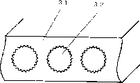
图4为实施例2的冷冻循环装置中使用的热交换器的传热管的要部放大结构图。与实施例1的不同之点在于,将放热器和蒸发器的制冷剂流路即扁平管31内形成的多个贯通小孔作为在内表面上设有许多小三角形槽的带内面槽小孔32。带内面槽小孔32的外径(与槽底部连接的假想直径)为1mm、槽深为0.1mm。并且,冷冻机油采用有极性油即聚醇酯油(POE油),将该油中水分量调整为100ppm以下。FIG. 4 is an enlarged structural view of a main part of a heat transfer tube of a heat exchanger used in the refrigeration cycle apparatus of Example 2. FIG. The difference from
这样,由于将热交换器的制冷剂流路即贯通小孔作为在其内表面上设有许多的小三角形槽的带内面槽小孔32,因此增大了制冷剂流路的传热面积,同时利用微小的槽所起的制冷剂的搅拌作用等,能极大地提高制冷剂的热传递率。In this way, since the refrigerant flow path of the heat exchanger, that is, the through hole is used as the small hole 32 with inner surface grooves with many small triangular grooves on its inner surface, the heat transfer area of the refrigerant flow path is increased, At the same time, the heat transfer rate of the refrigerant can be greatly improved by utilizing the stirring action of the refrigerant by the tiny grooves.
另外,本实施例中因采用有极性油即聚醇酯油(POE油),故从压缩机与CO2制冷剂一起在循环中吐出的冷冻机油被溶解于CO2制冷剂中。结果是在构成放热器和蒸发器的制冷剂流路的扁平管31的带内面槽小孔32的管内壁面上形成了起热阻作用的油膜,不会降低传热性能,可有效地利用具有CO2制冷剂的高的热传递率。In addition, in this embodiment, polyol ester oil (POE oil), which is a polar oil, is used, so the refrigerating machine oil discharged from the compressor in circulation together with the CO 2 refrigerant is dissolved in the CO 2 refrigerant. As a result, an oil film that acts as a thermal resistance is formed on the inner wall surface of the
又,由于在带内面槽小孔32的管内壁面上未形成油膜,且油滴不流动,因此不会导致压力损失增大。由此,管内热传递率非常高,可抑止因压力损失造成的性能下降,可作成小型且高性能的热交换器。Also, since no oil film is formed on the inner wall surface of the tube with the inner grooved small hole 32, and the oil droplets do not flow, the pressure loss does not increase. Thereby, the heat transfer rate in the tube is very high, performance degradation due to pressure loss can be suppressed, and a small and high-performance heat exchanger can be produced.
在以上的说明中对采用聚醇酯油(POE油)作为有极性油作了说明,但即使采用其它有极性油,也因对于CO2制冷剂的溶解度高而可获得同样的效果。In the above description, polyol ester oil (POE oil) was used as the polar oil, but even if other polar oil is used, the same effect can be obtained because of its high solubility to CO 2 refrigerant.
又,本实施例中,由于将冷冻机油中含有的水分量调整在100ppm以下,因此使用有极性油时加水分解不会使冷冻机油劣化,不会损害可靠性。Also, in this embodiment, since the water content in the refrigerating machine oil is adjusted to 100 ppm or less, hydrolysis does not degrade the refrigerating machine oil when polar oil is used, and reliability is not impaired.
(实施例3)(Example 3)
下面参照附图说明本发明实施例3中的冷冻循环装置。A refrigeration cycle apparatus in
图5为实施例3的冷冻循环装置中使用的热交换器的传热管要部放大结构图。与实施例2的不同之点在于,将放热器和蒸发器的制冷剂流路即扁平管41内形成的多个带内面槽小孔的槽的形状作成梯形的带梯形内面槽小孔42。带内面槽小孔42的外径(与槽底部连接的假想直径)为1mm、槽深为0.1mm。以及槽数与上述实施例2的三角形槽(图5中的虚线43)的场合一样,其槽的形状呈梯形。并且,冷冻机油采用有极性油即聚醇酯油(PVE油),将该油中水分量调整为100ppm以下。Fig. 5 is an enlarged structural view of a main part of a heat transfer tube of a heat exchanger used in the refrigeration cycle apparatus of the third embodiment. The difference from
这样,由于将热交换器的制冷剂流路即贯通小孔作为在其内表面上设有小的梯形槽的带内面槽小孔42,因此,与具有同一槽深、同一槽数的三角形的上述实施例2的传热管相比增大了制冷剂流路的传热面积,同时增大了制冷剂流路的浸湿边缘长度,减小了相当大的直径,再加上利用微小的槽所起的制冷剂的搅拌作用等,又由于增大了槽内的制冷剂的保持能力,在环状流的场合使液膜厚度均一化等,能极大地提高制冷剂的热传递率。另外,上述实施例2中可实现高热传递率,但因存在着该槽,有可能会发生促使油滴形成的不良现象,因本实施例3中是梯形,能进一步减少油膜形成。In this way, since the refrigerant flow path of the heat exchanger, that is, the through hole, is provided with a small trapezoidal groove on its inner surface, the small hole with inner surface groove 42, therefore, it is different from the triangular shape with the same groove depth and the same number of grooves. Compared with the heat transfer tube of the above-mentioned
另外,本实施例中,因采用有极性油即聚乙烯醚油(PVE油),故从压缩机与CO2制冷剂一起在循环中吐出的冷冻机油被溶解于CO2制冷剂中。结果是在构成放热器和蒸发器的制冷剂流路的扁平管41的带内面槽小孔42的管内壁面上形成了起热阻作用的油膜,不会降低传热性能,可有效地利用具有CO2制冷剂的高的热传递率。In addition, in this embodiment, polyvinyl ether oil (PVE oil), which is a polar oil, is used, so the refrigerating machine oil discharged from the compressor in circulation together with the CO 2 refrigerant is dissolved in the CO 2 refrigerant. As a result, an oil film that acts as a thermal resistance is formed on the inner wall surface of the flat tube 41 with the small hole 42 on the inner surface of the refrigerant flow path of the radiator and the evaporator, which can effectively utilize the heat transfer performance without reducing the heat transfer performance. High heat transfer rate with CO 2 refrigerant.
又,由于在带内面槽小孔42的管内壁面上未形成油膜,且油滴不流动,因此不会导致压力损失增大。由此,管内热传递率非常高,可抑止因压力损失造成的性能下降,可作成小型且高性能的热交换器。Also, since no oil film is formed on the inner wall surface of the tube with the small hole 42 having the inner surface groove, and the oil droplets do not flow, the pressure loss does not increase. Thereby, the heat transfer rate in the tube is very high, performance degradation due to pressure loss can be suppressed, and a small and high-performance heat exchanger can be produced.
在以上的说明中对使用聚乙烯醚油(PVE油)作为有极性油作了说明,但即使使用其它有极性油也因对于CO2制冷剂的溶解度高而可获得同样的效果。In the above description, polyvinyl ether oil (PVE oil) was used as the polar oil, but even if other polar oil is used, the same effect can be obtained due to its high solubility to CO 2 refrigerant.
又,本实施例中由于将冷冻机油中含有的水分量调整在100ppm以下,因此使用有极性油时通过加水分解不会使冷冻机油劣化,不会损害可靠性。Also, in this embodiment, since the water content in the refrigerating machine oil is adjusted to 100 ppm or less, the refrigerating machine oil is not degraded by hydrolysis when polar oil is used, and reliability is not impaired.
产业上的可利用性Industrial availability
从上述说明中可以看出,采用本发明,通过在扁平管上形成的多个贯通小孔作为对CO2制冷剂的热交换器的制冷剂流路,采用以有极性油为主体组成的冷冻机油,在贯通小孔的管内壁面上形成了起着热阻和流动阻力的油膜,由此,可抑止热交换器中的热传递率的下降以及压力损失的增大,可实现小型且使用高效率的CO2制冷剂的冷冻循环装置。As can be seen from the above description, the present invention uses a plurality of small through-holes formed on the flat tube as the refrigerant flow path of the heat exchanger for the CO 2 refrigerant, and uses polar oil as the main composition. The refrigerating machine oil forms an oil film on the inner wall surface of the tube passing through the small hole, which acts as thermal resistance and flow resistance, thereby suppressing a decrease in the heat transfer rate and an increase in pressure loss in the heat exchanger, and realizing a compact and usable High-efficiency CO 2 refrigerant refrigeration cycle device.
Claims (6)
Applications Claiming Priority (2)
| Application Number | Priority Date | Filing Date | Title |
|---|---|---|---|
| JP2001153508 | 2001-05-23 | ||
| JP153508/2001 | 2001-05-23 |
Publications (1)
| Publication Number | Publication Date |
|---|---|
| CN1526061A true CN1526061A (en) | 2004-09-01 |
Family
ID=18998013
Family Applications (1)
| Application Number | Title | Priority Date | Filing Date |
|---|---|---|---|
| CNA028100395A Withdrawn CN1526061A (en) | 2001-05-23 | 2002-05-21 | Refrigeration cycle device |
Country Status (6)
| Country | Link |
|---|---|
| US (1) | US20040206109A1 (en) |
| EP (1) | EP1389721A1 (en) |
| JP (1) | JPWO2002095302A1 (en) |
| KR (1) | KR20040036874A (en) |
| CN (1) | CN1526061A (en) |
| WO (1) | WO2002095302A1 (en) |
Cited By (2)
| Publication number | Priority date | Publication date | Assignee | Title |
|---|---|---|---|---|
| CN113853502A (en) * | 2019-05-31 | 2021-12-28 | 三菱电机株式会社 | Refrigeration cycle device and refrigerator |
| CN115398160A (en) * | 2020-01-31 | 2022-11-25 | 达克股份公司 | Refrigeration unit with dynamic air cooling and working element of said unit |
Families Citing this family (23)
| Publication number | Priority date | Publication date | Assignee | Title |
|---|---|---|---|---|
| JP4196774B2 (en) * | 2003-07-29 | 2008-12-17 | 株式会社デンソー | Internal heat exchanger |
| JP2008506885A (en) * | 2004-07-13 | 2008-03-06 | タイアックス エルエルシー | Refrigeration system and refrigeration method |
| JP2006090657A (en) * | 2004-09-24 | 2006-04-06 | Furukawa Electric Co Ltd:The | Heat exchanger tube for heat exchanger and manufacturing method thereof |
| DE112005003260T5 (en) * | 2004-12-24 | 2008-01-03 | Showa Denko K.K. | heat exchangers |
| WO2006101565A1 (en) * | 2005-03-18 | 2006-09-28 | Carrier Commercial Refrigeration, Inc. | Heat exchanger arrangement |
| DE102005016540A1 (en) * | 2005-04-08 | 2006-10-12 | Behr Gmbh & Co. Kg | Multichannel flat tube |
| FR2890435B1 (en) * | 2005-09-07 | 2007-09-28 | Commissariat Energie Atomique | HEAT EXCHANGER COMPRISING A SUPERCRITICAL CARBON DIOXIDE CIRCUIT |
| FR2895786B1 (en) * | 2006-01-04 | 2008-04-11 | Valeo Systemes Thermiques | RELAXATION MODULE FOR AIR CONDITIONING INSTALLATION WITH TWO EVAPORATORS |
| JP2008020166A (en) * | 2006-07-14 | 2008-01-31 | Kobelco & Materials Copper Tube Inc | Inner surface grooved heat-transfer tube for evaporator |
| US7631511B2 (en) * | 2006-08-08 | 2009-12-15 | Eid Al-Azmi | Portable air conditioning and water cooling apparatus |
| JP2008122059A (en) * | 2006-10-18 | 2008-05-29 | Daikin Ind Ltd | Heat exchanger and refrigeration equipment |
| JP2012073028A (en) * | 2006-10-18 | 2012-04-12 | Daikin Industries Ltd | Heat exchanger |
| JP5143461B2 (en) * | 2007-03-27 | 2013-02-13 | Jx日鉱日石エネルギー株式会社 | Refrigerating machine oil for carbon dioxide refrigerant and working fluid composition for refrigerator. |
| JP2010002099A (en) * | 2008-06-19 | 2010-01-07 | Mitsubishi Electric Corp | Refrigerating cycle device |
| ES2764787T3 (en) * | 2009-11-03 | 2020-06-04 | Carrier Corp | Pressure peak reduction for coolant systems incorporating a microchannel heat exchanger |
| CN103635771A (en) | 2011-06-27 | 2014-03-12 | 开利公司 | Micro-port shell and tube heat exchanger |
| WO2013132679A1 (en) * | 2012-03-07 | 2013-09-12 | 三菱電機株式会社 | Heat exchanger and refrigeration cycle device |
| US20150068707A1 (en) * | 2013-09-09 | 2015-03-12 | Nec Corporation | Electronic component cooling apparatus |
| JP5999081B2 (en) * | 2013-12-24 | 2016-09-28 | 株式会社豊田中央研究所 | Cooled element and selective deposition method |
| US10473226B2 (en) * | 2017-06-12 | 2019-11-12 | Hamilton Sundstrand Corporation | Heat exchanger valves |
| US11725889B1 (en) * | 2019-02-26 | 2023-08-15 | National Technology & Engineering Solutions Of Sandia, Llc | Refractory high entropy alloy compact heat exchanger |
| US11519670B2 (en) | 2020-02-11 | 2022-12-06 | Airborne ECS, LLC | Microtube heat exchanger devices, systems and methods |
| US12416453B1 (en) | 2021-07-22 | 2025-09-16 | Intergalactic Spaceworx, LLC | Heat exchange header with refrigerant distribution by capillary wicking porous insert |
Family Cites Families (6)
| Publication number | Priority date | Publication date | Assignee | Title |
|---|---|---|---|---|
| JP3573640B2 (en) * | 1998-03-04 | 2004-10-06 | 株式会社神戸製鋼所 | Boiling heat transfer tube |
| JP2000073951A (en) * | 1998-08-31 | 2000-03-07 | Mitsubishi Electric Corp | Refrigerant compressor and refrigeration cycle using the refrigerant compressor |
| JP2000193389A (en) * | 1998-12-28 | 2000-07-14 | Hitachi Ltd | Outdoor unit of air conditioner |
| JP2001133075A (en) * | 1999-11-09 | 2001-05-18 | Sanden Corp | Heat exchanger in refrigerating circuit |
| JP2001330388A (en) * | 2000-05-19 | 2001-11-30 | Matsushita Electric Ind Co Ltd | Heat exchanger unit |
| JP2002188872A (en) * | 2000-12-20 | 2002-07-05 | Matsushita Electric Ind Co Ltd | Refrigeration cycle device |
-
2002
- 2002-05-21 CN CNA028100395A patent/CN1526061A/en not_active Withdrawn
- 2002-05-21 WO PCT/JP2002/004904 patent/WO2002095302A1/en not_active Ceased
- 2002-05-21 JP JP2002591734A patent/JPWO2002095302A1/en active Pending
- 2002-05-21 EP EP02728095A patent/EP1389721A1/en not_active Withdrawn
- 2002-05-21 KR KR10-2003-7015148A patent/KR20040036874A/en not_active Abandoned
- 2002-05-21 US US10/476,040 patent/US20040206109A1/en not_active Abandoned
Cited By (2)
| Publication number | Priority date | Publication date | Assignee | Title |
|---|---|---|---|---|
| CN113853502A (en) * | 2019-05-31 | 2021-12-28 | 三菱电机株式会社 | Refrigeration cycle device and refrigerator |
| CN115398160A (en) * | 2020-01-31 | 2022-11-25 | 达克股份公司 | Refrigeration unit with dynamic air cooling and working element of said unit |
Also Published As
| Publication number | Publication date |
|---|---|
| WO2002095302A1 (en) | 2002-11-28 |
| KR20040036874A (en) | 2004-05-03 |
| US20040206109A1 (en) | 2004-10-21 |
| JPWO2002095302A1 (en) | 2004-09-09 |
| EP1389721A1 (en) | 2004-02-18 |
Similar Documents
| Publication | Publication Date | Title |
|---|---|---|
| CN1526061A (en) | Refrigeration cycle device | |
| CN1202392C (en) | Refrigeration cycle device | |
| CN1122794C (en) | Refrigerating and air conditioning device | |
| CN1214224C (en) | Regenerative refrigeration system with mixed refrigerants | |
| JP6065429B2 (en) | Air conditioner | |
| CN1166907C (en) | Air conditioner using combustible refrigerant | |
| CN1492986A (en) | Refrigeration cycle device | |
| WO2019124399A1 (en) | Compression machine | |
| CN1303385C (en) | Oil separator and cooling-cycle apparatus using the same | |
| CN1388887A (en) | Nonflammable mixed refrigerants (MR) for use with very low temperature throttle-cycle refrigeration systems | |
| CN1732365A (en) | Refrigeration system with bypass subcooling and component size de-optimization | |
| CN1685181A (en) | Very low temperature refrigeration system having a scroll compressor with liquid injection | |
| CN1723373A (en) | Air conditioner | |
| CN102713487A (en) | Heat transfer tube for heat exchanger, heat exchanger, refrigeration cycle device, and air conditioning device | |
| AU756502B2 (en) | Freezer | |
| JP2007278666A (en) | Dual refrigeration equipment | |
| JP2001343173A (en) | Refrigeration cycle device for CO2 refrigerant | |
| JP2008122059A (en) | Heat exchanger and refrigeration equipment | |
| US10365021B2 (en) | Cooling apparatus and compressor | |
| JP2008309443A (en) | Heat transfer tube connection structure | |
| CN1849485A (en) | Hot water takeout method by heat pump | |
| CN104567139A (en) | Refrigeration cycle device and air conditioning device | |
| CN2460895Y (en) | Refrigerating plant | |
| WO2020050022A1 (en) | Electric compressor, and refrigeration and air conditioning device using same | |
| JP2007315638A (en) | Refrigeration cycle equipment |
Legal Events
| Date | Code | Title | Description |
|---|---|---|---|
| C06 | Publication | ||
| PB01 | Publication | ||
| C10 | Entry into substantive examination | ||
| SE01 | Entry into force of request for substantive examination | ||
| C04 | Withdrawal of patent application after publication (patent law 2001) | ||
| WW01 | Invention patent application withdrawn after publication |