CN1526079A - Optical waveguide type diffraction grating element and manufacturing method thereof - Google Patents
Optical waveguide type diffraction grating element and manufacturing method thereof Download PDFInfo
- Publication number
- CN1526079A CN1526079A CNA028137426A CN02813742A CN1526079A CN 1526079 A CN1526079 A CN 1526079A CN A028137426 A CNA028137426 A CN A028137426A CN 02813742 A CN02813742 A CN 02813742A CN 1526079 A CN1526079 A CN 1526079A
- Authority
- CN
- China
- Prior art keywords
- refractive index
- optical waveguide
- diffraction grating
- grating element
- type diffraction
- Prior art date
- Legal status (The legal status is an assumption and is not a legal conclusion. Google has not performed a legal analysis and makes no representation as to the accuracy of the status listed.)
- Pending
Links
Images







Classifications
-
- G—PHYSICS
- G02—OPTICS
- G02B—OPTICAL ELEMENTS, SYSTEMS OR APPARATUS
- G02B6/00—Light guides; Structural details of arrangements comprising light guides and other optical elements, e.g. couplings
- G02B6/02—Optical fibres with cladding with or without a coating
- G02B6/02057—Optical fibres with cladding with or without a coating comprising gratings
- G02B6/02076—Refractive index modulation gratings, e.g. Bragg gratings
- G02B6/02123—Refractive index modulation gratings, e.g. Bragg gratings characterised by the method of manufacture of the grating
- G02B6/02133—Refractive index modulation gratings, e.g. Bragg gratings characterised by the method of manufacture of the grating using beam interference
- G02B6/02138—Refractive index modulation gratings, e.g. Bragg gratings characterised by the method of manufacture of the grating using beam interference based on illuminating a phase mask
-
- G—PHYSICS
- G02—OPTICS
- G02B—OPTICAL ELEMENTS, SYSTEMS OR APPARATUS
- G02B6/00—Light guides; Structural details of arrangements comprising light guides and other optical elements, e.g. couplings
- G02B6/02—Optical fibres with cladding with or without a coating
-
- G—PHYSICS
- G02—OPTICS
- G02B—OPTICAL ELEMENTS, SYSTEMS OR APPARATUS
- G02B6/00—Light guides; Structural details of arrangements comprising light guides and other optical elements, e.g. couplings
- G02B6/02—Optical fibres with cladding with or without a coating
- G02B6/02057—Optical fibres with cladding with or without a coating comprising gratings
- G02B6/02076—Refractive index modulation gratings, e.g. Bragg gratings
- G02B6/0208—Refractive index modulation gratings, e.g. Bragg gratings characterised by their structure, wavelength response
- G02B6/02085—Refractive index modulation gratings, e.g. Bragg gratings characterised by their structure, wavelength response characterised by the grating profile, e.g. chirped, apodised, tilted, helical
Landscapes
- Physics & Mathematics (AREA)
- General Physics & Mathematics (AREA)
- Optics & Photonics (AREA)
- Engineering & Computer Science (AREA)
- Manufacturing & Machinery (AREA)
- Optical Integrated Circuits (AREA)
- Diffracting Gratings Or Hologram Optical Elements (AREA)
Abstract
Description
技术领域technical field
本发明涉及沿光波导的长度方向形成了折射率调制部的光波导型衍射光栅元件及其制造方法。The present invention relates to an optical waveguide type diffraction grating element in which a refractive index modulation portion is formed along the longitudinal direction of an optical waveguide, and a method for manufacturing the same.
背景技术Background technique
光波导型衍射光栅元件是沿光波导(例如光纤)的长度方向的规定范围形成了折射率调制部的元件。通常的光波导型衍射光栅元件中,与折射率等位面(折射率调制部中的折射率相等的面)垂直的直线与光波导的光轴平行。在此情况下,折射率调制周期为Λ,如果光波导的折射率调制部的平均有效折射率为nave,则该光波导型衍射光栅元件有选择地反射满足用λ=2naveΛ式表示的布拉格条件式的反射波长为λ的光,使其他波长的光透过。在该折射率调制部中反射的反射波长为λ的光沿着与入射时相反的方向在光波导中传播。The optical waveguide type diffraction grating element is an element in which a refractive index modulation portion is formed along a predetermined range in the longitudinal direction of an optical waveguide (for example, an optical fiber). In a general optical waveguide type diffraction grating element, a straight line perpendicular to a refractive index equipotential plane (a plane with an equal refractive index in the refractive index modulating portion) is parallel to the optical axis of the optical waveguide. In this case, the refractive index modulation period is Λ, and if the average effective refractive index of the refractive index modulation part of the optical waveguide is n ave , then the selective reflection of the optical waveguide type diffraction grating element satisfies the expression of λ=2n ave Λ The Bragg conditional formula reflects light of wavelength λ and transmits light of other wavelengths. The light having a reflection wavelength λ reflected by the refractive index modulator propagates through the optical waveguide in a direction opposite to that of the incident light.
与此不同,已知一种垂直于折射率等位面的直线与光波导的光轴不平行的光波导型衍射光栅元件(以下称“倾斜型衍射光栅元件”)(参照例如文献“M.J.Holmes等人,“Ultra Narrow-Band Optical Fibre Sidetap Filters”,ECOC’98,第137-138页(1998)”)。图1A及图1B是现有的倾斜型衍射光栅元件的说明图。图1A是用包含倾斜型衍射光栅元件的光轴的面切断时的剖面图,图1B是用垂直于光轴的面切断时的剖面图。该图所示的现有的倾斜型衍射光栅元件9是,在具有高折射率的纤芯区域91及低折射率的包层区域92的光纤90中,在沿着该纤芯区域91的长度方向的规定范围内形成折射率调制部93。而且,垂直于折射率调制部93的折射率等位面L直线A不与光纤90的光轴(图中的x轴)平行,直线A和光轴构成的角θ不为0。在此情况下,沿直线A的折射率调制周期为Λ,如果折射率调制部93的平均有效折射率为nave,则该倾斜型衍射光栅元件9有选择地反射满足用λ=2naveΛ/sinθ式表示的布雷格条件式的反射波长为λ的光,使其他波长的光透过。在该折射率调制部93中反射的反射波长为λ的光不在光纤90中传播,而发射到光纤90的外部。即,该倾斜型衍射光栅元件作为低反射损失的光纤起作用。因此,该倾斜型衍射光栅元件9适合作为例如使光纤放大器的增益均衡的增益均衡器使用。In contrast to this, there is known an optical waveguide type diffraction grating element in which a straight line perpendicular to the refractive index equipotential plane is not parallel to the optical axis of the optical waveguide (hereinafter referred to as "slant type diffraction grating element") (refer to, for example, the literature "MJ Holmes et al. Al, "Ultra Narrow-Band Optical Fiber Sidetap Filters", ECOC'98, pp. 137-138 (1998)"). 1A and 1B are explanatory diagrams of a conventional oblique diffraction grating element. FIG. 1A is a cross-sectional view taken along a plane including the optical axis of the inclined diffraction grating element, and FIG. 1B is a cross-sectional view taken along a plane perpendicular to the optical axis. In the conventional tilted
可是,现有的倾斜型衍射光栅元件9的损失特性有偏振波相关性。即,在具有平行于由直线A和光轴构成的偏移角面M(图1A及图1B中的xy平面)的偏振波面的偏振波模式、以及具有垂直于偏移角面M的偏振波面的偏振波模式中,损失特性不同。However, the loss characteristic of the conventional inclined
因此,为了降低这样的偏振波相关损失,例如可以考虑将现有的倾斜型衍射光栅元件绕光轴扭转,使偏移角面沿长度方向旋转,使各个偏移角面不同。如果这样做,则长度方向的某位置及另一位置各自的偏振波相关损失互相抵消,能降低偏振波相关损失。Therefore, in order to reduce such polarization-dependent loss, it is conceivable, for example, to twist the conventional tilted diffraction grating element around the optical axis, rotate the offset angle planes in the longitudinal direction, and make each offset angle plane different. By doing so, the polarization-dependent losses at one position and another position in the longitudinal direction cancel each other out, and the polarization-dependent loss can be reduced.
可是,在扭转倾斜型衍射光栅元件的情况下,由于光纤是由玻璃构成的,很脆弱,所以为了降低偏振波相关损失,有必要使折射率调制部增长。另外,在连接多个折射率调制部的情况下,由于熔融连接而需要备有长度富余部,所以折射率调制部总体增长了。现有的倾斜型衍射光栅元件无论如何也不能用较短的尺寸降低偏振波相关损失。However, in the case of the twisted-tilt type diffraction grating element, since the optical fiber is made of glass and is fragile, it is necessary to increase the length of the refractive index modulation section in order to reduce the polarization-dependent loss. In addition, in the case of connecting a plurality of refractive index modulation parts, it is necessary to provide a length margin part due to the fusion connection, so that the overall refractive index modulation part increases. Existing tilted diffraction grating elements cannot reduce polarization-dependent loss with a shorter size anyway.
本发明就是为了解决上述问题而完成的,其目的在于提供一种光波导型衍射光栅元件(倾斜型衍射光栅元件)及其制造方法。The present invention was made in order to solve the above problems, and an object of the present invention is to provide an optical waveguide type diffraction grating element (slant type diffraction grating element) and a manufacturing method thereof.
发明内容Contents of the invention
本发明的光波导型衍射光栅元件的特征在于:(1)沿光波导的长度方向形成N(N是2以上的整数)个折射率调制部,(2)N个折射率调制部各自的垂直于折射率等位面的直线不平行于光波导的光轴,(3)N个折射率调制部各自的垂直于折射率等位面的直线和光波导的光轴构成的偏移角面互相不一致,(4)N个折射率调制部中的任意两个折射率调制部各自的形成区域至少一部分互相重叠。The optical waveguide type diffraction grating element of the present invention is characterized in that: (1) N (N is an integer greater than or equal to 2) refractive index modulation parts are formed along the longitudinal direction of the optical waveguide; The straight line on the equipotential plane of refractive index is not parallel to the optical axis of the optical waveguide, and (3) the offset angle planes formed by the straight lines perpendicular to the equipotential plane of refractive index and the optical axis of the optical waveguide of the N refractive index modulation parts are inconsistent with each other , (4) Formation regions of any two of the N refractive index modulation portions overlap each other at least in part.
本发明的光波导型衍射光栅元件的制造方法的特征在于:(1)沿光波导的长度方向依次形成N(N是2以上的整数)个折射率调制部,且使垂直于折射率等位面的直线不平行于光波导的光轴,同时(2)形成第n(n是2以上N以下的整数)个折射率调制部时,垂直于折射率等位面的直线和光波导的光轴构成的偏移角面与已经形成的第一至第(n-1)个折射率调制部各自的偏移角面中的任何一个都不一致,(3)N个折射率调制部中的任意两个折射率调制部各自的形成区域至少一部分互相重叠地制造光波导型衍射光栅元件。The method for manufacturing an optical waveguide type diffraction grating element of the present invention is characterized in that: (1) N (N is an integer greater than or equal to 2) refractive index modulators are sequentially formed along the longitudinal direction of the optical waveguide, and the refractive index modulation parts perpendicular to the refractive index equipotential The straight line on the surface is not parallel to the optical axis of the optical waveguide, and (2) when the nth (n is an integer of 2 to N) refractive index modulator is formed, the straight line perpendicular to the refractive index equipotential plane and the optical axis of the optical waveguide The formed offset angle surface is not consistent with any of the offset angle surfaces of the first to (n-1)th refractive index modulation parts that have been formed, and (3) any two of the N refractive index modulation parts An optical waveguide type diffraction grating element is manufactured in such a manner that at least a part of the formation regions of the respective refractive index modulating portions overlap each other.
本发明的光波导型衍射光栅元件、以及采用本发明的光波导型衍射光栅元件的制造方法制造的光波导型衍射光栅元件形成N个折射率调制部,垂直于各折射率调制部的折射率等位面的直线与光波导的光轴不平行,各折射率调制部的偏移角面互相不一致,任意两个折射率调制部各自的形成区域至少一部分互相重叠。由于这样构成,所以光波导型衍射光栅元件的尺寸短,能降低偏振波相关损失。The optical waveguide type diffraction grating element of the present invention and the optical waveguide type diffraction grating element manufactured by the method of manufacturing the optical waveguide type diffraction grating element of the present invention form N refractive index modulation parts, and the refractive index of each refractive index modulation part The straight line of the equipotential surface is not parallel to the optical axis of the optical waveguide, the offset angle planes of the respective refractive index modulation parts are not coincident with each other, and the formation regions of any two refractive index modulation parts overlap with each other at least in part. With such a configuration, the size of the optical waveguide type diffraction grating element is short, and the polarization-dependent loss can be reduced.
另外,本发明的光波导型衍射光栅元件的特征在于:N个折射率调制部各自的偏移角面绕光波导的光轴各偏移180度/N。本发明的光波导型衍射光栅元件的制造方法的特征在于:使N个折射率调制部各自的偏移角面绕光波导的光轴各偏移180度/N,制造光波导型衍射光栅元件。在此情况下,光波导型衍射光栅元件能有效地降低偏振波相关损失。In addition, the optical waveguide type diffraction grating element of the present invention is characterized in that the offset angle planes of the N refractive index modulators are each offset by 180 degrees/N around the optical axis of the optical waveguide. The method for manufacturing an optical waveguide type diffraction grating element according to the present invention is characterized in that the offset angle planes of the N refractive index modulation parts are each shifted by 180 degrees/N around the optical axis of the optical waveguide to manufacture an optical waveguide type diffraction grating element . In this case, the optical waveguide type diffraction grating element can effectively reduce the polarization dependent loss.
另外,本发明的光波导型衍射光栅元件的特征在于:N个折射率调制部各自的偏移角面绕光波导的光轴各偏移360度/N。本发明的光波导型衍射光栅元件的制造方法的特征在于:使N个折射率调制部各自的偏移角面绕光波导的光轴各偏移360度/N,制造光波导型衍射光栅元件。与上述的各偏移180度/N的情况相比,在这样各偏移360度/N的情况下,光波导型衍射光栅元件能更有效地降低偏振波相关损失。另外,N可以是奇数,也可以是偶数。如果N是偶数,则由于偏移角面相差180度的一对折射率调制部分别具有的非对称性引起的双折射性互相抵消,因此光波导型衍射光栅元件更能有效地降低偏振波相关损失。In addition, the optical waveguide type diffraction grating element of the present invention is characterized in that the offset angle planes of the N refractive index modulators are each offset by 360 degrees/N around the optical axis of the optical waveguide. The method for manufacturing an optical waveguide type diffraction grating element according to the present invention is characterized in that the offset angle planes of the N refractive index modulation parts are each shifted by 360 degrees/N around the optical axis of the optical waveguide to manufacture an optical waveguide type diffraction grating element . Compared with the above-mentioned case of each shift of 180 degrees/N, in the case of each shift of 360 degrees/N, the optical waveguide type diffraction grating element can more effectively reduce the polarization-dependent loss. In addition, N may be an odd number or an even number. If N is an even number, the birefringence caused by the asymmetry of the pair of refractive index modulation parts whose offset angle planes differ by 180 degrees cancels each other out, so the optical waveguide type diffraction grating element can more effectively reduce polarization correlation. loss.
另外,在本发明的光波导型衍射光栅元件中,特征在于:N个折射率调制部各自的垂直于折射率等位面的直线和光波导的光轴构成的角度彼此相同,沿光波导的长度方向的形成区域的长度彼此相同,折射率调制周期彼此相同,折射率调制振幅彼此相同。本发明的光波导型衍射光栅元件的制造方法的特征在于:在分别形成N个折射率调制部时,使垂直于折射率等位面的直线和光波导的光轴构成的角度彼此相同,使沿光波导的长度方向的形成区域的长度彼此相同,使折射率调制周期彼此相同,使折射率调制振幅彼此相同。在此情况下,光波导型衍射光栅元件也能有效地降低偏振波相关损失。In addition, in the optical waveguide type diffraction grating element of the present invention, it is characterized in that the angles formed by the straight lines perpendicular to the equipotential plane of the refractive index and the optical axis of the optical waveguide of each of the N refractive index modulation parts are the same as each other, and the length of the optical waveguide The lengths of the forming regions of the directions are the same as each other, the periods of the refractive index modulations are the same as each other, and the amplitudes of the refractive index modulations are the same as each other. The method for manufacturing an optical waveguide type diffraction grating element according to the present invention is characterized in that when forming N refractive index modulating portions, the angles formed by a straight line perpendicular to the equipotential plane of the refractive index and the optical axis of the optical waveguide are made the same, and The lengths of the formation regions in the longitudinal direction of the optical waveguides are the same, the periods of the refractive index modulations are made the same, and the amplitudes of the refractive index modulations are made the same. In this case, the optical waveguide type diffraction grating element is also effective in reducing polarization-dependent loss.
另外,在本发明的光波导型衍射光栅元件的特征在于:透射损失最大的波长中,偏振波相关损失为透射损失最大值的1/10以下。在此情况下,光波导型衍射光栅元件在光通信领域中作为要求偏振波相关损失小的光学装置(或其一部分)很适用。In addition, the optical waveguide type diffraction grating element of the present invention is characterized in that the polarization-dependent loss is 1/10 or less of the maximum value of the transmission loss at the wavelength at which the transmission loss is maximum. In this case, the optical waveguide type diffraction grating element is suitable as an optical device (or a part thereof) in the field of optical communication requiring a small polarization-dependent loss.
另外,本发明的光波导型衍射光栅元件的制造方法的特征在于:一边监视透射损失,一边分别形成N个折射率调制部。或者,特征在于:一边监视偏振波相关损失,一边分别形成N个折射率调制部。在此情况下,所制造的光波导型衍射光栅元件能有效地降低偏振波相关损失。In addition, the method of manufacturing an optical waveguide type diffraction grating element according to the present invention is characterized in that N refractive index modulation portions are each formed while monitoring transmission loss. Alternatively, it is characterized in that N refractive index modulators are respectively formed while monitoring polarization-dependent loss. In this case, the manufactured optical waveguide type diffraction grating element can effectively reduce the polarization dependent loss.
附图说明Description of drawings
图1A及图1B是现有的倾斜型衍射光栅元件的说明图。1A and 1B are explanatory diagrams of a conventional oblique diffraction grating element.
图2是本实施形态的光波导型衍射光栅元件(倾斜型衍射光栅元件)的说明图。FIG. 2 is an explanatory diagram of an optical waveguide type diffraction grating element (slant type diffraction grating element) according to this embodiment.
图3是用来说明本实施形态的光波导型衍射光栅元件的制造方法的斜视图。Fig. 3 is a perspective view illustrating a method of manufacturing the optical waveguide type diffraction grating element of the present embodiment.
图4A、图4B、图4C及图4D分别是用来说明本实施形态的光波导型衍射光栅元件的制造方法的剖面图。4A, 4B, 4C, and 4D are cross-sectional views for explaining a method of manufacturing the optical waveguide type diffraction grating element of this embodiment, respectively.
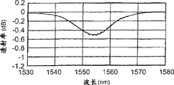
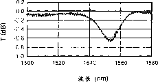
图5A及图5B是表示本实施形态的光波导型衍射光栅元件(倾斜型衍射光栅元件)的透射特性的图,图5A是表示第一个折射率调制部形成结束时刻的透射特性的图,图5B是表示第二个折射率调制部形成结束时刻的透射特性的图。5A and FIG. 5B are diagrams showing the transmission characteristics of the optical waveguide type diffraction grating element (slope type diffraction grating element) according to the present embodiment, and FIG. 5A is a diagram showing the transmission characteristics at the time when the formation of the first refractive index modulating portion is completed, FIG. 5B is a graph showing transmission characteristics at the time when formation of the second refractive index modulating portion is completed.
图6A及图6B分别是表示本实施形态的光波导型衍射光栅元件(倾斜型衍射光栅元件)的透射特性及偏振波相关损失特性的图。6A and 6B are graphs showing the transmission characteristics and polarization-dependent loss characteristics of the optical waveguide type diffraction grating element (slant type diffraction grating element) of the present embodiment, respectively.
图7A及图7B分别是表示比较例的光波导型衍射光栅元件(倾斜型衍射光栅元件)的透射特性及偏振波相关损失特性的图。7A and 7B are graphs showing the transmission characteristics and polarization-dependent loss characteristics of an optical waveguide type diffraction grating element (slant type diffraction grating element) of a comparative example, respectively.
图8是另一实施形态的光波导型衍射光栅元件(倾斜型衍射光栅元件)的说明图。Fig. 8 is an explanatory diagram of an optical waveguide type diffraction grating element (slant type diffraction grating element) according to another embodiment.
图9A及图9B分别是表示只从一个方向照射折射率变化诱导光,形成了一个折射率调制部的倾斜型衍射光栅元件的透射率T及偏振波相关损失PDL各自的波长相关性的曲线图。9A and 9B are graphs showing the respective wavelength dependencies of the transmittance T and polarization-dependent loss PDL of an inclined diffraction grating element in which one refractive index modulation portion is formed by irradiating refractive index change inducing light from only one direction. .
图10A及图10B分别是表示从相差90度的两个方向照射折射率变化诱导光,形成了两个折射率调制部的倾斜型衍射光栅元件1的透射率T及偏振波相关损失PDL各自的波长相关性的曲线图。10A and 10B respectively show the transmittance T and the polarization dependent loss PDL of the inclined
图11A及图11B分别是表示从相差90度的4个方向照射折射率变化诱导光,形成了4个折射率调制部的倾斜型衍射光栅元件2的透射率T及偏振波相关损失PDL各自的波长相关性的曲线图。11A and 11B respectively show the transmittance T and polarization-dependent loss PDL of the inclined diffraction grating element 2 formed with four refractive index modulation parts irradiated with refractive index change-inducing light from four directions with a difference of 90 degrees. Graph of wavelength dependence.
具体实施方式Detailed ways
以下,参照附图详细地说明本发明的实施形态。另外,在附图的说明中对同一要素赋予同一标记,省略重复的说明。Hereinafter, embodiments of the present invention will be described in detail with reference to the drawings. In addition, in the description of the drawings, the same reference numerals are assigned to the same elements, and overlapping descriptions are omitted.
图2是本实施形态的光波导型衍射光栅元件(倾斜型衍射光栅元件)1的说明图。在该图中,示出了用包含光轴的面切断时的剖面图、以及用垂直于光轴的面切断时的剖面图。该图所示的本实施形态的倾斜型衍射光栅元件1沿着作为光波导的光纤10的长度方向,形成N(N是2以上的整数)个折射率调制部131~13N。光纤10是以石英玻璃为基础的纤维,包括添加了GeO2的纤芯区域11、以及包围该纤芯区域11的包层区域12。FIG. 2 is an explanatory diagram of an optical waveguide type diffraction grating element (slant type diffraction grating element) 1 according to this embodiment. In this figure, a cross-sectional view taken along a plane including the optical axis and a cross-sectional view taken along a plane perpendicular to the optical axis are shown. The inclined diffraction
关于各折射率调制部13n(n是1以上N以下的任意的整数),将折射率相等的折射率等位面表示为Ln,将垂直于折射率等位面Ln、将与光纤10的光轴(x轴)相交的直线表示为An,将直线An和光轴构成的角表示为θn,将直线An和光轴构成的偏移角面表示为Mn。As for each refractive index modulator 13 n (n is an arbitrary integer ranging from 1 to N), a refractive index equipotential plane having the same refractive index is denoted as L n , and a refractive index equipotential plane perpendicular to the refractive index equipotential plane L n and an optical fiber The straight line where the optical axis (x-axis) of 10 intersects is denoted by A n , the angle formed by the straight line A n and the optical axis is denoted by θ n , and the offset angle surface formed by the straight line A n and the optical axis is denoted by M n .
对于各折射率调制部13n,直线An和光轴不平行,直线An和光轴构成的角θn不为0。即,各折射率调制部13n沿着相对于光轴以角度θn倾斜的直线,在纤芯区域11中形成了周期为Λn的折射率调制部。另外,各折射率调制部13n的偏移角面Mn互相不一致。即,取N个折射率调制部131~13N中的任意两个折射率调制部13n1、13n2时,偏移角面Mn1和偏移角面Mn2不一致。For each refractive index modulation portion 13 n , the straight line A n is not parallel to the optical axis, and the angle θ n formed by the straight line A n and the optical axis is not zero. That is, each refractive index modulator 13 n forms a refractive index modulator with a period of Λ n in the core region 11 along a straight line inclined at an angle θ n with respect to the optical axis. In addition, the off-angle planes M n of the respective refractive index modulators 13 n do not coincide with each other. That is, when any two refractive index modulation portions 13 n1 and 13 n2 are taken among the N refractive index modulation portions 13 1 to 13 N , the offset angle surface M n1 and the offset angle surface M n2 do not coincide.
N个折射率调制部131~13N中的任意两个折射率调制部13n1、13n2各自的形成区域至少一部分互相重叠。图中,例如折射率调制部131的形成区域与折射率调制部132的形成区域一部分重叠,还与折射率调制部133的形成区域一部分重叠。另外,N个折射率调制部131~13N各自的形成区域也可以全部一致。The respective formation regions of any two of the N refractive index modulation portions 13 1 to 13 N overlap each other at least in part. In the figure, for example, the formation region of the refractive index modulation portion 131 partially overlaps the formation region of the refractive index modulation portion 132 and also partially overlaps the formation region of the refractive index modulation portion 133 . In addition, the formation regions of the N refractive index modulators 13 1 to 13 N may all coincide with each other.
这样,本实施形态的倾斜型衍射光栅元件1形成N个折射率调制部131~13N,各折射率调制部13n的角度θn不为0,各折射率调制部13n的偏移角面Mn互相不一致,任意两个折射率调制部13n1、13n2各自的形成区域至少一部分互相重叠。这样构成的倾斜型衍射光栅元件1的尺寸短,能降低与偏振波相关的损失。In this way, the inclined diffraction
另外,N个折射率调制部131~13N各自的偏移角面M1~MN正好绕光纤10的光轴各偏移180度/N。例如,如果N=2,则偏移角面M1和偏移角面M2相正交。另外,例如,如果N=3,则偏移角面M1~M3绕光纤10的光轴各偏移60度。由于这样配置偏移角面M1~MN,所以倾斜型衍射光栅元件1能有效地降低偏振波相关损失。In addition, the offset angle surfaces M 1 -M N of each of the N refractive index modulators 13 1 -13 N are respectively offset by exactly 180 degrees/N around the optical axis of the optical fiber 10 . For example, if N=2, the offset angle surface M 1 and the offset angle surface M 2 are orthogonal. In addition, for example, if N=3, the offset angle surfaces M 1 -M 3 are each offset by 60 degrees around the optical axis of the optical fiber 10 . By arranging the offset angle surfaces M 1 to M N in this way, the oblique diffraction
另外,优选地,N个折射率调制部131~13N的各自的直线An和光轴构成的角度θn彼此相同,沿光纤10的长度方向的形成区域的长度彼此相同,折射率调制周期彼此相同,折射率调制振幅彼此相同。通过这样地形成各折射率调制部13n,倾斜型衍射光栅元件1可以有效地降低偏振波相关损失。In addition, preferably, the angles θ n formed by the straight lines A n of the N refractive index modulation parts 13 1 to 13 N and the optical axis are the same as each other, the lengths of the formation regions along the length direction of the optical fiber 10 are the same as each other, and the refractive index modulation period are identical to each other, and the refractive index modulation amplitudes are identical to each other. By forming each refractive index modulating portion 13 n in this way, the sloped diffraction
而且,本实施形态的倾斜型衍射光栅元件1在透射损失为最大的波长中,偏振波相关损失优选为透射损失最大值的1/10以下。这样的倾斜型衍射光栅元件1在光通信领域中作为要求偏振波相关损失小的光学装置(或其一部分)很适用,例如作为使光纤放大器的增益均衡的增益均衡器很适用。In addition, in the inclined diffraction
其次,说明本实施形态的光波导型衍射光栅元件(倾斜型衍射光栅元件)1的制造方法。图3及图4A至图4D是说明本实施形态的光波导型衍射光栅元件的制造方法用的图。图3是斜视图,图4A至图4D是用垂直于光轴的面切断时的剖面图。Next, a method of manufacturing the optical waveguide type diffraction grating element (slant type diffraction grating element) 1 of this embodiment will be described. 3 and FIGS. 4A to 4D are diagrams for explaining a method of manufacturing the optical waveguide type diffraction grating element of the present embodiment. 3 is a perspective view, and FIGS. 4A to 4D are cross-sectional views cut along a plane perpendicular to the optical axis.
首先,准备光纤10、相位光栅掩模20及光源30。如上所述,光纤10是以石英玻璃为基础的纤维,包括添加了GeO2的纤芯区域11、以及包围该纤芯区域11的包层区域12。相位光栅掩模20是在石英玻璃平板的一个面上形成了由周期为2Λ的槽状凹凸构成的相位光栅的掩模。光源30是输出引起光纤10的纤芯区域11的折射率变化的波长的光(以下称“折射率变化诱导光”)的光源,例如,采用将波长为248nm的激光作为折射率变化诱导光输出的KrF受激准分子激光光源。First, the optical fiber 10, the phase grating mask 20, and the light source 30 are prepared. As described above, the optical fiber 10 is a silica glass-based fiber, and includes a core region 11 doped with GeO 2 and a cladding region 12 surrounding the core region 11 . The phase grating mask 20 is a mask in which a phase grating composed of groove-shaped concavities and convexities with a period of 2Λ is formed on one surface of a quartz glass plate. The light source 30 is a light source that outputs light of a wavelength that causes a change in the refractive index of the core region 11 of the optical fiber 10 (hereinafter referred to as "refractive index change inducing light"). KrF excimer laser light source.
然后,如图3所示,相位光栅掩模20被配置在光纤10的侧面,且使形成了相位光栅的面与光纤10相对。另外,这时,相位光栅掩模20上的相位光栅的槽方向相对于垂直于光纤10的光轴的面,倾斜角度为θ1。在两者这样配置的状态下,从光源30输出的折射率变化诱导光UV垂直地照射在相位光栅掩模20上。伴随该折射率变化诱导光UV的照射,由于相位光栅掩模20的衍射作用,产生+1次衍射光和-1次衍射光,这些+1次衍射光和-1次衍射光互相干涉,生成周期为Λ的干涉条纹。在光纤10的添加了GeO2的纤芯区域11中,折射率对应于干各涉条纹位置上的折射率变化诱导光的能量的大小而升降,因此形成折射率调制部131。该折射率调制部131在垂直于折射率等位面L1、与光纤10的光轴相交的直线为A1时,该直线A1和光轴构成的角度为θ1,直线A1和光轴构成的偏移角面M1平行于相位光栅掩模20的面(参照图3及图4A)。Then, as shown in FIG. 3 , the phase grating mask 20 is arranged on the side surface of the optical fiber 10 so that the surface on which the phase grating is formed faces the optical fiber 10 . In addition, at this time, the groove direction of the phase grating on the phase grating mask 20 is inclined by an angle θ 1 with respect to the plane perpendicular to the optical axis of the optical fiber 10 . In the state where both are thus arranged, the refractive index change inducing light UV output from the light source 30 is irradiated vertically on the phase grating mask 20 . Accompanied by the irradiation of the refractive index change-inducing light UV, due to the diffraction effect of the phase grating mask 20, +1-order diffracted light and -1-order diffracted light are generated, and these +1-order diffracted light and -1-order diffracted light interfere with each other to generate Interference fringes with period Λ. In the GeO 2 -doped core region 11 of the optical fiber 10 , the refractive index rises and falls according to the energy of the refractive index change-induced light at the positions of the interference fringes, thereby forming the refractive index modulation portion 13 1 . In the refractive index modulator 131 , when the straight line perpendicular to the refractive index equipotential plane L 1 and intersecting the optical axis of the optical fiber 10 is A 1 , the angle formed by the straight line A 1 and the optical axis is θ 1 , and the straight line A 1 and the optical axis The offset angle surface M1 is formed parallel to the surface of the phase grating mask 20 (see FIG. 3 and FIG. 4A ).
这样,如图4A所示的配置状态下,使折射率变化诱导光UV照射一定时间,形成第一折射率调制部131。形成后,使折射率变化诱导光UV的照射中断,在此期间使光纤10绕光轴旋转一定角度,变成图4B所示的配置状态。然后,在图4B所示的配置状态下,使折射率变化诱导光UV照射一定时间,形成第二折射率调制部132。这样形成的第二折射率调制部132在垂直于折射率等位面L2、与光纤10的光轴相交的直线为A2时,该直线A2和光轴构成的角度为θ2,直线A2和光轴构成的偏移角面M2平行于相位光栅掩模20的面。第二折射率调制部132的偏移角面M2与已经形成的第一折射率调制部131的偏移角面M1不一致。In this way, in the arrangement state shown in FIG. 4A , the first refractive index modulation portion 13 1 is formed by irradiating the refractive index change inducing light UV for a certain period of time. After the formation, the irradiation of the refractive index change inducing light UV is interrupted, and the optical fiber 10 is rotated by a certain angle around the optical axis during this period, and the arrangement state shown in FIG. 4B is obtained. Then, in the arrangement state shown in FIG. 4B , the second refractive index modulation portion 13 2 is formed by irradiating the refractive index change inducing light UV for a certain period of time. In the second refractive index modulator 132 thus formed, when a straight line perpendicular to the equipotential plane of refraction L 2 and intersecting the optical axis of the optical fiber 10 is A 2 , the angle formed by the straight line A 2 and the optical axis is θ 2 , and the straight line The offset angle surface M 2 formed by A 2 and the optical axis is parallel to the surface of the phase grating mask 20 . The off-angle surface M 2 of the second refractive index modulation portion 13 2 is not consistent with the off-angle surface M 1 of the already formed first refractive index modulation portion 13 1 .
另外,形成了第二折射率调制部132后,使折射率变化诱导光UV的照射中断,在此期间使光纤10绕光轴旋转一定角度,变成图4C所示的配置状态。然后,在图4C所示的配置状态下,使折射率变化诱导光UV照射一定时间,形成第三折射率调制部133。这样形成的第三折射率调制部133在垂直于折射率等位面L3、与光纤10的光轴相交的直线为A3时,该直线A3和光轴构成的角度为θ3,直线A3和光轴构成的偏移角面M3平行于相位光栅掩模20的面。第三折射率调制部133的偏移角面M3与已经形成的第一折射率调制部131的偏移角面M1不一致,另外,与已经形成的第二折射率调制部132的偏移角面M2也不一致。In addition, after the formation of the second refractive index modulator 132 , the irradiation of the refractive index change inducing light UV is interrupted, and the optical fiber 10 is rotated by a certain angle around the optical axis during this period, and the arrangement state shown in FIG. 4C is obtained. Then, in the arrangement state shown in FIG. 4C , the third refractive index modulation portion 13 3 is formed by irradiating the refractive index change inducing light UV for a certain period of time. In the third refractive index modulator 133 formed in this way, when the straight line perpendicular to the equipotential plane L 3 of the refractive index and intersecting the optical axis of the optical fiber 10 is A 3 , the angle formed by the straight line A 3 and the optical axis is θ 3 , and the straight line The offset angle surface M 3 formed by A 3 and the optical axis is parallel to the surface of the phase grating mask 20 . The off-angle surface M3 of the third refractive index modulation part 133 is not consistent with the off-angle surface M1 of the already formed first refractive index modulation part 131 , and is different from the off angle surface M1 of the already formed second refractive index modulation part 132. The offset angle surface M2 is also inconsistent.
以后也一样,依次形成第四至第N折射率调制部134~13N。形成第N折射率调制部13N时,在图4D所示的配置状态下,使折射率变化诱导光UV照射一定时间,形成第N折射率调制部13N。这样形成的第N折射率调制部13N在垂直于折射率等位面LN、与光纤10的光轴相交的直线为AN时,该直线AN和光轴构成的角度为θN,直线AN和光轴构成的偏移角面MN平行于相位光栅掩模20的面。第N折射率调制部13N的偏移角面MN与已经形成的第一至第(N-1)折射率调制部131~13N-1的偏移角面M1~MN-1中的任何一个都不一致。In the same manner thereafter, the fourth to Nth refractive index modulation portions 13 4 to 13 N are sequentially formed. When forming the Nth refractive index modulation part 13N , the Nth refractive index modulation part 13N is formed by irradiating the refractive index change inducing light UV for a certain period of time in the arrangement state shown in FIG. 4D. In the Nth refractive index modulator 13N formed in this way, when a straight line perpendicular to the refractive index equipotential plane L N and intersecting the optical axis of the optical fiber 10 is A N , the angle formed by the straight line A N and the optical axis is θ N , and the straight line An offset angle plane M N formed by A N and the optical axis is parallel to the plane of the phase grating mask 20 . The offset angle surface M N of the Nth refractive index modulation part 13 N and the offset angle surfaces M 1 to M N- of the first to (N-1)th refractive index modulation parts 13 1 to 13 N-1 that have already been formed 1 is inconsistent.
另外,相位光栅掩模20如果位置照原样固定,各θn全部为同一值,但通过使相位光栅掩模20在其面上旋转,能使各θn不同。另外,如果使用一个相位光栅掩模20,则在各折射率调制部13n中沿直线An的折射率调制周期全部为同一值,但通过更换不同的相位光栅周期的相位光栅掩模,能使在各折射率调制部13n中沿直线An的折射率调制周期不同。In addition, if the position of the phase grating mask 20 is fixed as it is, all the values of θ n are the same, but by rotating the phase grating mask 20 on its surface, the values of θ n can be changed. In addition, if one phase grating mask 20 is used, all the refractive index modulation periods along the straight line A n in each refractive index modulating portion 13n have the same value, but by replacing the phase grating mask with a different phase grating period, it is possible to The refractive index modulation period along the straight line A n is made different in each refractive index modulating portion 13 n .
这样,在本实施形态的光波导型衍射光栅元件的制造方法中,沿光纤10的长度方向,垂直于折射率等位面Ln的直线An与光纤10的光轴不平行(即角度θn≠0)地依次形成N个折射率调制部134~13N。另外,形成第n折射率调制部13n时,其偏移角面Mn与已经形成的第一至第(n-1)折射率调制部131~13n-1各自的偏移角面M1~Mn-1中的任何一个都不一致。另外,N个折射率调制部131~13N中的任意两个折射率调制部各自的形成区域至少一部分互相重叠地形成。这样就能制造本实施形态的倾斜型衍射光栅元件1。In this way, in the manufacturing method of the optical waveguide type diffraction grating element of the present embodiment, along the length direction of the optical fiber 10, the straight line A n perpendicular to the refractive index equipotential plane L n is not parallel to the optical axis of the optical fiber 10 (that is, the angle θ n ≠0) N refractive index modulation parts 13 4 to 13 N are sequentially formed. In addition, when forming the n-th refractive index modulation portion 13 n , its off-angle surface M n is different from the off-angle surface of each of the first to (n-1)-th refractive index modulation portions 13 1 to 13 n-1 already formed. None of M 1 to M n-1 match. In addition, formation regions of any two of the N refractive index modulation portions 13 1 to 13 N overlap each other at least in part. In this way, the oblique diffraction
特别优选地,形成了第(n-1)折射率调制部13n-1后,光纤10绕光轴旋转一定角度180/N,形成第n折射率调制部13n。这样制造的倾斜型衍射光栅元件1由于N个折射率调制部131~13N各自的偏移角面M1~MN绕光纤10的光轴各偏移180度/N,所以能有效地降低偏振波相关损失。Particularly preferably, after the (n-1)th refractive index modulation portion 13 n-1 is formed, the optical fiber 10 is rotated around the optical axis by a certain angle 180/N to form the nth refractive index modulation portion 13 n . The oblique diffraction grating element 1 manufactured in this way can effectively Reduces polarization dependent losses.
另外,形成各折射率调制部13n时,正好使垂直于折射率等位面Ln的直线An和光纤10的光轴构成的角度θn彼此相同,使沿光纤10的长度方向的形成区域的长度Dn彼此相同,使折射率调制周期彼此相同,使折射率调制振幅彼此相同。这样制造的倾斜型衍射光栅元件1能有效地降低偏振波相关损失。In addition, when forming each refractive index modulation part 13 n , the angle θ n formed by the straight line A n perpendicular to the refractive index equipotential plane L n and the optical axis of the optical fiber 10 is exactly the same as each other, so that the formation along the length direction of the optical fiber 10 The lengths D n of the domains are the same as each other, so that the periods of the refractive index modulations are the same as each other, and the amplitudes of the refractive index modulations are made the same as each other. The oblique type
另外,形成各折射率调制部13n时,适合监视制造过程中的倾斜型衍射光栅元件1的透射损失或偏振波相关损失。这样做,所制造的倾斜型衍射光栅元件1能有效地降低偏振波相关损失。In addition, when forming each refractive index modulation portion 13n , it is suitable for monitoring the transmission loss or polarization-dependent loss of the oblique diffraction
下面,说明本实施形态的光波导型衍射光栅元件(倾斜型衍射光栅元件)1及其制造方法的实施例。在本实施例中,光纤10不仅在纤芯区域11中,而且在包层区域12中也添加了GeO2。相位光栅掩模20的周期不一定,周期沿着垂直于槽方向的方向逐渐变化,中心周期为1.0650微米,周期变化率为10.0nm/cm。光源10采用了将波长为248nm的激光作为折射率变化诱导光输出的KrF受激准分子激光光源。Next, an example of the optical waveguide type diffraction grating element (slope type diffraction grating element) 1 and its manufacturing method according to the present embodiment will be described. In this embodiment, GeO 2 is added not only in the core region 11 but also in the cladding region 12 of the optical fiber 10 . The period of the phase grating mask 20 is not constant, and the period gradually changes along the direction perpendicular to the direction of the grooves. The central period is 1.0650 microns, and the period change rate is 10.0 nm/cm. The light source 10 employs a KrF excimer laser light source that outputs laser light with a wavelength of 248 nm as refractive index change-induced light.
而且,所制造的本实施例的倾斜型衍射光栅元件1有两个折射率调制部131、132。两个折射率调制部131、132各自的形成区域的长度为5mm,互相全部重叠地形成。折射率调制部131的偏移角面M1和折射率调制部132的偏移角面M2互相正交。Furthermore, the oblique type
在本实施例的制造方法中,首先形成第一折射率调制部131,然后,在折射率变化诱导光UV的照射被中断的期间,使光纤10绕光轴旋转90度,接着形成了第二折射率调制部132。另外,分别形成两个折射率调制部131、132时,监视了制造过程中的倾斜型衍射光栅元件1的透射损失。In the manufacturing method of this embodiment, the first refractive index modulation part 13 1 is first formed, and then the optical fiber 10 is rotated 90 degrees around the optical axis while the irradiation of the refractive index change inducing light UV is interrupted, and then the second refractive index modulation part 131 is formed. Two refractive index modulators 13 2 . In addition, when the two refractive index modulation portions 13 1 and 13 2 were formed, the transmission loss of the oblique diffraction
在本实施例中,透射损失最大的波长的透射损失的目标值为1dB。而且,形成第一折射率调制部131时,在被监视的透射损失达到了目标值的1/2(0.5dB)的时刻,折射率变化诱导光UV的照射被中断。另外,接着形成第二折射率调制部132时,在被监视的透射损失达到了目标值(1dB)的时刻,折射率变化诱导光UV的照射被终止。图5A是表示第一折射率调制部131的形成结束时刻的透射特性的图,图5B是表示第二折射率调制部132的形成结束时刻的透射特性的图。如该图所示,本实施例的倾斜型衍射光栅元件1的透射损失的最大值在第一折射率调制部131的形成结束时刻为0.5dB,在第二折射率调制部132的形成结束时刻为1.0dB。In this embodiment, the target value of the transmission loss of the wavelength at which the transmission loss is the largest is 1 dB. Furthermore, when the monitored transmission loss reaches 1/2 (0.5 dB) of the target value when forming the first refractive index modulation portion 131 , the irradiation of the refractive index change inducing light UV is stopped. In addition, when the second refractive index modulation portion 132 is formed next, the irradiation of the refractive index change inducing light UV is terminated when the monitored transmission loss reaches the target value (1 dB). FIG. 5A is a diagram showing the transmission characteristic at the time when the formation of the first refractive index modulation part 131 is completed, and FIG. 5B is a diagram showing the transmission characteristic at the time when the formation of the second refractive index modulation part 132 is completed. As shown in the figure, the maximum value of the transmission loss of the inclined diffraction
图6A是表示本实施例的倾斜型衍射光栅元件的透射特性的图,图6B是表示本实施例的倾斜型衍射光栅元件的偏振波相关损失特性的图。另外,图7A是表示比较例的倾斜型衍射光栅元件的透射特性的图,图7B是表示比较例的倾斜型衍射光栅元件的偏振波相关损失特性的图。这里,比较例的倾斜型衍射光栅元件是不重写的,只有一个折射率调制部的元件。FIG. 6A is a graph showing transmission characteristics of the sloped diffraction grating element of this embodiment, and FIG. 6B is a graph showing polarization-dependent loss characteristics of the sloped diffraction grating element of this embodiment. In addition, FIG. 7A is a graph showing transmission characteristics of a sloped diffraction grating element of a comparative example, and FIG. 7B is a graph showing polarization-dependent loss characteristics of a sloped diffraction grating element of a comparative example. Here, the oblique type diffraction grating element of the comparative example is an element having only one refractive index modulating portion without overwriting.
比较图6A和图7A可知,本实施例的倾斜型衍射光栅元件及比较例的倾斜型衍射光栅元件的透射光谱的形状相似,二者的透射损失的最大值都是0.6dB左右。可是,比较图6B和图7B可知,比较例的倾斜型衍射光栅元件的偏振波相关损失的最大值为0.125dB左右,与此不同,本实施例的倾斜型衍射光栅元件的偏振波相关损失的最大值为0.03dB左右。本实施例的倾斜型衍射光栅元件的偏振波相关损失的最大值与比较例的倾斜型衍射光栅元件的偏振波相关损失的最大值相比较,约为1/4,另外,与本实施例的倾斜型衍射光栅元件的透射损失的最大值相比较,约为1/20。Comparing FIG. 6A and FIG. 7A, it can be seen that the shape of the transmission spectrum of the inclined diffraction grating element of the present embodiment and the inclined diffraction grating element of the comparative example is similar, and the maximum value of the transmission loss of both is about 0.6 dB. However, comparing FIG. 6B and FIG. 7B, it can be seen that the maximum value of the polarization-dependent loss of the sloped diffraction grating element of the comparative example is about 0.125 dB. Unlike this, the polarization-dependent loss of the sloped diffraction grating element of the present embodiment is The maximum value is about 0.03dB. The maximum value of the polarization-dependent loss of the sloped diffraction grating element of this embodiment is about 1/4 compared with the maximum value of the polarization-dependent loss of the sloped diffraction grating element of the comparative example. In comparison, the maximum value of the transmission loss of the oblique type diffraction grating element is about 1/20.
图8是另一实施形态的光波导型衍射光栅元件(倾斜型衍射光栅元件)2的说明图。该图中示出了用包含光轴的面切断时的剖面图、以及用垂直于光轴的面切断时的剖面图。该图所示的本实施形态的倾斜型衍射光栅元件2沿着作为光波导的光纤20的长度方向形成了N(N是2以上的整数)个折射率调制部231~23N。光纤20以石英玻璃为基础,包括添加了GeO2的纤芯区域21、以及包围该纤芯区域21的包层区域22。FIG. 8 is an explanatory diagram of an optical waveguide type diffraction grating element (slant type diffraction grating element) 2 according to another embodiment. This figure shows a cross-sectional view when cut along a plane including the optical axis, and a cross-sectional view when cut along a plane perpendicular to the optical axis. The inclined diffraction grating element 2 of the present embodiment shown in the figure has N (N is an integer equal to or greater than 2) refractive index modulators 23 1 to 23 N formed along the longitudinal direction of the optical fiber 20 serving as an optical waveguide. The optical fiber 20 is based on silica glass, and includes a core region 21 doped with GeO 2 , and a cladding region 22 surrounding the core region 21 .
关于各折射率调制部23n(n是1以上N以下的任意的整数),将折射率相等的折射率等位面表示为Ln,将垂直于折射率等位面Ln、将与光纤10的光轴(x轴)相交的直线表示为An,将直线An和光轴构成的角表示为θn,将直线An和光轴构成的偏移角面表示为Mn。关于各折射率调制部23n的形成区域、折射率等位面Ln、直线An及角度θn分别与已经说明的相同。For each refractive index modulator 23n (n is an arbitrary integer ranging from 1 to N), the refractive index equipotential plane with the same refractive index is represented as L n , and the refractive index equipotential plane perpendicular to the refractive index equipotential plane L n and the optical fiber The straight line where the optical axis (x-axis) of 10 intersects is denoted by A n , the angle formed by the straight line A n and the optical axis is denoted by θ n , and the offset angle surface formed by the straight line A n and the optical axis is denoted by M n . The formation region of each refractive index modulation portion 23 n , the refractive index equipotential plane L n , the straight line A n and the angle θ n are the same as those already described.
该倾斜型衍射光栅元件2的特征在于各折射率调制部23n的偏移角面Mn绕光轴各偏移360度/N。另外,图中,使N=4。在此情况下,偏移角面相差180度的折射率调制部231、233分别具有的非对称性引起的双折射性互相抵消,另外,偏移角面相差180度的折射率调制部233、234分别具有的非对称性引起的双折射性互相抵消,因此光波导型衍射光栅元件2更能有效地降低偏振波相关损失。另外,这里所说的非轴对称性,是指在折射率变化诱导光照射在光纤20上形成的折射率调制部231中,在折射率变化诱导光的入射侧,折射率上升增大而言。因此,通过使折射率变化诱导光互相从相反的方向照射在光纤20上,形成折射率调制部231、233,由各个非轴对称性引起的双折射性互相抵消。This inclined type diffraction grating element 2 is characterized in that the offset angle surfaces M n of the respective refractive index modulators 23 n are each offset by 360 degrees/N around the optical axis. In addition, in the figure, N=4. In this case, the birefringence caused by the asymmetry of the refractive index modulators 23 1 and 23 3 with the offset angle planes different by 180 degrees cancel each other out, and the refractive index modulation parts with the offset angle planes different by 180 degrees The birefringence caused by the asymmetry of 23 3 and 23 4 cancel each other out, so the optical waveguide type diffraction grating element 2 can more effectively reduce the polarization-related loss. In addition, the non-axisymmetric property mentioned here means that in the refractive index modulation part 231 formed by irradiating the refractive index change-inducing light on the optical fiber 20, the refractive index rises and becomes larger on the incident side of the refractive index change-inducing light. Word. Therefore, by irradiating the optical fiber 20 with refractive index change inducing light from opposite directions to form the refractive index modulation parts 23 1 and 23 3 , the birefringence due to the respective non-axisymmetric properties cancel each other out.
该倾斜型衍射光栅元件2也是在透射损失为最大的波长中,偏振波相关损失正好为透射损失最大值的1/10以下。这样的倾斜型衍射光栅元件2也在光通信领域中作为要求偏振波相关损失小的光学装置(或其一部分)很适用,例如作为使光纤放大器的增益均衡的增益均衡器很适用。Also in this inclined diffraction grating element 2, the polarization-dependent loss is exactly 1/10 or less of the maximum value of the transmission loss at the wavelength at which the transmission loss is maximum. Such a tilted diffraction grating element 2 is also suitable as an optical device (or a part thereof) requiring small polarization-dependent loss in the field of optical communication, for example, as a gain equalizer for equalizing the gain of an optical fiber amplifier.
图9A至图11B是分别表示三种倾斜型衍射光栅元件的透射率T及偏振波相关损失PDL各自的波长相关性的曲线图。图9A及图9B表示只从一个方向照射折射率变化诱导光,形成了一个折射率调制部的倾斜型衍射光栅元件。图10A及图10B表示从相差90度的两个方向照射折射率变化诱导光,形成了两个折射率调制部的倾斜型衍射光栅元件1。图11A及图11B表示从相差90度的四个方向照射折射率变化诱导光,形成了四个折射率调制部的倾斜型衍射光栅元件2。9A to 11B are graphs showing the respective wavelength dependencies of the transmittance T and the polarization dependent loss PDL of three types of inclined diffraction grating elements. 9A and 9B show an inclined diffraction grating element in which one refractive index modulation portion is formed by irradiating refractive index change inducing light from only one direction. FIGS. 10A and 10B show a sloped diffraction
在各个倾斜型衍射光栅元件1及倾斜型衍射光栅元件2中,各折射率调制部重叠地形成。In each of the oblique diffraction
比较图9A、图10A及图11A可知,三种倾斜型衍射光栅元件各自的透射率T的波长相关性大致相同。另一方面,比较图9B、图10B及图11B可知,形成了一个折射率调制部的倾斜型衍射光栅元件的偏振波相关损失PDL也达到了0.127dB,与此不同,倾斜型衍射光栅元件1的偏振波相关损失PDL小,为0.023dB,倾斜型衍射光栅元件2的偏振波相关损失PDL更小,为0.016dB。Comparing FIG. 9A , FIG. 10A , and FIG. 11A , it can be seen that the wavelength dependence of the transmittance T of each of the three inclined diffraction grating elements is approximately the same. On the other hand, comparing FIG. 9B, FIG. 10B, and FIG. 11B, it can be seen that the polarization-dependent loss PDL of the oblique diffraction grating element formed with one refractive index modulation part also reached 0.127 dB. Unlike this, the oblique diffraction
产业上利用的可能性Possibility of industrial use
如上所述,如果采用本发明,则形成N(N是2以上的整数)个折射率调制部,各折射率调制部的垂直于折射率等位面的直线与光波导的光轴不平行,各折射率调制部的垂直于折射率等位面的直线和光波导的光轴构成的偏移角面互相不一致,任意两个折射率调制部各自的形成区域至少一部分互相重叠。这样构成的光波导型衍射光栅元件的尺寸短,能降低偏振波相关损失。As described above, according to the present invention, N (N is an integer greater than or equal to 2) refractive index modulation parts are formed, and the straight line perpendicular to the equipotential plane of the refractive index of each refractive index modulation part is not parallel to the optical axis of the optical waveguide. The offset angle planes formed by the straight line perpendicular to the equipotential plane of the refractive index and the optical axis of the optical waveguide of each refractive index modulation part are not coincident with each other, and the formation regions of any two refractive index modulation parts overlap with each other at least in part. The optical waveguide type diffraction grating element configured in this way is short in size and can reduce polarization-dependent loss.
Claims (11)
Applications Claiming Priority (4)
| Application Number | Priority Date | Filing Date | Title |
|---|---|---|---|
| JP2001209826 | 2001-07-10 | ||
| JP209826/2001 | 2001-07-10 | ||
| JP012017/2002 | 2002-01-21 | ||
| JP2002012017 | 2002-01-21 |
Publications (1)
| Publication Number | Publication Date |
|---|---|
| CN1526079A true CN1526079A (en) | 2004-09-01 |
Family
ID=26618465
Family Applications (1)
| Application Number | Title | Priority Date | Filing Date |
|---|---|---|---|
| CNA028137426A Pending CN1526079A (en) | 2001-07-10 | 2002-07-05 | Optical waveguide type diffraction grating element and manufacturing method thereof |
Country Status (7)
| Country | Link |
|---|---|
| EP (1) | EP1406098A4 (en) |
| JP (1) | JPWO2003007032A1 (en) |
| KR (1) | KR20030026364A (en) |
| CN (1) | CN1526079A (en) |
| CA (1) | CA2453533A1 (en) |
| TW (1) | TW550400B (en) |
| WO (1) | WO2003007032A1 (en) |
Cited By (2)
| Publication number | Priority date | Publication date | Assignee | Title |
|---|---|---|---|---|
| CN102183488A (en) * | 2011-03-04 | 2011-09-14 | 北京交通大学 | Refractive index sensor based on blazed long-period fibre grating |
| CN104777535A (en) * | 2015-03-25 | 2015-07-15 | 东南大学 | Multiplexed volume holographic grating |
Families Citing this family (9)
| Publication number | Priority date | Publication date | Assignee | Title |
|---|---|---|---|---|
| US20030121289A1 (en) | 2002-01-02 | 2003-07-03 | Benda John A. | Long period fiber Bragg gratings written with alternate side IR laser illumination |
| JP6460637B2 (en) * | 2014-03-31 | 2019-01-30 | 富士通株式会社 | Semiconductor optical waveguide device |
| EP3540499A1 (en) | 2018-03-13 | 2019-09-18 | Thomson Licensing | Image sensor comprising a color splitter with two different refractive indexes |
| EP3540479A1 (en) | 2018-03-13 | 2019-09-18 | Thomson Licensing | Diffraction grating comprising double-materials structures |
| EP3588150A1 (en) | 2018-06-29 | 2020-01-01 | Thomson Licensing | An optical device comprising multi-layer waveguides |
| EP3591700A1 (en) | 2018-07-02 | 2020-01-08 | Thomson Licensing | Image sensor comprising a color splitter with two different refractive indexes, and different height |
| EP3671310A1 (en) | 2018-12-18 | 2020-06-24 | Thomson Licensing | Optical manipulation apparatus for trapping or moving micro or nanoparticles |
| EP3671322A1 (en) | 2018-12-18 | 2020-06-24 | Thomson Licensing | Device for forming an outgoing electromagnetic wave from an incident electromagnetic wave |
| EP3671293A1 (en) | 2018-12-21 | 2020-06-24 | Thomson Licensing | An optical device comprising at least one diffraction grating having a grating pitch above the wavelength |
Family Cites Families (5)
| Publication number | Priority date | Publication date | Assignee | Title |
|---|---|---|---|---|
| US5559907A (en) * | 1994-02-17 | 1996-09-24 | Lucent Technologies Inc. | Method of controlling polarization properties of a photo-induced device in an optical waveguide and method of investigating structure of an optical waveguide |
| JPH1184117A (en) * | 1997-09-09 | 1999-03-26 | Fujikura Ltd | Reflective optical waveguide grating |
| JP2000266945A (en) * | 1999-01-25 | 2000-09-29 | Alcatel | Filtered optical waveguide with graded and linear chirp |
| JP2001021738A (en) * | 1999-07-12 | 2001-01-26 | Sumitomo Electric Ind Ltd | Optical waveguide filter, method of manufacturing the same, and optical fiber amplifier |
| IT1311335B1 (en) * | 1999-12-21 | 2002-03-12 | Otc Optical Technologies Ct S | PROCEDURE AND DEVICE FOR MAKING FIBER OPTIC LICENSES. |
-
2002
- 2002-07-05 CA CA002453533A patent/CA2453533A1/en not_active Abandoned
- 2002-07-05 KR KR10-2003-7003393A patent/KR20030026364A/en not_active Withdrawn
- 2002-07-05 JP JP2003512743A patent/JPWO2003007032A1/en active Pending
- 2002-07-05 WO PCT/JP2002/006868 patent/WO2003007032A1/en not_active Ceased
- 2002-07-05 EP EP02741421A patent/EP1406098A4/en not_active Withdrawn
- 2002-07-05 CN CNA028137426A patent/CN1526079A/en active Pending
- 2002-07-08 TW TW091115062A patent/TW550400B/en not_active IP Right Cessation
Cited By (3)
| Publication number | Priority date | Publication date | Assignee | Title |
|---|---|---|---|---|
| CN102183488A (en) * | 2011-03-04 | 2011-09-14 | 北京交通大学 | Refractive index sensor based on blazed long-period fibre grating |
| CN102183488B (en) * | 2011-03-04 | 2013-06-19 | 北京交通大学 | Refractive index sensor based on blazed long-period fibre grating |
| CN104777535A (en) * | 2015-03-25 | 2015-07-15 | 东南大学 | Multiplexed volume holographic grating |
Also Published As
| Publication number | Publication date |
|---|---|
| CA2453533A1 (en) | 2003-01-23 |
| JPWO2003007032A1 (en) | 2004-11-04 |
| WO2003007032A1 (en) | 2003-01-23 |
| KR20030026364A (en) | 2003-03-31 |
| EP1406098A1 (en) | 2004-04-07 |
| TW550400B (en) | 2003-09-01 |
| EP1406098A4 (en) | 2005-09-21 |
Similar Documents
| Publication | Publication Date | Title |
|---|---|---|
| CN1136465C (en) | fiber grating | |
| US7376307B2 (en) | Multimode long period fiber bragg grating machined by ultrafast laser direct writing | |
| US7587110B2 (en) | Multicore optical fiber with integral diffractive elements machined by ultrafast laser direct writing | |
| CN1126964C (en) | Optical fiber grating element, production method thereof and optical fiber filter | |
| CN1279770A (en) | Optical waveguide narrow band band stop filter | |
| CN1159229A (en) | Raman fiber laser, Bragg fiber grating and method for changing the refractive index of germanium silicate glass | |
| CN1526079A (en) | Optical waveguide type diffraction grating element and manufacturing method thereof | |
| CN1898586A (en) | Chiral in-fiber polarizer apparatus and method | |
| JP6018303B2 (en) | Method for optimizing multi-core optical fiber and device using the same | |
| CN1734301A (en) | Polarization-insensitive microbend fiber grating and its application device | |
| CN1361874A (en) | Nanophotonic directional coupling device | |
| CN1180285C (en) | Apparatus and method for fabricating low-polarization-dependent long-period fiber gratings | |
| JP2001004869A (en) | Optically coupled device by using photonic crystal and optical coupling method | |
| CN1672072A (en) | Optical fiber component | |
| US20100266250A1 (en) | Dispersion shift optical fiber | |
| US8768124B2 (en) | Direct coupling of optical slot waveguide to another optical waveguide | |
| CN1387627A (en) | Asymmetric low dispersion Bragg grating filter | |
| CN1543024A (en) | High-power, narrow-linewidth double-clad fiber laser and manufacturing method | |
| CN112840255B (en) | Slanted Fiber Grating | |
| JPH1184117A (en) | Reflective optical waveguide grating | |
| CN117991453A (en) | A high-performance TM mode polarizer based on subwavelength grating | |
| CN1672071A (en) | Optical filter | |
| CN116224475A (en) | Optical Converter and Optical Conversion System | |
| CN1828351A (en) | Optical Fiber Waveguide Fabry-Perot Optical Filter | |
| JP3011140B2 (en) | Fiber type optical isolator and method of manufacturing the same |
Legal Events
| Date | Code | Title | Description |
|---|---|---|---|
| C06 | Publication | ||
| PB01 | Publication | ||
| C10 | Entry into substantive examination | ||
| SE01 | Entry into force of request for substantive examination | ||
| C02 | Deemed withdrawal of patent application after publication (patent law 2001) | ||
| WD01 | Invention patent application deemed withdrawn after publication |