CN1528041A - battery discharger - Google Patents
battery discharger Download PDFInfo
- Publication number
- CN1528041A CN1528041A CNA028141490A CN02814149A CN1528041A CN 1528041 A CN1528041 A CN 1528041A CN A028141490 A CNA028141490 A CN A028141490A CN 02814149 A CN02814149 A CN 02814149A CN 1528041 A CN1528041 A CN 1528041A
- Authority
- CN
- China
- Prior art keywords
- voltage
- battery
- switch
- transistor
- discharger according
- Prior art date
- Legal status (The legal status is an assumption and is not a legal conclusion. Google has not performed a legal analysis and makes no representation as to the accuracy of the status listed.)
- Granted
Links
Images


Classifications
-
- H—ELECTRICITY
- H02—GENERATION; CONVERSION OR DISTRIBUTION OF ELECTRIC POWER
- H02J—ELECTRIC POWER NETWORKS; CIRCUIT ARRANGEMENTS OR SYSTEMS FOR SUPPLYING OR DISTRIBUTING ELECTRIC POWER; SYSTEMS FOR STORING ELECTRIC ENERGY
- H02J7/00—Circuit arrangements for charging or discharging batteries or for supplying loads from batteries
- H02J7/875—Charging or discharging for charge maintenance, battery initiation or rejuvenation
Landscapes
- Engineering & Computer Science (AREA)
- Power Engineering (AREA)
- Charge And Discharge Circuits For Batteries Or The Like (AREA)
- Secondary Cells (AREA)
Abstract
Description
技术领域technical field
本发明涉及一种电池放电器。The invention relates to a battery discharger.
背景技术Background technique
已知如果在没有充分放电的情况下重复对镍-镉可充电电池进行充电,则不能达到其完全容量。为了避免这个问题,至少在每次对电池进行充电之前必须对电池进行放电。It is known that nickel-cadmium rechargeable batteries cannot reach their full capacity if they are repeatedly charged without sufficient discharge. To avoid this problem, the battery must be discharged at least every time it is charged.
还已知如果在大约两个月或更长一段时间内未使用镍-锰电池,则该电池不能工作在最适宜的条件下。为了避免此问题,有必要使这种电池经历二个或三个充电-放电周期。It is also known that nickel-manganese batteries do not operate at optimum conditions if they have not been used for a period of about two months or more. To avoid this problem, it is necessary to subject such batteries to two or three charge-discharge cycles.
更一般地,为了使这种电池工作在最适宜的条件下,更具体地,为了延长使用时间并增加了两次充电之间存储在电池中的电量,必须周期性地对电池进行放电。特别对于诸如CD播放器、照相机、可携式摄像机、MD记录器、便携式电话之类便携式装置来说,解决这个问题尤为重要。这是因为这些装置通常不包括任何放电功能。More generally, in order for such batteries to operate at optimum conditions, and more specifically, to prolong their use and increase the amount of charge stored in the battery between charges, the batteries must be periodically discharged. Especially for portable devices such as CD players, cameras, camcorders, MD recorders, cellular phones, it is especially important to solve this problem. This is because these devices usually do not include any discharge function.
本发明的目的是提供一种安全、快速工作并以较低成本制造的电池放电器。It is an object of the present invention to provide a battery discharger which is safe, works quickly and is manufactured at relatively low cost.
为了更好地理解本发明所提出的改进,将参考图1,对传统的电池放电器进行说明。In order to better understand the improvement proposed by the present invention, a conventional battery discharger will be described with reference to FIG. 1 .
这种已知的电池放电器具有两个用于电池的输入端,即接地输入端10和电压输入端12。电压输入端12通过限流器16与开关14的第一接线端141相连。接线端12与具有接收信号Vr的第二输入端182的电压比较器18的第一输入端181相连,所述信号Vr是由参考电压产生器20提供的参考电压。This known battery discharger has two inputs for the battery, a ground input 10 and a voltage input 12 . The voltage input 12 is connected to a first terminal 14 1 of a switch 14 via a current limiter 16 . Terminal 12 is connected to a first input 18 1 of a voltage comparator 18 having a second input 18 2 receiving a signal Vr which is a reference voltage provided by a reference voltage generator 20 .
开关的第二接线端142与接地端10相连。The second terminal 142 of the switch is connected to the ground terminal 10 .
电压比较器的输出端183提供了施加在开关14的控制输入端143上的信号。The output 18 3 of the voltage comparator provides the signal which is applied to the control input 14 3 of the switch 14 .
为了提供指示放电操作是否正在进行的信号,LED(发光二极管)驱动电路22接收开关14中电流的电流表示。To provide a signal indicating whether a discharge operation is in progress, an LED (Light Emitting Diode) drive circuit 22 receives a current representation of the current in switch 14 .
通常,由外部电压源通过接线端24向包括如晶体管等不同元件在内的参考电压产生器20、比较器18和开关14、以及LED驱动电路22供电。Typically, the reference voltage generator 20 , the comparator 18 and the switch 14 , and the LED driver circuit 22 , including various components such as transistors, are powered by an external voltage source through the terminal 24 .
可以看出,电池接线端与接线端12和10之间的接触电阻增加了放电时间,这是因为这种电阻产生了具有高放电电流强度的高频放电操作的高频周期性中断。实际上当电池放电时,在放电过程中,接触电阻产生了压降,并且这种压降的结果是,比较器18输入端181的电压低于Vr,所以断开了开关14。但是当断开开关14时,流经接触电阻的电流为零,结果输入181的电压升高并变得大于Vr。于是闭合开关14,并以高频的周期方式重复这种现象。这种振荡增加了放电时间。It can be seen that the contact resistance between the battery terminals and the terminals 12 and 10 increases the discharge time because this resistance produces a high frequency periodic interruption of the high frequency discharge operation with high discharge current intensities. In practice, when the battery is discharged, the contact resistance produces a voltage drop during the discharge, and as a result of this drop, the voltage at the input 181 of the comparator 18 is lower than Vr, so the switch 14 is opened. But when switch 14 is opened, the current through the contact resistance is zero and as a result the voltage at input 181 rises and becomes greater than Vr. The switch 14 is then closed and this phenomenon is repeated in a periodic manner at high frequency. This oscillation increases the discharge time.
发明内容Contents of the invention
根据本发明的电池放电器减少了放电时间。The battery discharger according to the invention reduces the discharge time.
这种电池放电器至少包括如电容器等在代表了电池电压的电压变得低于参考电压之前,将放电开关的导通延长给定的时间的电路元件。This battery discharger includes at least a circuit element such as a capacitor that prolongs the conduction of the discharge switch for a given time before a voltage representing the battery voltage becomes lower than a reference voltage.
换句话说,本发明的电池放大器具有用于控制在放电过程中出现的振荡的占空比的装置。In other words, the battery amplifier of the present invention has means for controlling the duty cycle of the oscillations that occur during discharge.
根据实施例,由对电池和接触电阻所提供的HF信号进行整流的整流器装置的时间常数提供了放电开关导通时间的延长。在这种情况下,将已整流HF信号与参考信号相比较,只要所述已整流HF信号大于参考信号,则受控开关处于放电状态。According to an embodiment, the extension of the conduction time of the discharge switch is provided by the time constant of the rectifier means rectifying the HF signal provided by the battery and the contact resistance. In this case, the rectified HF signal is compared with the reference signal, and the controlled switch is in the discharge state as long as said rectified HF signal is greater than the reference signal.
在实施例中,该电池放大器至少包括如电阻器等用于控制放电过程中所出现的振荡的频率的第二电路元件。该第二电路元件可以是与电池串联的电阻器。利用这种电路元件,可以得到低于传统电池放电器的振荡频率,从而实现了更为简单和便宜的电路。In an embodiment, the battery amplifier comprises at least a second circuit element, such as a resistor, for controlling the frequency of the oscillations occurring during discharge. The second circuit element may be a resistor in series with the battery. With this circuit element, an oscillation frequency lower than that of a conventional battery discharger can be obtained, thereby realizing a simpler and less expensive circuit.
根据本发明的另一方面,本发明消除了传统电池放电器的另一缺点:According to another aspect of the invention, another disadvantage of conventional battery dischargers is eliminated by the invention:
当施加在比较器18的输入端181上的电池电压高于参考电压Vr时,比较器18在开关14的输入端143上设置控制信号,以便使该开关处于“通”(导通),从而,电池通过此开关14进行放电。相反地,当电池电压低于参考电压Vr时,施加在输入端143上的控制信号控制开关14断开,停止放电。When the battery voltage applied to the input terminal 181 of the comparator 18 is higher than the reference voltage Vr, the comparator 18 sets a control signal on the input terminal 143 of the switch 14 so as to make the switch "on" (conducting) , thus, the battery is discharged through this switch 14 . Conversely, when the battery voltage is lower than the reference voltage Vr, the control signal applied to the input terminal 143 controls the switch 14 to be turned off, and the discharge is stopped.
但是,当施加在输入端181上的电池电压接近参考电压Vr时,电压比较器提供具有介于一方面能够完全闭合开关的信号值而另一方面能够完全断开开关14的信号值之间的中间值的控制信号。导致开关处于中间位置,即用于减小放电电流强度的位置。这种开关的中间位置也增加了放电时间。However, when the battery voltage applied to the input terminal 181 is close to the reference voltage Vr, the voltage comparator provides a signal with a value between the value of the signal capable of completely closing the switch on the one hand and the value of the signal capable of completely opening the switch 14 on the other hand. The control signal of the intermediate value. This results in the switch being in the middle position, the position for reducing the discharge current intensity. The middle position of this switch also increases the discharge time.
解决这个问题的方法在于提供实际上没有中间状态的更为精确的电压比较器,但是对于这种类型的设备来说,这种解决方案过于昂贵,而且还需要用于精确比较器的特定电源电压。The solution to this problem is to provide a more accurate voltage comparator with virtually no intermediate states, but this solution is too expensive for this type of device and also requires a specific supply voltage for the accurate comparator .
所以,根据本发明的另一方面(可以结合其他方面使用),电池放电器包括电流控制器,用于在表示了平均电池电压的电压高于第二参考电压时,减小放电开关的电阻。Therefore, according to another aspect of the invention (which may be used in combination with other aspects), the battery discharger includes a current controller for reducing the resistance of the discharge switch when the voltage indicative of the average battery voltage is higher than the second reference voltage.
这种特征也使放电时间减少。This feature also reduces the discharge time.
对电流控制器的操作进行控制的第二参考电压可以与所述第一电路元件协同使用的参考电压不同。The second reference voltage controlling the operation of the current controller may be different from the reference voltage used in conjunction with said first circuit element.
简要地说,本发明涉及一种电池放电器,包括受控开关,当电池的电压大于第一参考电压时,此受控开关导通,对电池进行放电,其中由于表示用于控制开关的电池电压的电压在开关为“断”时具有比开关为“通”时更大的数值的事实,周期性地断开或闭合所述受控开关,而且提供了至少一个电路元件,以便延长在表示了电池电压的电压高于第一参考电压时,所述开关的导通时间。Briefly, the present invention relates to a battery discharger comprising a controlled switch which is turned on when the voltage of the battery is greater than a first reference voltage to discharge the battery, wherein the battery used to control the switch The fact that the voltage of the voltage has a greater value when the switch is "off" than when the switch is "on", periodically opens or closes said controlled switch, and at least one circuit element is provided in order to prolong the time indicated When the voltage of the battery voltage is higher than the first reference voltage, the turn-on time of the switch is determined.
在一个实施例中,该电路元件至少包括电容器。In one embodiment, the circuit element includes at least a capacitor.
在另一实施例中,该电路元件包括用于对表示了电池电压的交替电压进行整流的整流器。In another embodiment, the circuit element includes a rectifier for rectifying an alternate voltage representative of the battery voltage.
所述电池放电器可以包括用于控制开关交替导通和断开的频率的第二电路元件。在这种情况下,在实施例中,当电池容量减小时,第二电路元件减小了开关交替导通和断开的频率。根据实施例,提供了以代表了导通和断开切换的频率闪烁的显示器。The battery discharger may include a second circuit element for controlling the frequency at which the switch is alternately turned on and off. In this case, in an embodiment, when the battery capacity decreases, the second circuit element reduces the frequency at which the switch is alternately turned on and off. According to an embodiment, a display is provided that blinks at a frequency representative of on and off switching.
在另一实施例中,所述开关的传导状态取决于控制电压值,在表示了电池电压的电压接近于第一参考电压时,所述开关处于中间传导状态,而且所述电池放电器包括电流控制器,在表示了电池电压的电压大于第二参考电压时,使所述开关进入完全导通状态。该电流控制器可以包括整流器。在这种情况下,为了检查电池电压,该电池放电可以包括用于测量整流器所提供的电压的接线端。In another embodiment, the conduction state of the switch is dependent on the value of the control voltage, the switch is in an intermediate conduction state when the voltage indicative of the battery voltage is close to the first reference voltage, and the battery discharger comprises a current A controller, when the voltage indicative of the battery voltage is greater than the second reference voltage, causes the switch to enter a fully-on state. The current controller may include a rectifier. In this case, in order to check the battery voltage, the battery discharge may include terminals for measuring the voltage supplied by the rectifier.
所述开关可以包括晶体管。The switch may comprise a transistor.
可以设置降压器,用于创建压降,以便产生所述开关的振荡。A voltage drop may be provided for creating a voltage drop in order to generate the switching oscillations.
本发明还涉及用于对镍-锰和/或镍-镉电池进行放电的电池放电器的应用。The invention also relates to the use of a battery discharger for discharging nickel-manganese and/or nickel-cadmium batteries.
本发明还可用于对电子便携式设备的电池进行放电。The invention can also be used to discharge batteries of electronic portable devices.
附图说明Description of drawings
通过结合以下附图,对本发明实施例的特定描述,本发明的其他特征和优点将更为清楚,其中:Other features and advantages of the present invention will become clearer through the specific description of the embodiments of the present invention in conjunction with the following drawings, wherein:
图1所示为传统的电池放电器,已对其进行了说明;Figure 1 shows a conventional battery discharger, which has already been described;
图2所示为根据本发明的放电器的实施例的示意图,Figure 2 is a schematic diagram of an embodiment of an arrester according to the present invention,
图3所示为图2所示放电器的详细实施例,Figure 3 shows a detailed embodiment of the arrester shown in Figure 2,
图4所示为与图3所示的相类似的放电器,但具有补充功能,Figure 4 shows an arrester similar to that shown in Figure 3, but with additional functions,
图5所示为与图2相类似的示意图,但针对另一个实施例,Figure 5 is a schematic diagram similar to Figure 2, but for another embodiment,
图6所示为图5所示放电器的详细实施例,以及Figure 6 shows a detailed embodiment of the arrester shown in Figure 5, and
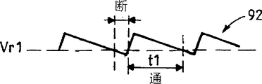
图7为示出了图5或图6所示实施例的操作的一个方面的示意图。FIG. 7 is a schematic diagram illustrating an aspect of the operation of the embodiment shown in FIG. 5 or 6 .
具体实施方式Detailed ways
在图2所示的电池放电器中,将要进行放电的电池(未示出)连接在接线端32和34之间,接线端34为接地端。In the battery discharger shown in Figure 2, the battery to be discharged (not shown) is connected between
电压端32与如电阻器等压降器36的输入端相连,而此压降器的输出端与比较器或电流控制器38的第一输入端381相连,其中38具有将由参考电压产生器40的输出端402提供的参考电压Vr2施加在其上的第二输入端382。The
压降器36的输出端还与第二电压比较器42的第一输入端421相连,该第二电压比较器42包括将由参考电压产生器40的输出端401提供的参考电压Vr1施加在其上的第二输入端422。The output terminal of the voltage dropper 36 is also connected with the first input terminal 421 of the
压降器36的输出端与时间常数元件44相连,该时间常数元件44也与电压比较器42的输出端相连。The output of voltage dropper 36 is connected to a time constant element 44 which is also connected to the output of
最后,压降器36的输出端通过具有与图1所示限流器16相同功能的限流器48与开关电路46的接线端461相连。开关电路的第二接线端462与接地端34相连。开关电路46的控制接线端463与电压比较器42的输出端相连,而且也与电流控制器38的输出端383相连。Finally, the output terminal of the pressure drop 36 is connected to the terminal 461 of the
电路50为与图1所示的LED驱动和显示电路22相类似的LED驱动和显示电路。
压降器或电阻器36具有与时间常数元件44一起、将给定频率强加于参考图1所述的振荡的功能,即由于位于压降器的输出端的电压或位于接线端32的电压(当存在较大的接触电阻时)取决于电流强度,即取决于开关电路46的状态(导通或未导通)的事实而引起的振荡。The voltage dropper or resistor 36 has the function, together with the time constant element 44, of imposing a given frequency on the oscillations described with reference to FIG. When there is a large contact resistance) Oscillations due to the fact that it depends on the intensity of the current, ie on the state of the switching circuit 46 (conducting or not conducting).
当在电池和接线端32、34之间存在较大的接触电阻时,可以省略压降器或电阻器36。The voltage drop or resistor 36 may be omitted when there is a large contact resistance between the battery and the
压降器36或只是接触电阻(当省略压降器36时)与时间常数元件44一起确定与电池电压成正比的振荡频率。Voltage dropper 36 or simply the contact resistance (when voltage dropper 36 is omitted) together with time constant element 44 determines the frequency of oscillation which is proportional to the battery voltage.
在图3所示的实施例中,电流控制器38包括晶体管Ti,该晶体管Ti的发射极与包括两个电阻器R2和R3的分压器的接线端相连。这些电阻器也是参考电压产生器40的组件。In the embodiment shown in FIG. 3, the
参考电压产生器40具有与接线端51相连的输入端,将电池放电器的直流(DC)电源施加在接线端51上。在此示例中,该DC电压源为1.6V。The
产生器40包括位于接线端51和接地端34之间的PNP晶体管Q1,该晶体管Q1的发射极通过电阻器R4与接线端51相连,其集电极与接地端34相连。晶体管Q1的基极通过电阻器R1与接线端51相连,并通过串联电阻器R2和R3接地。晶体管Q1的基极还通过二极管D1与接地端34相连。
第一参考电压Vr1出现在晶体管Q1的发射极,而第二参考电压Vr2出现在电阻器R2和R3之间的连接端,即电流控制器38的晶体管Ti的发射极。A first reference voltage Vr1 is present at the emitter of transistor Q1 and a second reference voltage Vr2 is present at the junction between resistors R2 and R3, ie at the emitter of transistor Ti of
为了滤去来自电源的任何高频噪声,在电池放电器的输入端,将电容器C1连接在接线端51和34之间。To filter out any high frequency noise from the power supply, a capacitor C1 is connected between
电压比较器42包括两个NPN晶体管52和54。这些晶体管52和54的发射极通过电阻器51接地。晶体管52的集电极与接线端51相连。晶体管54的集电极通过电阻器R6与电源接线端51相连。比较器42的输出端为晶体管54的集电极。该晶体管54的基极通过电阻器R7与电阻器36相连。与电阻器36相连的电阻器R7的接线端与时间常数电路44的输入端相连。该时间常数电路44包括连接在电阻器36和开关电路46的控制输入端463之间的电容器C3。
为了使晶体管52不受噪声的影响,将电容器C2设置在晶体管52的基极和地之间。In order to protect the
开关电路46包括PNP型控制晶体管TS1,其发射极与电压端51相连,其集电极通过电容器R9与此电路46的主晶体管TS2的基极相连。晶体管TS2为NPN型,其发射极接地,而集电极通过组成了限流器48的另一个电阻器R15与电阻器36相连。The switching
LED(发光二极管)60的阳极与接线端51相连且阴极通过电阻器R12与LED驱动电路50中的晶体管TL的集电极相连。该晶体管TL的基极通过电阻器R10与晶体管TS1的集电极相连,并通过电阻器R11接地。An anode of an LED (Light Emitting Diode) 60 is connected to the terminal 51 and a cathode is connected to a collector of a transistor TL in the
位于地和开关电路46中的晶体管TS1的集电极之间的电容器C5滤除当晶体管TS1的状态从断变为通时可能会出现的杂散脉冲。Capacitor C5 between ground and the collector of transistor TS1 in switching
电流控制器38包括二极管D3,该二极管的阳极与电阻器32相对的电阻器36的接线端相连,其阴极通过电阻器R13与接地端34相连;此阴极还与晶体管Ti的基极相连,而且电容器C6连接在晶体管Ti的基极和地之间。电流控制器38的二极管D3、电容器C6以及电阻器13将振荡周期内由电池提供的电压转换为在晶体管Ti的基极提供的DC电压。The
图3所示电路的操作如下:The operation of the circuit shown in Figure 3 is as follows:
在此示例中,在参考产生器40的晶体管Q1的发射极处所提供的电压Vr1为1.25V。此数值由二极管D1的阳极电压加上晶体管Q1的基极/发射极的结电压确定。In this example, the voltage Vr1 provided at the emitter of transistor Q1 of
出现在电阻器R2和R3之间的第二参考电压Vr2由这些电阻器的数值和D1的导通电压值确定。在此示例中,此电压Vr2为0.23V。The second reference voltage Vr2 appearing between the resistors R2 and R3 is determined by the values of these resistors and the turn-on voltage value of D1. In this example, this voltage Vr2 is 0.23V.
当电池电压为1.05V时,放电器为断开。When the battery voltage is 1.05V, the discharger is disconnected.
电压比较器42的操作如下:当晶体管54的基极电压低于Vr1(施加在晶体管52的基极上的电压)时,使此晶体管54截止。当此晶体管54的基极电压大于Vr1时,使晶体管54导通,其集电极电压下降。结果,开关电路46的晶体管TS1的基极电压变得低于同一晶体管的发射极减去发射极/基极的电压,因此,该晶体管导通。结果,晶体管TS2(开关电路46的主晶体管)的基极电压增加,该晶体管TS2导通。所以,当电池电压实际上高于参考电压Vr1时,电池通过晶体管TS2进行放电。The operation of the
当开关电路46的晶体管TS1和TS2为通(导通)时,电路50的晶体管TL为“通”。在这种情况下,LED(发光二极管)60产生表示电池正在放电的光信号。Transistor TL of
当电池电压高于参考电压Vr1时,时间常数电路44的电容器C3增加了开关电路46中的开关TS1和TS2的导通时间。在这种情况下,比较器42输出端的电压,即晶体管54的集电极上的电压下降。没有电容器C3,则立刻使晶体管TS1和TS2截止。但是,在晶体管TS1导通和晶体管54导通期间,加载了电容器C3。事实上,在TS1的导通时间期间,根据以下路径对电容器C3进行充电:TS1发射极和基极、电容器C3、电阻器R7、晶体管54的基极-发射极以及电阻器R5。The capacitor C3 of the time constant circuit 44 increases the conduction time of the switches TS1 and TS2 in the
在充电期间,C3的电压增加,并且当TS1的基极电压达到其截止电压(TS1的发射极减去TS1发射极/基极的电压)时,使TS1截止。由于晶体管Ti在高于Vr2的平均电池电压(随后进行解释)获得TS1的基极电流,并且晶体管54在高于Vr1的电池电压(随后进行解释)获得TS1的基极电流,C3的充电时间比放电时间长,即TS1和TS2的导通持续时间较长。During charging, the voltage of C3 increases and turns TS1 off when the base voltage of TS1 reaches its cut-off voltage (the emitter of TS1 minus the voltage of TS1 emitter/base). Since transistor Ti obtains the base current of TS1 at an average battery voltage higher than Vr2 (explained later) and
在使晶体管TS1截止之后,由于电阻器36的压降消失,TS1的基极电压立刻被上拉到接线端51的电压,并且根据下述路径对C3上的电压进行放电:包括晶体管54的集电极-发射极在内的第一路径,以及包括R14、Ti和R3在内的第二路径。Immediately after turning off transistor TS1, the base voltage of TS1 is pulled up to the voltage at
重复C3的充电、放电,直到电池电压变得小于Vr1。Repeat the charge and discharge of C3 until the battery voltage becomes less than Vr1.
此外,当电池电压实质上高于参考电压Vr1时,振荡频率由电容器C3的时间常数、晶体管54和电阻器R5的等效电阻确定;还由晶体管Ti和电阻器R3的等效电阻确定。In addition, when the battery voltage is substantially higher than the reference voltage Vr1, the oscillation frequency is determined by the time constant of the capacitor C3, the equivalent resistance of the
由电流控制器38的二极管D3、电阻器R13和电容器C6提供的已整流电压实际上等于平均电池电压。当出现在晶体管Ti基极上的已整流电压大于参考电压Vr2加上晶体管Ti的基极/发射极的结电压时,使晶体管Ti导通。因此,晶体管TS1的集电极上的电压减小。结果,晶体管TS1的基极上的电压减小,这使得晶体管TS1和TS2整体导通。The rectified voltage provided by diode D3, resistor R13 and capacitor C6 of
该电流控制器还有助于使振荡占空比的导通持续时间更长并减少电池的放电时间。This current controller also helps to make the on-time of the oscillation duty cycle longer and reduce the discharge time of the battery.
但是,当平均电池电压变得低于Vr1时,晶体管Ti保持截止,并不再具有使晶体管TS1和TS2饱和(置于导通状态)的功能。However, when the average battery voltage becomes lower than Vr1, the transistor Ti remains off and no longer has the function of saturating (putting into a conducting state) the transistors TS1 and TS2.
选择电阻器R14的数值以限制TS1的基极电流。The value of resistor R14 is chosen to limit the base current of TS1.
在实施例中,只有当电池电压接近完全放电且断开LED(发光二极管)时,才停止振荡。In an embodiment, the oscillation is stopped only when the battery voltage is close to fully discharged and the LED (Light Emitting Diode) is turned off.
此外,LED(发光二极管)可以用于表示放电过程即将结束,从而,当LED(发光二极管)变暗时,就可以将电池移去了。Additionally, an LED (Light Emitting Diode) can be used to indicate the end of the discharge process, so that the battery can be removed when the LED (Light Emitting Diode) goes dark.
利用适当数值的电容器C3,可以按照以下方式选择二极管的闪烁频率:当电池完全充满时,看不到闪烁,而一旦电池的电量减少闪烁就变得可见,而且当电池接近于完全放电时,以非常低的频率闪烁。With an appropriate value of capacitor C3, the blinking frequency of the diode can be chosen in such a way that the blinking is invisible when the battery is fully charged, becomes visible as soon as the battery is depleted, and becomes visible as soon as the battery is nearly fully discharged. Flashes at very low frequency.
所述电池放电器非常简单。不需要使用如微处理器等复杂IC。减少了放电时间并精确地控制了放电和电压。The battery discharger described is very simple. There is no need to use complex ICs such as microprocessors. Reduced discharge time and precise control of discharge and voltage.
这种电池放电器还可用于检查电池的残余电量,例如通过二极管的闪烁频率来检查。This battery discharger can also be used to check the remaining charge of the battery, for example by the blinking frequency of the diode.
图4所示为一种具有检查功能的电池放电器。在此实施例中,设置开关S1,以便将电路放置在精确对应着图3中电池放电器功能的第一位置(如图4所示)或者放置在其中电容器C4与电容器C3并联且断开电流控制器38的接线端383的第二位置。Figure 4 shows a battery discharger with checking function. In this embodiment, switch S1 is set to place the circuit in the first position (as shown in FIG. 4 ) which corresponds exactly to the function of the battery discharger in FIG. 3 or in which capacitor C4 is connected in parallel with capacitor C3 and disconnects the current flow. The second position of the terminal 383 of the
当断开电流控制器38时,来自要放电的电池的电流最小,且由于C4增大了时间常数,使振荡频率非常低。When the
在实施例中,当电池被完全充满时,振荡频率最大,而当电池被放电时,振荡频率最小。例如,可以在完全电量1.25V时,将此频率选择为43Hz、1.2V时为17Hz、1.15V时为5Hz且1.10V时停止。In an embodiment, the oscillation frequency is at a maximum when the battery is fully charged and at a minimum when the battery is discharged. For example, when the full battery is 1.25V, the frequency can be selected as 43Hz, 17Hz at 1.2V, 5Hz at 1.15V and stop at 1.10V.
可以将该电池放电器与传统的电池充电器相结合。即传统的连续补充电池充电器(慢速充电器)向被充电的电池提供1.6V到1.8V之间的电压,此电压可用于驱动放电器(包括电池检查器),这是因为在电池没有被放电器完全放电之前,并不会使用该充电器。This battery discharger can be combined with a conventional battery charger. That is, the traditional continuous supplementary battery charger (slow charger) provides a voltage between 1.6V and 1.8V to the battery being charged, and this voltage can be used to drive the discharger (including the battery checker), because the battery does not have The charger will not be used until fully discharged by the discharger.
当在电池充电器上具有用于接收充电电压的接触点的印刷电路板上构建如图3和图4所示的电路,并将所述接触点与接线端51和34相连时,可以实现一个完整而廉价的充电/放电结合系统。When constructing the circuit shown in Figures 3 and 4 on a printed circuit board with contacts for receiving the charging voltage on a battery charger and connecting said contacts to
在图5中,与图2中的相应元件功能相同的元件用相同的参考号表示。In FIG. 5, elements having the same function as corresponding elements in FIG. 2 are denoted by the same reference numerals.
在此实施例中,电压比较器82包括接收参考电压Vr1的输入端822和接收对由压降器36所提供的电压进行整流的整流器84的输出的另一个输入端821。In this embodiment, the
在压降器36的输出端和开关46的控制输入端463之间提供了滤波器86。Between the output of the voltage drop 36 and the control input 463 of the switch 46 a
本实施例与图2所示实施例的不同之处在于比较器82提供了实际上没有中间状态的二状态输出信号。因此,开关46实际上也没有中间状态。This embodiment differs from the embodiment shown in FIG. 2 in that
此外,并未提供第二参考Vr2且不能对振荡频率进行修改。正如此后所解释的那样,整流器84的时间常数确定了在每个HF周期中开关46接通的时间。Furthermore, no second reference Vr2 is provided and the oscillation frequency cannot be modified. As will be explained hereinafter, the time constant of the
在图6所示的实施例中,比较器86包括以集成电路形式给出的运算放大器90,而且整流器84包括并联的电容器C13和电阻器R13以及二极管D13。电阻器R5连接在运算放大器的输出端与其一个输入端之间。In the embodiment shown in FIG. 6, the
如图7所示,整流器84提供了锯齿信号92,在HF信号的每个周期的实质部分t1期间,该信号的值高于参考电压Vr1。因此,在HF信号的每个周期的实质部分t1期间,开关46接通。持续时间t1主要由C13和R’13的数值确定。As shown in Figure 7, the
滤波器86包括实际上不会影响持续时间t1的电容器C14。
Claims (13)
Applications Claiming Priority (4)
| Application Number | Priority Date | Filing Date | Title |
|---|---|---|---|
| EP01401988.9 | 2001-07-24 | ||
| EP01401988A EP1280251A1 (en) | 2001-07-24 | 2001-07-24 | Battery discharger |
| EP01402591.0 | 2001-10-08 | ||
| EP01402591.0A EP1280252B1 (en) | 2001-07-24 | 2001-10-08 | Battery discharger |
Publications (2)
| Publication Number | Publication Date |
|---|---|
| CN1528041A true CN1528041A (en) | 2004-09-08 |
| CN1326305C CN1326305C (en) | 2007-07-11 |
Family
ID=26077251
Family Applications (1)
| Application Number | Title | Priority Date | Filing Date |
|---|---|---|---|
| CNB028141490A Expired - Fee Related CN1326305C (en) | 2001-07-24 | 2002-07-15 | Battery discharger |
Country Status (4)
| Country | Link |
|---|---|
| EP (1) | EP1280252B1 (en) |
| JP (1) | JP4191029B2 (en) |
| CN (1) | CN1326305C (en) |
| WO (1) | WO2003010870A2 (en) |
Families Citing this family (6)
| Publication number | Priority date | Publication date | Assignee | Title |
|---|---|---|---|---|
| FR2964507B1 (en) * | 2010-09-07 | 2013-09-06 | St Microelectronics Tours Sas | PROTECTION OF A THIN FILM BATTERY |
| CN112514196A (en) | 2018-07-31 | 2021-03-16 | 赛昂能源有限公司 | Multi-path charging and discharging battery management system |
| US11424492B2 (en) | 2019-10-31 | 2022-08-23 | Sion Power Corporation | System and method for operating a rechargeable electrochemical cell or battery |
| US11056728B2 (en) * | 2019-10-31 | 2021-07-06 | Sion Power Corporation | System and method for operating a rechargeable electrochemical cell or battery |
| US12580394B2 (en) | 2020-09-01 | 2026-03-17 | Sion Power Corporation | Multiplexed battery management system |
| US12374913B2 (en) | 2021-02-05 | 2025-07-29 | Sion Power Corporation | Charge/discharge management in electrochemical cells, including partial cycle control |
Family Cites Families (4)
| Publication number | Priority date | Publication date | Assignee | Title |
|---|---|---|---|---|
| US4755733A (en) * | 1987-02-03 | 1988-07-05 | Irsst Institut De Recherche En Sante Et En Securite Du Travail Du Quebec | Battery charging and cycling devices |
| CN87201161U (en) * | 1987-03-23 | 1987-11-25 | 何家华 | Automatic control device for storage battery charging or discharging |
| JPH0568347A (en) * | 1991-09-09 | 1993-03-19 | Sony Corp | Battery discharge control circuit |
| FR2783979B1 (en) * | 1998-09-28 | 2000-11-10 | Cit Alcatel | PORTABLE ELECTRONIC DEVICE WITH BATTERY DISCHARGE CONTROL CIRCUIT, AND ASSOCIATED METHOD |
-
2001
- 2001-10-08 EP EP01402591.0A patent/EP1280252B1/en not_active Expired - Lifetime
-
2002
- 2002-07-15 JP JP2003516140A patent/JP4191029B2/en not_active Expired - Fee Related
- 2002-07-15 CN CNB028141490A patent/CN1326305C/en not_active Expired - Fee Related
- 2002-07-15 WO PCT/EP2002/007862 patent/WO2003010870A2/en not_active Ceased
Also Published As
| Publication number | Publication date |
|---|---|
| WO2003010870A2 (en) | 2003-02-06 |
| EP1280252B1 (en) | 2015-04-01 |
| JP4191029B2 (en) | 2008-12-03 |
| EP1280252A2 (en) | 2003-01-29 |
| JP2004536547A (en) | 2004-12-02 |
| WO2003010870A3 (en) | 2004-02-26 |
| CN1326305C (en) | 2007-07-11 |
| EP1280252A3 (en) | 2004-03-03 |
Similar Documents
| Publication | Publication Date | Title |
|---|---|---|
| CN1167168C (en) | Battery charger, battery pack, and charging method for secondary battery | |
| CN1197229C (en) | DC-DC converter | |
| CN100350711C (en) | Charging rate regulating circuit for battery group | |
| CN1622438A (en) | Power supply circuit | |
| CN1045857C (en) | Camera's rechargeable battery system | |
| JP5996601B2 (en) | AC type LED lamp and control method thereof | |
| CN1357957A (en) | Charging method and charger | |
| CN102210091B (en) | An electronic circuit arranged to control the voltage applied to a load | |
| CN1525620A (en) | Battery charger and method thereof | |
| CN1038085C (en) | Electricity charging device | |
| CN1591115A (en) | Power supply apparatus | |
| CN1441526A (en) | Charging circuit and battery charger | |
| TWI507081B (en) | Driving circuit and control circuit for powering light source | |
| CN1670792A (en) | Light emitting element driving device and portable apparatus equipped with light emitting elements | |
| CN104584687A (en) | Arrangement and method for controlling light-emitting diodes in accordance with an input voltage level, by means of a capacitor and switch | |
| CN1578046A (en) | Charging circuit and charger using the same | |
| CN1111935C (en) | charging device | |
| CN1745513A (en) | Control system of generator for vehicle | |
| CN1507142A (en) | Switching power supply unit | |
| CN1722032A (en) | Portable photographing apparatus and power switching control method | |
| CN1326305C (en) | Battery discharger | |
| CN1467557A (en) | Power supply circuit for camera | |
| JP3999719B2 (en) | Charging circuit for dry cell phone | |
| JPS62107641A (en) | Charge control circuit | |
| JP2882047B2 (en) | Vehicle charging control device |
Legal Events
| Date | Code | Title | Description |
|---|---|---|---|
| C06 | Publication | ||
| PB01 | Publication | ||
| C10 | Entry into substantive examination | ||
| SE01 | Entry into force of request for substantive examination | ||
| C14 | Grant of patent or utility model | ||
| GR01 | Patent grant | ||
| CF01 | Termination of patent right due to non-payment of annual fee | ||
| CF01 | Termination of patent right due to non-payment of annual fee |
Granted publication date: 20070711 Termination date: 20190715 |