CN1528049A - Optimizing the Operating Point of Transmitter Power Amplifiers in Mobile Stations - Google Patents
Optimizing the Operating Point of Transmitter Power Amplifiers in Mobile Stations Download PDFInfo
- Publication number
- CN1528049A CN1528049A CNA028132041A CN02813204A CN1528049A CN 1528049 A CN1528049 A CN 1528049A CN A028132041 A CNA028132041 A CN A028132041A CN 02813204 A CN02813204 A CN 02813204A CN 1528049 A CN1528049 A CN 1528049A
- Authority
- CN
- China
- Prior art keywords
- operating point
- controlling signal
- power
- switch
- oblique wave
- Prior art date
- Legal status (The legal status is an assumption and is not a legal conclusion. Google has not performed a legal analysis and makes no representation as to the accuracy of the status listed.)
- Pending
Links
Images

Classifications
-
- H—ELECTRICITY
- H03—ELECTRONIC CIRCUITRY
- H03G—CONTROL OF AMPLIFICATION
- H03G3/00—Gain control in amplifiers or frequency changers
- H03G3/20—Automatic control
- H03G3/30—Automatic control in amplifiers having semiconductor devices
- H03G3/3036—Automatic control in amplifiers having semiconductor devices in high-frequency amplifiers or in frequency-changers
- H03G3/3042—Automatic control in amplifiers having semiconductor devices in high-frequency amplifiers or in frequency-changers in modulators, frequency-changers, transmitters or power amplifiers
- H03G3/3047—Automatic control in amplifiers having semiconductor devices in high-frequency amplifiers or in frequency-changers in modulators, frequency-changers, transmitters or power amplifiers for intermittent signals, e.g. burst signals
Landscapes
- Transmitters (AREA)
- Amplifiers (AREA)
Abstract
在本案中,系使用一种附加的控制电压,其振幅系为在现行时槽期间所需的最大增益的一个量度,甚至可以是在现用时槽开始之前,被提供给传送器功率放大器,以为了提供给个别操作点设定达到降低功率消耗可能性的目的。
In this case, an additional control voltage is used, the amplitude of which is a measure of the maximum gain required during the current time slot, and may even be provided to the transmitter power amplifier before the start of the current time slot, in order to provide individual operating point settings to reduce the possibility of power consumption.
Description
本案系关于如在权利要求独立项所述之一种用以在一行动台中最佳化一传送器功率放大器操作点之装置及其方法。The present case relates to a device and method for optimizing the operating point of a transmitter power amplifier in a mobile station as described in the independent claim.
在行动台(MS)的传送装置中,传送器功率放大器(PA)系在传送讯号被提供到天线之前,被用来放大由传送资料所调变的传送讯号。为了进行此步骤所需要的能量系由包含在MS中的电池而来,所需要的RMS传送功率系取决于参数的数量而定,例如从基地台起的MS距离、无线电信道衰退、无线电信道的噪声、无线电信道的频谱特性以及传送方法等等。为了节省能量也因而为了达到尽可能长的电池寿命,传送功率也对应地适应于一个或是多个的这些参数。In a mobile station (MS) transmission device, a transmitter power amplifier (PA) is used to amplify a transmit signal modulated by transmit data before the transmit signal is supplied to an antenna. The energy required to perform this step is derived from the battery contained in the MS, and the required RMS transmit power depends on a number of parameters such as the MS distance from the base station, radio channel fading, radio channel Noise, spectral characteristics of radio channels, transmission methods, etc. In order to save energy and thus to achieve the longest possible battery life, the transmission power is also adapted correspondingly to one or more of these parameters.
在应用时分多任务(time division multiplex,TDM)方法中,传送功率通常是针对每个时槽而分别地建立,且对于时槽的持续期间来说,其系为固定不变的。通常,传送功率可在步骤中被选定且不可超出最大的传送功率,而传送功率放大器则在现用时槽之间(activetime slot)被关闭。In applying time division multiplex (TDM) methods, the transmit power is usually established separately for each time slot and is constant for the duration of the time slot. Usually, the transmit power can be selected in steps and the maximum transmit power cannot be exceeded, and the transmit power amplifier is turned off between active time slots.
在现用时槽开始之前,传送功率放大器被开启,而增益则藉由在MS中所产生的一控制讯号v(t),从最小值开始,渐渐地增加直到达到想要的值,而以此种方式,并没有干扰毗连信道的噪声频谱发生。在此增益或是功率斜波之后的偏差系藉由功率斜波控制装置来决定,在时槽的活动阶段期间,增益几乎是保持固定不变,而在结束时则再次的降低。Before the start of the active time slot, the transmit power amplifier is turned on, and the gain is gradually increased from the minimum value until reaching the desired value by a control signal v(t) generated in the MS. In this way, no interference with the noise spectrum of adjacent channels occurs. The gain or deviation after the power ramp is determined by the power ramp control means. During the active phase of the time slot, the gain remains almost constant and decreases again at the end.
为了使传送功率放大器产生在每个状况中所需要的增益,其操作点(AP)必须相对应地选定,因为在一个现用时槽开始之时,其并无法与在时槽的现用部分中最大增益Vmax所需的控制讯号明显的区分,而必须假定其也可以是可被设定的最大增益V0。为了此等理由,AP必须从一开始被选定,以这样的方式,传送器功率放大器可产生最大可能增益。不过,在大部分的状况中,在一现用时槽内并不需要最大可能增益V0。In order for the transmit power amplifier to produce the required gain in each situation, its operating point (AP) must be selected accordingly, because at the beginning of an active time slot, it cannot be compared with the active part of the time slot. A clear distinction is made between the control signal required for the maximum gain V max , which must also be assumed to be the maximum gain V 0 that can be set. For these reasons, the AP has to be selected from the beginning in such a way that the transmitter power amplifier can produce the maximum possible gain. However, in most cases, the maximum possible gain V 0 within an active time slot is not required.
然而,该传送器功率放大器的基本电流消耗系取决于所选定的AP,所选定的AP越高,则电流消耗也就越大。首先,假如在低的传送功率下被选定的AP为不必要的高,其效应则相对的低且电池也会被不必要的加载,也因而减短了电池的寿命。However, the basic current consumption of the transmitter PA depends on the selected AP, the higher the selected AP, the greater the current consumption. First, if the selected AP is unnecessarily high at low transmit power, the effect is relatively low and the battery will be unnecessarily loaded, thus reducing battery life.
因此,本案其中的一个目的为具体指定一种用以在一行动台中最佳化一传送器功率放大器(60)操作点之装置及其方法,藉由此种装置与方法可以改进行动无线电台的效率,且同时可以使所需要的传送功率一直都是在可利用的状态。Therefore, one of the objects of the present case is to specify an apparatus and method for optimizing the operating point of a transmitter power amplifier (60) in a mobile station, by which apparatus and method the performance of mobile radio stations can be improved. Efficiency, and at the same time, the required transmission power can be always available.
此目的可藉由权利要求独立项的特征来达成,而有益的实施例与发展则在附属项中来进一步具体指定。This object is achieved by the features of the independent claims, while advantageous embodiments and developments are further specified in the dependent claims.
本案主要的方面在于使用一种附加的控制电压,其振幅系为在现行时槽期间所需的最大增益的一个量度,甚至可以说是在现用时槽开始之前被提供给传送器功率放大器,为了提供给操作点设定以达到降低功率消耗可能性的目的。The main aspect of this case is the use of an additional control voltage whose amplitude is a measure of the maximum gain required during the active time slot, even before the active time slot begins, to the transmitter power amplifier, in order to Provided for operating point setting to achieve the purpose of reducing the possibility of power consumption.
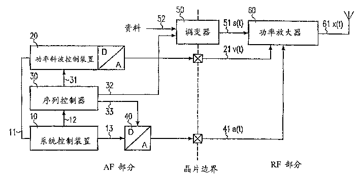
根据第1图本案的装置之一般实施例,其具有一D/A切换器40,此D/A切换器40在其输入端针对每一个时槽接收来自一系统控制装置10至少一个数字值13,其系在D/A切换器40的输出端以一模拟值41而被输出至功率放大器60,并藉由此讯号而及时与序列控制器同步化。According to the general embodiment of the device of the present case in Fig. 1, it has a D/A switcher 40, and this D/A switcher 40 receives at its input terminal at least one digital value 13 from a system control device 10 for each time slot , which is output to the power amplifier 60 as an analog value 41 at the output terminal of the D/A switch 40, and is synchronized with the sequence controller in time by this signal.
此实施例系展现出以下的优点:This embodiment exhibits the following advantages:
a)具体指定功率斜波的形状与振幅并藉由该连接11将功率斜波传送至功率斜波控制装置20的系统控制器10,其因而可以决定在时槽中所需要的最大增益Vmax与其所提供至该D/A切换器的数字值13。a) specifying the shape and amplitude of the power ramp and sending the power ramp via the connection 11 to the system controller 10 of the power ramp control device 20, which can thus determine the maximum gain V max required in the time slot Instead of the digital value 13 provided to the D/A switch.
b)可在时槽开始之前设定操作点。b) The operating point can be set before the time slot starts.
c)在新的模拟值41被输出的正确时间,其可藉由到序列控制器30的链路33而与功率斜波以及时槽精确地同步化。c) At the correct time when the new analog value 41 is output, which can be precisely synchronized with the power ramp and the time slot by the link 33 to the sequence controller 30 .
d)此种设置可被完全地整合在其所控制的芯片中。d) Such a setup can be fully integrated in the chip it controls.
再者,亦可见到以下另外的特征:Furthermore, the following additional features can also be seen:
a)因为增益仍然仅由讯号v(t)决定,系统也与不具有个别设定操作点兼容性的功率放大器兼容。a) Since the gain is still only determined by the signal v(t), the system is also compatible with power amplifiers that do not have compatibility with individual set operating points.
b)在现用时槽间的执行期间,通常在具有功率斜波控制装置与功率放大器的状况中,D/A切换器可被关闭以节省电流。b) During execution between active slots, typically in the case with power ramp control and power amplifiers, the D/A switch can be turned off to save current.
因此,一个时槽特定操作点的最佳化可藉由本案而来执行。行动无线电台的传送器功率放大器操作点,其可针对每个时槽而进行设定,而其系依照在此时槽中所需的传送功率与所需的该传送器功率放大器增益来进行设定。因此,针对每个时槽的传送器功率放大器操作点,其并不需要被设定在比在此时槽中所需要的最大增益Vmax为高的位准。Therefore, optimization of a slot-specific operating point can be performed by the present invention. The transmitter power amplifier operating point of the mobile radio station, which can be set for each time slot, is set according to the required transmit power in the time slot and the required gain of the transmitter power amplifier Certainly. Therefore, the transmitter PA operating point for each time slot does not need to be set at a higher level than the maximum gain V max required in that time slot.
根据本案,甚至在功率斜波开始之前来进行传送器功率放大器操作点的设定是可能的。再者,具有时间与增益振幅的偏差只由控制讯号v(t)而建立。为了实施本案,最多仅需要一个另外的讯号输出。According to the present case, it is possible to set the operating point of the transmitter power amplifier even before the start of the power ramp. Again, the deviation with time and gain amplitude is only established by the control signal v(t). For the implementation of the present case, at most only one further signal output is required.
根据本案的操作点之最佳化其系特别适合在支持GSM、EDGE或者是TIA/EIA-136(IS-136)的标准。According to the optimization of the operating point in this case, it is especially suitable for supporting GSM, EDGE or TIA/EIA-136 (IS-136) standards.
在之后的内容中,本案将藉由已经概述的较佳实施例,并结合图标来做更详细的说明,其中:In the following content, this case will be described in more detail with the preferred embodiment already outlined and combined with icons, wherein:
第1图系显示根据本案用以最佳化操作点之装置的较佳实施例之方块图;Figure 1 is a block diagram showing a preferred embodiment of the device for optimizing the operating point according to the present invention;
第2图系显示不同时槽序列的讯号v(t)与A(t)之时序图;以及Figure 2 is a timing diagram showing signals v(t) and A(t) for different time slot sequences; and
第3图系显示设定操作点较佳实施例之图标。Figure 3 is an icon showing a preferred embodiment of setting the operating point.
第1图系显示包含本案以及另外特定实施例之最普遍类型所有需要的组件,并显示用以了解此系统好处的方块图。Figure 1 is a block diagram showing the most general type of all required components comprising this and other specific embodiments and showing the benefits of this system.
第1图中的装置首先是包含一系统控制装置10,此系统控制装置10系传送功率斜波11的资料到功率斜波控制装置20,以及同步信息12秩序列控制器30。该功率斜波控制装置20系藉由D/A之协助,在藉由透过序列控制器30的同步信息31所指定的时间而依次将功率斜波以一模拟讯号之方式而输出。此讯号v(t)21被提供至功率放大器60并决定其增益以及该传送讯号x(t)61的功率位准。The device in Fig. 1 firstly includes a system control device 10, the system control device 10 transmits the data of the power ramp 11 to the power ramp control device 20, and the synchronization information 12 to the sequence controller 30. With the help of D/A, the power ramp control device 20 sequentially outputs the power ramp as an analog signal at the time specified by the synchronization information 31 of the sequence controller 30 . This signal v(t) 21 is provided to a power amplifier 60 and determines its gain and the power level of the transmitted signal x(t) 61 .
从资料52,其系透过同步信息32而与功率斜波同步,调变器50而形成调变讯号,此调变讯号系被功率放大器60放大并且以传送讯号x(t)61被输出。From the data 52 , which is synchronized with the power ramp by means of the synchronization information 32 , the modulator 50 forms a modulated signal which is amplified by the power amplifier 60 and output as the transmit signal x(t) 61 .
如根据本案的延伸,在第1图中所显示的装置包含一D/A切换器40,在其输入端接收来自系统控制10的数字值13,而在其已被序列控制器30要求像这样进行(例如经由同步线路33的脉冲)之后,在输出端以一模拟讯号或是电压a(t)41的方式输出。讯号a(t)相当于关联的时槽中所需的最大增益vmax,直到在输出端出现一个新的数字值以及该序列控制器以发送出一脉冲时,其仍然是没有改变。假如该D/A切换器被关闭时,会输出a(t)=0的值。As an extension of the present case, the device shown in Figure 1 comprises a D/A switcher 40 receiving at its input a digital value 13 from the system control 10, where it has been requested by the sequence controller 30 like this After this is done (for example via a pulse of the synchronous line 33 ), it is output as an analog signal or voltage a(t) 41 at the output. The signal a(t) corresponds to the desired maximum gain vmax in the associated time slot, which remains unchanged until a new digital value appears at the output and the sequence controller sends a pulse. If the D/A switch is turned off, a(t)=0 will be output.
讯号a(t)系被提供至该功率放大器60,在此处其系被用来做为设定操作点的参数及/或其它放大器参数。Signal a(t) is provided to the power amplifier 60 where it is used as a parameter for setting the operating point and/or other amplifier parameters.
第2图系藉由实例来显示针对不同时槽序列之讯号v(t)与a(t)与时间之简化的变化。为了使功率放大器在相对应的操作点作用,讯号a(t)系在功率斜波开始之前被输出。在连续的现用时槽的状况中,操作点在切换阶段期间被关闭。Figure 2 shows by way of example the simplified variation of signals v(t) and a(t) versus time for different time slot sequences. In order for the power amplifier to function at the corresponding operating point, the signal a(t) is output before the start of the power ramp. In the case of consecutive active slots, the operating point is closed during the switching phase.
t1-t4时间具有以下阶段的特征The t1-t4 time is characterized by the following phases
t1增加与减少增益至Vmax,1的功率斜波之开始t1 Increase and decrease gain to V max, start of power ramp of 1
t2功率斜波再次增加至Vmax,2之开始t2 The power ramp increases again to V max, the beginning of 2
t3功率斜波再次从Vmax,2减少至Vmax,3之开始t3 The power ramp decreases again from V max, 2 to the start of V max, 3
t3传送序列的终止Termination of t3 transmission sequence
第3图系藉由实例来显示功率放大器60操作点的设定,以及针对第2图中所显示的操作状态之传送讯号调变范围,<s>微调变讯号s(t)51的最大振幅。Figure 3 is an example to show the setting of the operating point of the power amplifier 60, and the transmission signal modulation range for the operating state shown in Figure 2, <s> the maximum amplitude of the fine-tuning signal s(t) 51 .
Claims (20)
Applications Claiming Priority (4)
| Application Number | Priority Date | Filing Date | Title |
|---|---|---|---|
| DE10131654.2 | 2001-06-29 | ||
| DE2001131654 DE10131654A1 (en) | 2001-06-29 | 2001-06-29 | Mobile base station power amplifier has separate operating point control |
| US09/895,595 US7031677B2 (en) | 2001-06-29 | 2001-06-29 | Optimization of the operating point of power amplifiers in mobile stations |
| US09/895,595 | 2001-06-29 |
Publications (1)
| Publication Number | Publication Date |
|---|---|
| CN1528049A true CN1528049A (en) | 2004-09-08 |
Family
ID=26009614
Family Applications (1)
| Application Number | Title | Priority Date | Filing Date |
|---|---|---|---|
| CNA028132041A Pending CN1528049A (en) | 2001-06-29 | 2002-06-07 | Optimizing the Operating Point of Transmitter Power Amplifiers in Mobile Stations |
Country Status (5)
| Country | Link |
|---|---|
| EP (1) | EP1402632B1 (en) |
| CN (1) | CN1528049A (en) |
| AT (1) | ATE336103T1 (en) |
| DE (1) | DE50207805D1 (en) |
| WO (1) | WO2003005600A2 (en) |
Family Cites Families (3)
| Publication number | Priority date | Publication date | Assignee | Title |
|---|---|---|---|---|
| EP0563125A4 (en) * | 1990-12-17 | 1997-02-26 | Motorola Inc | Dynamically biased amplifier |
| US5426641A (en) * | 1994-01-28 | 1995-06-20 | Bell Communications Research, Inc. | Adaptive class AB amplifier for TDMA wireless communications systems |
| JPH1155131A (en) * | 1997-08-06 | 1999-02-26 | Nec Corp | Wireless transmission power control device |
-
2002
- 2002-06-07 CN CNA028132041A patent/CN1528049A/en active Pending
- 2002-06-07 EP EP02750780A patent/EP1402632B1/en not_active Expired - Lifetime
- 2002-06-07 AT AT02750780T patent/ATE336103T1/en not_active IP Right Cessation
- 2002-06-07 WO PCT/DE2002/002089 patent/WO2003005600A2/en not_active Ceased
- 2002-06-07 DE DE50207805T patent/DE50207805D1/en not_active Expired - Lifetime
Also Published As
| Publication number | Publication date |
|---|---|
| DE50207805D1 (en) | 2006-09-21 |
| EP1402632B1 (en) | 2006-08-09 |
| WO2003005600A3 (en) | 2003-11-06 |
| ATE336103T1 (en) | 2006-09-15 |
| WO2003005600A2 (en) | 2003-01-16 |
| EP1402632A2 (en) | 2004-03-31 |
Similar Documents
| Publication | Publication Date | Title |
|---|---|---|
| EP1396932B1 (en) | Wireless communication apparatus | |
| CN1307786C (en) | Power amplifying circuit and method for supplying power by multiple required power output level | |
| CN1875594B (en) | Dual mode multi-slot EGPRS transmitter | |
| CN1027848C (en) | Power amplifier ramp up method and apparatus | |
| US8428181B2 (en) | Method and apparatus for optimizing transmitter power efficiency | |
| US7342955B2 (en) | Apparatus and method for mobile communication device transmission | |
| US20050266811A1 (en) | Ramp signal with boost portion preceding a time slot | |
| CN1274204A (en) | Radio communicating device and emitting power control method for radio communicating device | |
| CN1110125C (en) | device and method for compensating phase distortion | |
| US7805116B2 (en) | Gain control methods for wireless devices and transmitters | |
| CN1162374A (en) | Method and apparatus for linear transmitter | |
| CN1765063B (en) | Power saving in a transmitter | |
| JP3323174B2 (en) | TDMA digital radio transmitter | |
| US8068797B2 (en) | Gain control methods for wireless devices and transmitters | |
| GB2287595A (en) | Method for amplitude training in a linear power amplifier for a transmitter | |
| US8000665B2 (en) | Systems and methods for adjusting headroom of a power amplifier | |
| CN1524342A (en) | Power Control of Non-Constant Envelope Modulation | |
| US7031677B2 (en) | Optimization of the operating point of power amplifiers in mobile stations | |
| KR20060122818A (en) | A transmitter, a system including a base station and a transmitter, and a method of transmitting the transmitter | |
| US20070080746A1 (en) | Glitch-free controllable rf power amplifier | |
| CN1756114A (en) | Automatic power adjusting apparatus and method for repeater in TDD system | |
| JP2000295119A (en) | Wireless transmitter | |
| JPH05129860A (en) | Power amplifier and transmitter | |
| JP3758967B2 (en) | Transmission power control circuit in radio transmitter | |
| CN1146158C (en) | Time Division Multiple Access System Wireless Equipment and Synthesizer Output Level Adjusting Circuit |
Legal Events
| Date | Code | Title | Description |
|---|---|---|---|
| C06 | Publication | ||
| PB01 | Publication | ||
| C10 | Entry into substantive examination | ||
| SE01 | Entry into force of request for substantive examination | ||
| C02 | Deemed withdrawal of patent application after publication (patent law 2001) | ||
| WD01 | Invention patent application deemed withdrawn after publication |