CN1551951A - Improved pitot tube insert - Google Patents
Improved pitot tube insert Download PDFInfo
- Publication number
- CN1551951A CN1551951A CNA028173805A CN02817380A CN1551951A CN 1551951 A CN1551951 A CN 1551951A CN A028173805 A CNA028173805 A CN A028173805A CN 02817380 A CN02817380 A CN 02817380A CN 1551951 A CN1551951 A CN 1551951A
- Authority
- CN
- China
- Prior art keywords
- inlet
- pitot tube
- opening
- lip
- rotor
- Prior art date
- Legal status (The legal status is an assumption and is not a legal conclusion. Google has not performed a legal analysis and makes no representation as to the accuracy of the status listed.)
- Granted
Links
Images


Classifications
-
- F—MECHANICAL ENGINEERING; LIGHTING; HEATING; WEAPONS; BLASTING
- F04—POSITIVE - DISPLACEMENT MACHINES FOR LIQUIDS; PUMPS FOR LIQUIDS OR ELASTIC FLUIDS
- F04D—NON-POSITIVE-DISPLACEMENT PUMPS
- F04D1/00—Radial-flow pumps, e.g. centrifugal pumps; Helico-centrifugal pumps
- F04D1/12—Pumps with scoops or like paring members protruding in the fluid circulating in a bowl
Landscapes
- Engineering & Computer Science (AREA)
- Mechanical Engineering (AREA)
- General Engineering & Computer Science (AREA)
- Structures Of Non-Positive Displacement Pumps (AREA)
Abstract
一种用于离心泵的皮托管(26)的皮托管入口(40),该皮托管入口在输送含有固体的流体且固体沿泵的转子(14)的内表面出现积聚时可提高泵的效率。该皮托管入口可接触和除去积聚在转子中的固体,以便减小对转子的阻碍作用,从而减少皮托管的磨损并提高泵的效率。
A pitot tube inlet (40) for a pitot tube (26) of a centrifugal pump to increase pump efficiency when delivering fluids containing solids that accumulate along the inner surface of the pump's rotor (14) . The pitot tube inlet contacts and removes solids accumulated in the rotor to reduce drag on the rotor, thereby reducing wear on the pitot tube and increasing pump efficiency.
Description
技术领域technical field
本申请涉及一种皮托管式离心泵,尤其涉及一种用于接触和除去集聚在泵转子上固体的改进的皮托管的入口开口。This application relates to a pitot tube centrifugal pump, and more particularly to an improved inlet opening of the pitot tube for contacting and removing solids accumulated on the pump rotor.
背景技术Background technique
在低流量/高压力的泵工业中使用皮托管式离心泵是众所周知的。皮托管式离心泵通常设有一个容纳在泵的壳体内的闭合转子。皮托管组件经转子的中心开口设置并固定在泵的壳体中。一个皮托管组件的皮托管臂设置在该转子内并且相对于泵的轴线沿径向定位。当转子绕皮托管臂旋转时,该皮托管臂保持静止不动。The use of pitot tube centrifugal pumps is well known in the low flow/high pressure pump industry. Pitot tube centrifugal pumps generally have a closed rotor housed within the pump casing. The pitot tube assembly is positioned through the central opening of the rotor and secured in the pump housing. A pitot tube arm of a pitot tube assembly is disposed within the rotor and positioned radially relative to the axis of the pump. The pitot arm remains stationary while the rotor rotates around the pitot arm.
在操作中,流体沿旋转轴经过位于转子壳体内沿径向定位的流体通道流入到转子内。当转子旋转时,这些进入到转子的内部空间中的流体将吸收动量并承受离心力的作用。In operation, fluid flows into the rotor along the axis of rotation through radially positioned fluid passages located within the rotor housing. As the rotor rotates, this fluid entering the interior space of the rotor absorbs momentum and is subjected to centrifugal force.
皮托管臂设有一个容纳流体的入口,而且该皮托管的入口开口设置在转子的内边缘或者内径附近。当流体射向转子的内边缘时,其就会经该皮托管的内部通道流到皮托管的入口中并通过排放出口排出到泵外。The pitot tube arm is provided with an inlet to contain the fluid, and the inlet opening of the pitot tube is provided near the inner edge or inner diameter of the rotor. As the fluid hits the inner edge of the rotor, it flows through the internal channel of the pitot tube into the inlet of the pitot tube and exits the pump through the discharge outlet.
传统上,在泵中所使用的皮托管及其设有的入口开口是浇铸和机加工制成的。但,在泵连续使用之后,尤其是当泵输送研磨流体时,该流体对皮托管的开口的撞击将引起该入口的磨损甚至严重地影响泵的效率。而且,皮托管臂必须整体被更换,这样就非常贵而且增加了生产费用。Traditionally, the pitot tubes used in pumps and the inlet openings provided with them are cast and machined. However, after continuous use of the pump, especially when the pump is delivering abrasive fluid, the impact of the fluid on the opening of the pitot tube will cause wear of the inlet and even seriously affect the efficiency of the pump. Furthermore, the pitot arm must be replaced in its entirety, which is very expensive and increases production costs.
针对皮托管的插入件的研究以及该插入件的优点首先出现在发明人Shaw提出的美国专利No.5,997,243(1999.12.7公开并已经转让给本申请的相同受让人)中。在此,将美国专利No.5,997,243引入作为参考。专利5,997,243公开了一种皮托管入口的插入件,该插入件允许皮托管的入口开口在因使用而磨损或损坏之后被更换掉。该入口插入件不需要更换整个皮托管臂因而降低了生产费用。在专利5,997,243中描述的皮托管插入件提高了泵的效率并降低或者消除了皮托管入口的空穴现象和磨损。The study of an insert for a pitot tube and the advantages of this insert first appeared in US Patent No. 5,997,243 (published on December 7, 1999 and assigned to the same assignee of the present application) by inventor Shaw. US Patent No. 5,997,243 is hereby incorporated by reference. Patent 5,997,243 discloses a pitot tube inlet insert which allows the inlet opening of the pitot tube to be replaced after wear or damage from use. The inlet insert does not require replacement of the entire pitot tube arm thereby reducing production costs. The pitot tube insert described in patent 5,997,243 increases pump efficiency and reduces or eliminates cavitation and wear at the pitot tube inlet.
皮托管泵中常出现的另一个问题上面并没有提及到。即,当泵送的流体含有颗粒物质或者固体时,流体和固体对皮托管的撞击将使其受到非常严重的损害,尤其是对头部造成损害。因此,当流体中存在固体时,在离心力的作用下,该固体投射到转子的内圆周表面上并且能在转子上聚集起来。该积聚的固体聚集在旋转转子的内圆周表面上,然后,由于转子旋转而与静止的皮托管发生撞击并增加了对转子的阻碍作用。因此,损失了泵效率。固体对入口的撞击还使皮托管臂及其入口受到损害。Another problem that often occurs with pitot tube pumps is not mentioned above. That is, when the pumped fluid contains particulate matter or solids, the impact of the fluid and solids on the pitot tube can cause very serious damage, especially to the head. Therefore, when solids are present in the fluid, the solids are projected onto the inner circumferential surface of the rotor and can collect on the rotor under centrifugal force. The accumulated solids collect on the inner peripheral surface of the rotating rotor and then, as the rotor rotates, collide with the stationary pitot tube and increase the resistance to the rotor. Therefore, pump efficiency is lost. Impact of solids on the inlet also damages the pitot arm and its inlet.
因此,在现有技术中,当皮托管泵用于输送的液体含有积聚在转子内的固体时,希望能提供一种具有较高泵效率的皮托管入口,而且希望提供一种皮托管入口插入件,该插入件能在上述条件下提供较高的泵效率,而且还具有以较低费用容易地更换的优点。Therefore, in the prior art, when a pitot tube pump is used to deliver liquid containing solids accumulated in the rotor, it is desirable to provide a pitot tube inlet with higher pump efficiency, and it is desirable to provide a pitot tube inlet insertion The insert provides high pump efficiency under the above conditions and has the advantage of being easily replaceable at relatively low cost.
发明内容Contents of the invention
本发明提供了一种皮托管入口,该皮托管入口能接触和除去积聚在离心泵转子的内圆周表面上的固体,从而提高泵的生产效率。尽管本发明主要是针对用于除去转子的内圆周表面上的固体的皮托管入口插入件来进行描述的,但本发明的设计和结构特征同样可应用于以传统方式一体浇铸的皮托管。The present invention provides a pitot tube inlet capable of contacting and removing solids accumulated on the inner circumferential surface of a rotor of a centrifugal pump, thereby improving the production efficiency of the pump. Although the invention is primarily described with respect to a pitot tube inlet insert for removing solids from the inner circumferential surface of a rotor, the design and structural features of the invention are equally applicable to conventionally integrally cast pitot tubes.
本发明的皮托管入口通常包括一个开口,将该开口设置并设计成能容纳来自皮托管泵的转子的边缘部分的流体;以及一个环绕着该开口的至少一部分圆周或者边缘的唇部,将该唇部设计成接触和除去易于积聚和粘附在转子的内圆周表面上的固体。该皮托管入口的唇部通常指向远离该开口的方向,从而提供一个类似铲子的部分,该部分能够从转子的内圆周表面上铲除固体。The Pitot tube inlet of the present invention generally includes an opening positioned and designed to receive fluid from the edge portion of the rotor of the Pitot tube pump; and a lip surrounding at least a portion of the circumference or edge of the opening, the The lips are designed to contact and remove solids that tend to accumulate and adhere to the inner circumferential surface of the rotor. The lip of the pitot tube inlet generally points away from the opening, thereby providing a scoop-like portion capable of scooping up solids from the inner circumferential surface of the rotor.
皮托管入口的唇部还设有一个弯曲的内表面,该内表面围绕该入口的开口而设置从而将固体引入到皮托管的开口中以便排出。该内表面的曲率不仅便于将固体引入到皮托管内,而且通过以一种可减少皮托管入口内遭受到的通常磨损的方式来有效地偏转固体和液体从而增加了皮托管入口的使用寿命。只要该唇部能接触和除去转子的内表面上积聚的固体,就可对唇部的大小、形状、尺寸、角度、延伸范围和/或圆周延伸范围进行改变,以便减小或者消除对转子的阻碍作用从而提高泵的工作效率。The lip of the pitot tube inlet is also provided with a curved inner surface disposed around the opening of the inlet to introduce solids into the opening of the pitot tube for discharge. The curvature of the inner surface not only facilitates the introduction of solids into the pitot tube, but also increases the useful life of the pitot tube inlet by effectively deflecting solids and liquids in a manner that reduces the typical wear experienced within the pitot tube inlet. The size, shape, dimension, angle, extent and/or circumferential extent of the lip can be varied so as to reduce or eliminate damage to the rotor so long as the lip is capable of contacting and removing solids accumulated on the inner surface of the rotor. Blocking effect to improve the efficiency of the pump.
附图说明Description of drawings
在附图中,示出了目前认为操作本发明的最好模式:In the accompanying drawings, the presently considered best mode of operating the invention is shown:
图1是皮托管式离心泵的一部分的横截面视图,示出了设置在泵内的本发明的皮托管入口;Figure 1 is a cross-sectional view of a portion of a pitot tube centrifugal pump showing the pitot tube inlet of the present invention disposed within the pump;
图2是本发明皮托管入口的第一个实施例的前视图,示出了插入件并观察到入口的开口;Figure 2 is a front view of the first embodiment of the pitot tube inlet of the present invention, showing the insert and observing the opening of the inlet;
图3是图2中的皮托管入口沿3-3线剖开的放大横截面视图;Fig. 3 is the enlarged cross-sectional view of the pitot tube inlet in Fig. 2 cut along line 3-3;
图4是图2中的皮托管入口插入件的透视图;Figure 4 is a perspective view of the pitot tube inlet insert of Figure 2;
图5是图2中的皮托管入口沿5-5线剖开的横截面视图;Fig. 5 is a cross-sectional view of the pitot tube inlet in Fig. 2 cut along line 5-5;
图6是计算机生成的图2-5中皮托管入口插入件的三维模型,示出了一个入口的视图;Figure 6 is a computer-generated three-dimensional model of the pitot tube inlet insert of Figures 2-5, showing a view of an inlet;
图7是图6中的皮托管入口插入件向下倾斜约45度时由计算机生成的三维模型;以及Figure 7 is a computer-generated three-dimensional model of the pitot tube inlet insert of Figure 6 with the pitot tube inlet insert tilted downward at about 45 degrees; and
图8是本发明的另一个实施例。Fig. 8 is another embodiment of the present invention.
具体实施方式Detailed ways
图1示出一种皮托管式离心泵10,该离心泵通常包括一个容纳转子14的泵壳体12和一个皮托管组件16。转子14通过驱动装置18可在泵壳体12内旋转,而皮托管组件16通过固定在泵壳体12上或者如图所示固定在总管20上来保持静止不动。转子14可被称作辊筒型,其具有一个内部空间22,将皮托管组件16的皮托管臂26设置在该内部空间中。流体通过一个入口(没有示出)进入到泵10中,其中,该入口将流体引入到环绕着皮托管组件16的环形空间28内。流体从环形空间28沿着在转子盖32内形成的径向设置的通道30流动,并进入到转子14的内部空间22中。FIG. 1 shows a pitot tube
当转子14旋转时,内部空间22内流体的速度增加且离心力作用到流体上使得该流体运动到转子14的内圆周表面36上。在该处,流体被一个位于皮托管臂26的外侧或者径向末端上的入口40阻断。流体进入到入口40的开口42中并且通过一个在皮托管臂26内形成的通道(没有示出)而流动。接着,流体进入到皮托管组件16中并通过一个在皮托管组件16的孔内形成的排放通道沿径向流动。As the
从图1可以看出,皮托管臂26沿长度方向延伸至转子14的内圆周表面36附近,这样,在转子14的内圆周表面36和皮托管臂26的入口40之间就形成一个非常小的间隙46。皮托管臂26的开口42提供了一种使流体进入到皮托管臂26内的方式,但是一些碰到入口40的流体仅仅是以高速和高压撞击了入口40或者开口42的边缘。由此导致的危险已经在文献中描述过了。As can be seen from Fig. 1, the
当皮托管泵10内输送含有固体或者颗粒物质的流体时,由于固体或者颗粒物质本身在转子14旋转时将受到径向向外的力,所以就存在固体或者颗粒物质在转子14的内圆周表面36上积聚和聚集的倾向。因此,可以看到,即使在转子14的内圆周表面36和皮托管臂26的入口40之间给定了小间隙46,但是入口40仍然会与积聚的固体层撞击上,而且,受到阻碍作用的转子14为了保持转速需要相应的增加马力。入口40在固体层上的撞击还将使皮托管臂26的入口40发生磨损。结果,泵效率受到了有害的影响。When the Pitot tube pump 10 transports fluid containing solids or particulate matter, since the solid or particulate matter itself will be subjected to a radially outward force when the
为了克服上述问题,本发明提供了一种皮托管入口40,该皮托管入口可接触并除去积聚的固体,使转子14可自由地旋转并且不会对泵的工作效率造成有害的影响。尤其是,可将皮托管入口40设计成能承受其它的与固体层撞击的破坏性动作。因此,本发明的皮托管入口40包括一个开口42,环绕该开口的外周边缘至少部分设计有一个唇部50,将该唇部设计成在转子14的内圆周表面36上接触固体层。To overcome the above problems, the present invention provides a
图2-7更清楚地示出了本发明的皮托管入口40,而且示出了本发明一个插入件52,该插入件用于连接皮托管臂26上形成的入口(图1)并且磨损时可以更换该插入件。然后,还可以理解到,如图1所示,本发明的皮托管入口40还可作为皮托管臂26的一体部分,此时,皮托管臂可作为一个单独部件来浇铸。2-7 show the
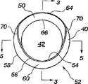
图2示出从开口42侧观察到的皮托管入口40的视图。入口40的开口42是由一个外周边缘54环绕成的,该边缘构成了入口40的开口42。开口42的外周边缘54的第一部分56从入口40的圆周壁58向内设置从而形成了一个倾斜的肩部60。倾斜的肩部60与转子14的内圆周表面36间隔开一距离。然而,倾斜的肩部60设置成可接触转子内的高速流体,尤其是,可将其设计成有助于流体流入到开口42中,而且使不能流入到开口42中的流体向远离入口40方向偏转从而减小对入口40的损害。倾斜的肩部60的特定角度和/或曲率可以进行改变以便满足特定流体应用的需要。FIG. 2 shows a view of
开口42的外周边缘54的第二部分64从开口的中心向外延伸,以便向外扩张或者从开口42及外周边缘54的底部56向外延伸从而提供了一个唇部50。将唇部50设置在泵内并位于转子14的内圆周表面36的附近位置上。外周边缘54的第二部分64接触积聚在转子14的内圆周表面36上的固体,而且唇部50将有效地挖出这些已经积聚的固体。A
唇部50还包括一个内倾斜表面66,将该表面设计成可将除去的或者俘获的固体导入到入口40的开口42内,这些固体从开口42经皮托管组件排出。内倾斜表面66具有一弯曲部分,其不仅易于将固体导入到开口42中,而且易于使固体和液体以减小通常对皮托管入口的损害作用的方式来偏转。结果,皮托管入口40(及插入件52)的使用寿命增加了。
在外周边缘54的向内设置的第一部分56过渡到外周边缘54的向外设置的第二部分64之处设有一个外周边缘54的过渡区域70。在图5的横截面视图中,进一步示出了外周边缘54的过渡区域70,与入口40的倾斜肩部60相比,入口40的圆周壁58弯曲较小,从而提供了一个过渡肩部74,而且入口40的内表面76还朝外周边缘54向外弯曲从而提供了一个过渡的内倾斜表面78。包含本发明第一实施例的结构元件还可在图6和7中计算机生成的三维模型中示出。A
此外,如图2-7所示,图示的本发明皮托管入口40为一个可以连接到皮托管臂上的插入件52,该皮托管臂已经浇铸和/或机加工出一个开口来容纳该插入件52。为了能将该插入件52容纳在皮托管臂中,插入件52还设有一个颈部80,该颈部80的外径82(图3和图5)小于入口40的圆周壁58的外径84。台阶86抵靠在一个环绕着在皮托管臂内形成的浇铸或者机加工的开口的边缘上。Additionally, as shown in FIGS. 2-7, the
入口40的唇部50设计成不仅能挖出积聚在转子的内圆周表面上的固体,而且还能将自由移动的固体引导到入口40的开口42中以便同时将这些固体除去。此外,入口40的倾斜肩部60设计成可提供一种供流体在其上流动的空气动力表面,从而提高泵的效率。尽管入口40的唇部50,借助于其向外扩张的结构以及内倾斜表面66,对流体和固体在转子内圆周面上的运动产生了某些阻碍从而减少了泵的效率,但是已经证明,由于该阻碍作用引起的泵效率的损失可以通过解决积聚的固体问题来获得皮托管效率增加和使用寿命提高。The
如图1-7所示,本发明的第一个实施例示出了一种具有唇部50的入口40,其中,唇部50绕由外周边缘54形成的开口42的圆周延伸约180°。但,如图8的一种变型实施例所示,唇部50可以绕入口40的开口42延伸约360°从而提供一种相对开口42的整个圆周的挖掘能力。图8是经变型实施例的入口40的横截面视图,而且该视图与沿入口40的纵轴线90剖开的横截面位置无关,都是相同的。As shown in FIGS. 1-7 , a first embodiment of the present invention shows an
皮托管入口40的唇部50尤其是由于设置了内倾斜表面66,将会更有效地将固体和流体导入到入口40的开口42中并且铲除积聚在转子的外周边缘上的固体。但,唇部50的360°延伸范围增加了流体的阻力并可能因而降低效率。在使用高固体含量的液体中,具有360°唇部50的皮托管入口40与现有的不带有唇部的皮托管入口相比仍然具有显著的优点并提高了泵的效率。本发明入口40的唇部50可相对入口40的开口42从5°到360°之间延伸。The
本发明已经描述和示出的入口40是由外周边缘54形成的具有大体上圆形开口42且是由圆周壁58形成的大体上圆形外圆周。然而,入口40及其开口42的形状和尺寸不一定是圆形的。事实上,入口40和/或开口42可以是适于使用的任何合适的形状。作为例子,入口40和开口42可以是卵圆形的形状。The
本发明的入口40可以利用现有的方法在一个模具中通过浇铸制成,入口40可以是作为皮托管臂的一部分来一体制成或者以插入件的型式来制成。可替换的是,尤其是针对本发明包含360°唇部的实施例而言,入口40可以利用现有技术中已知的方法对棒料进行机加工制成。入口可以由诸如碳化钨的具有较高抗腐蚀性的任何合适的材料来制成。各种其它的材料同样都可使用。The
将皮托管入口设计成当输送含有固体的流体,尤其是当固体具有沿泵的转子的内圆周表面积聚的一种型式或者集结物时,能提供较高的泵效率。本发明的皮托管入口可在形状和尺寸上进行修改以便满足各种应用的需要。因此,本文针对本发明的结构和功能的详细描述仅供参考性而非限定性的。Pitot tube inlets are designed to provide higher pump efficiency when conveying fluids containing solids, especially when the solids have a pattern or buildup that accumulates along the inner circumferential surface of the pump's rotor. The pitot tube inlet of the present invention can be modified in shape and size to meet the needs of various applications. Therefore, the detailed description of the structure and function of the present invention herein is only for reference and not for limitation.
Claims (11)
Applications Claiming Priority (2)
| Application Number | Priority Date | Filing Date | Title |
|---|---|---|---|
| US31819601P | 2001-09-07 | 2001-09-07 | |
| US60/318,196 | 2001-09-07 |
Publications (2)
| Publication Number | Publication Date |
|---|---|
| CN1551951A true CN1551951A (en) | 2004-12-01 |
| CN1270094C CN1270094C (en) | 2006-08-16 |
Family
ID=23237085
Family Applications (1)
| Application Number | Title | Priority Date | Filing Date |
|---|---|---|---|
| CNB028173805A Expired - Fee Related CN1270094C (en) | 2001-09-07 | 2002-09-06 | Improved pitot tube insert |
Country Status (4)
| Country | Link |
|---|---|
| US (1) | US6709227B2 (en) |
| EP (1) | EP1423612A4 (en) |
| CN (1) | CN1270094C (en) |
| WO (1) | WO2003023230A1 (en) |
Cited By (2)
| Publication number | Priority date | Publication date | Assignee | Title |
|---|---|---|---|---|
| CN102182705B (en) * | 2008-12-30 | 2013-03-06 | 王梦川 | High-efficiency rotary shell pump |
| CN107842507A (en) * | 2013-03-15 | 2018-03-27 | 环境技术泵系统股份有限公司 | Gear drive flow type pitot tube pump |
Families Citing this family (3)
| Publication number | Priority date | Publication date | Assignee | Title |
|---|---|---|---|---|
| GB201417859D0 (en) * | 2014-10-09 | 2014-11-26 | Rolls Royce Plc | A coupling and a method of using the same |
| CN108138782B (en) * | 2015-09-14 | 2021-01-29 | 特种泵和系统有限责任公司 | Pitot tube stabilizing device |
| US12313087B2 (en) * | 2019-12-06 | 2025-05-27 | Kinetic Technology Systems, Llc | Energy-conserving fluid pump |
Family Cites Families (18)
| Publication number | Priority date | Publication date | Assignee | Title |
|---|---|---|---|---|
| US3093080A (en) | 1961-03-15 | 1963-06-11 | Tarifa Carlos Sauchez | Hydraulic pumps |
| US3374747A (en) | 1966-08-19 | 1968-03-26 | Loyal W James | Self-priming device and method for pumps |
| US3384023A (en) * | 1966-09-19 | 1968-05-21 | Loyal W James | Pump and method of pumping |
| US3776658A (en) | 1972-08-14 | 1973-12-04 | Kobe Inc | Pitot tube for pitot pump |
| US3822102A (en) | 1973-03-05 | 1974-07-02 | Kobe Inc | Pitot pump with thrust balance |
| US3999881A (en) | 1975-09-02 | 1976-12-28 | Kobe, Inc. | Centrifugal pump of the pitot type |
| US4183713A (en) | 1975-11-17 | 1980-01-15 | Kobe, Inc. | Pitot pump with jet pump operated thrust balance |
| US4264269A (en) * | 1978-09-25 | 1981-04-28 | Kobe, Inc. | Centrifugal pitot pump with improved pitot |
| US4279571A (en) | 1979-10-01 | 1981-07-21 | Kobe, Inc. | Pitot pump with fluid lubricated bearings |
| US4267964A (en) * | 1979-10-01 | 1981-05-19 | Kobe, Inc. | Centrifugal separator with rotating pick-up tube |
| US4252499A (en) | 1979-10-01 | 1981-02-24 | Kobe, Inc. | Centrifugal pump |
| SU901633A1 (en) | 1980-02-11 | 1982-01-30 | Предприятие П/Я М-5356 | Bucket pump |
| US4674950A (en) | 1985-11-12 | 1987-06-23 | Dresser Industries, Inc. | Pitot tube for pitot type centrifugal pump |
| SU1399507A2 (en) | 1986-06-10 | 1988-05-30 | Предприятие П/Я М-5356 | Scoop pump |
| US4784630A (en) * | 1986-12-17 | 1988-11-15 | Fuji Jukogyo Kabushiki Kaisha | Rotating speed detecting device for a continuously variable transmission for a vehicle |
| SU1513205A1 (en) | 1987-12-30 | 1989-10-07 | Предприятие П/Я М-5356 | Scoop diffuser of pump |
| US5385446A (en) | 1992-05-05 | 1995-01-31 | Hays; Lance G. | Hybrid two-phase turbine |
| US5997243A (en) * | 1998-01-21 | 1999-12-07 | Envirotech Pumpsystems, Inc. | Pitot tube inlet insert |
-
2002
- 2002-09-06 EP EP02798141A patent/EP1423612A4/en not_active Withdrawn
- 2002-09-06 CN CNB028173805A patent/CN1270094C/en not_active Expired - Fee Related
- 2002-09-06 WO PCT/US2002/028356 patent/WO2003023230A1/en not_active Ceased
- 2002-09-06 US US10/236,197 patent/US6709227B2/en not_active Expired - Fee Related
Cited By (2)
| Publication number | Priority date | Publication date | Assignee | Title |
|---|---|---|---|---|
| CN102182705B (en) * | 2008-12-30 | 2013-03-06 | 王梦川 | High-efficiency rotary shell pump |
| CN107842507A (en) * | 2013-03-15 | 2018-03-27 | 环境技术泵系统股份有限公司 | Gear drive flow type pitot tube pump |
Also Published As
| Publication number | Publication date |
|---|---|
| US6709227B2 (en) | 2004-03-23 |
| EP1423612A4 (en) | 2009-05-27 |
| WO2003023230A1 (en) | 2003-03-20 |
| US20030077165A1 (en) | 2003-04-24 |
| EP1423612A1 (en) | 2004-06-02 |
| CN1270094C (en) | 2006-08-16 |
Similar Documents
| Publication | Publication Date | Title |
|---|---|---|
| JP2006527804A (en) | Improved pump impeller | |
| EP2428684A1 (en) | Impeller for centrifugal compressor | |
| CN1270094C (en) | Improved pitot tube insert | |
| KR102381264B1 (en) | A pump that minimizes the jamming of foreign substances by the anti-jamming ring | |
| CN1131978A (en) | low wear turbine | |
| CN110192038A (en) | The impeller with rotor blade for centrifugal pump | |
| US5785495A (en) | Fiber-repellant centrifugal pump | |
| CN101371047A (en) | Flexible floating ring seals for rotodynamic pumps | |
| HU217252B (en) | Centrifugal slurry pump | |
| US20090232639A1 (en) | Wear plate for a centrifugal pump | |
| JP7724097B2 (en) | Pump casing and pump | |
| US7470106B1 (en) | Centrifugal slurry pump | |
| AU738519B2 (en) | Pitot tube inlet insert | |
| EA026576B1 (en) | Improvements to pumps and components therefor | |
| US11236763B2 (en) | Inverted annular side gap arrangement for a centrifugal pump | |
| JP2004501317A (en) | Fuel pump with low influence of pollutants | |
| CN114667396A (en) | Separating device and fluid machine with a separating device | |
| US20090269201A1 (en) | Air diffuser system for industrial pumps | |
| US11511335B2 (en) | Gas suction device of casting mold | |
| JP4106214B2 (en) | Pump device | |
| KR101203241B1 (en) | Centrifugal Blower | |
| CN1517560A (en) | Vane of vehicle fuel feed pump | |
| CN111954764A (en) | Pump housing assembly and fluid pump for fluid pumps | |
| CN1165687C (en) | Blade wheel for sand-discharging water pump | |
| JP6861623B2 (en) | Impeller and pump equipped with it |
Legal Events
| Date | Code | Title | Description |
|---|---|---|---|
| C06 | Publication | ||
| PB01 | Publication | ||
| C10 | Entry into substantive examination | ||
| SE01 | Entry into force of request for substantive examination | ||
| C14 | Grant of patent or utility model | ||
| GR01 | Patent grant | ||
| C17 | Cessation of patent right | ||
| CF01 | Termination of patent right due to non-payment of annual fee |
Granted publication date: 20060816 Termination date: 20090906 |