CN1551994A - Method for producing light of a specified polarization state - Google Patents
Method for producing light of a specified polarization state Download PDFInfo
- Publication number
- CN1551994A CN1551994A CNA028134451A CN02813445A CN1551994A CN 1551994 A CN1551994 A CN 1551994A CN A028134451 A CNA028134451 A CN A028134451A CN 02813445 A CN02813445 A CN 02813445A CN 1551994 A CN1551994 A CN 1551994A
- Authority
- CN
- China
- Prior art keywords
- light
- polarization state
- optical splitter
- inlet
- polarization
- Prior art date
- Legal status (The legal status is an assumption and is not a legal conclusion. Google has not performed a legal analysis and makes no representation as to the accuracy of the status listed.)
- Granted
Links
Images


Classifications
-
- G—PHYSICS
- G02—OPTICS
- G02B—OPTICAL ELEMENTS, SYSTEMS OR APPARATUS
- G02B5/00—Optical elements other than lenses
- G02B5/30—Polarising elements
-
- G—PHYSICS
- G02—OPTICS
- G02B—OPTICAL ELEMENTS, SYSTEMS OR APPARATUS
- G02B5/00—Optical elements other than lenses
- G02B5/30—Polarising elements
- G02B5/3025—Polarisers, i.e. arrangements capable of producing a definite output polarisation state from an unpolarised input state
-
- G—PHYSICS
- G02—OPTICS
- G02B—OPTICAL ELEMENTS, SYSTEMS OR APPARATUS
- G02B27/00—Optical systems or apparatus not provided for by any of the groups G02B1/00 - G02B26/00, G02B30/00
- G02B27/28—Optical systems or apparatus not provided for by any of the groups G02B1/00 - G02B26/00, G02B30/00 for polarising
- G02B27/286—Optical systems or apparatus not provided for by any of the groups G02B1/00 - G02B26/00, G02B30/00 for polarising for controlling or changing the state of polarisation, e.g. transforming one polarisation state into another
Landscapes
- Physics & Mathematics (AREA)
- General Physics & Mathematics (AREA)
- Optics & Photonics (AREA)
- Polarising Elements (AREA)
- Projection Apparatus (AREA)
- Optical Communication System (AREA)
- Optical Couplings Of Light Guides (AREA)
- Control Of The Air-Fuel Ratio Of Carburetors (AREA)
- Investigating, Analyzing Materials By Fluorescence Or Luminescence (AREA)
Abstract
产生指定偏振状态光的方法,其中在偏振状态敏感的分光器入口处导入光,将指定偏振状态的光从分光器在第一出口输出。将具有与指定状态有偏差的偏振状态的光相对这种状态进行改变和输出。本发明涉及偏振器装置,照明装置,投影系统及其应用。
A method for generating light with a specified polarization state, wherein light is introduced at the entrance of a beam splitter that is sensitive to the polarization state, and the light with the specified polarization state is output from a first exit of the beam splitter. Light having a polarization state deviating from the specified state is then modified and output relative to this state. This invention relates to polarizer devices, illumination devices, projection systems, and their applications.
Description
本发明涉及用于产生指定偏振状态光的方法,其中在偏振状态敏感的分光器入口处导入光,将指定偏振状态的光从分光器在第一出口输出,将具有与指定状态有偏差的偏振状态的光相对这种状态进行改变和输出。此外本发明涉及偏振器装置,照明装置,投影系统以及它们的应用。The invention relates to a method for producing light of a specified polarization state, wherein the light is introduced at the entrance of a polarization state sensitive beam splitter from which light of the specified polarization state is output at a first exit will have a polarization deviating from the specified state The state of the light is changed and output relative to this state. Furthermore the invention relates to polarizer arrangements, lighting arrangements, projection systems and their use.
从US-A-6 139 157中已知开始叙述类型的一种方法或者按照这种方法工作的照明系统。穿过光隧道以及透镜系统之后将非偏振光输入给偏振状态敏感的分光器。将被输入的非偏振光起振为指定偏振状态的部分在分光器的第一出口输出期间,将具有与指定偏振状态有偏差的非偏振光状态相对这种状态进行改变和在分光器的第二出口输出。Known from US-A-6 139 157 a kind of method of described type or according to the lighting system of this method work. After passing through the light tunnel and lens system, the unpolarized light is input to the polarization state sensitive beam splitter. The portion of the input unpolarized light that is oscillated to a specified polarization state is output at the first exit of the beam splitter, and the state of the unpolarized light that has a deviation from the specified polarization state is changed relative to this state and at the first exit of the beam splitter. Two export output.
这种方法有以下缺点:This approach has the following disadvantages:
因为最后成为指定状态的偏振光在分光器的两个分离区域或者出口输出,设计了用于精确接受来自两个区域光的紧相连的照明光学部件,这使得整个系统没有灵活性而且体积很大。Because the polarized light that finally becomes the specified state is output at two separate regions or exits of the beam splitter, closely connected illumination optics are designed to precisely receive light from the two regions, which makes the whole system inflexible and bulky .
本发明的任务是建立一种方法和一种按照这种方法工作的偏振器装置,这种装置避免了上述缺点。The object of the present invention is to create a method and a polarizer arrangement operating according to this method, which avoid the above-mentioned disadvantages.
这项任务按开始叙述的方法是这样解决的,将改变偏振状态的光重新导入偏振敏感分光器的入口。This task is solved in the manner described at the outset in that the light with changed polarization state is reintroduced into the inlet of the polarization-sensitive beam splitter.
因此实际上整个非偏振光最后达到了以所希望偏振状态从分光器中输出。这是因为将光一直在第二出口输出并被偏转直到具有至少接近指定的偏振状态,然后同样在第一出口离开分光器。Thus virtually the entire unpolarized light finally reaches the output of the beam splitter in the desired polarization state. This is because the light is output all the way at the second exit and is deflected until it has at least close to the specified polarization state, before leaving the beam splitter also at the first exit.
如还要叙述的,按照本发明方法优异的实施形式揭示了具有最大优越性的实现方法,即通过反射,优选通过多次反射将光的偏振状态改变。As will be stated further, an advantageous embodiment of the method according to the invention reveals the most advantageous implementation method, namely the change of the polarization state of the light by reflection, preferably by multiple reflection.
在另外一个优异的实施形式中,特别优选与上述反射状态改变结合,通过预先规定的延迟,优选借助于至少一个延迟器元件,将光的偏振状态改变。In a further advantageous embodiment, particularly preferably in conjunction with the aforementioned change in the reflection state, the polarization state of the light is changed by means of a predetermined delay, preferably by means of at least one retarder element.
从US 6 139 157中已知,进入分光器的光首先从一个光源用反射器聚焦在光隧道的孔上和通过光隧道周边内表面的多次反射作用使光强度分布在其输出侧均匀化。因此也已知,为了强度均匀化的原因,对于非偏振的、输入分配光的光应安排一个具有多次反射的光程。It is known from US 6 139 157 that the light entering the beam splitter is first focused from a light source on the aperture of the light tunnel with a reflector and the light intensity distribution is homogenized on its output side by multiple reflections from the inner surface of the light tunnel periphery . It is therefore also known that, for reasons of intensity homogenization, an optical path with multiple reflections should be arranged for unpolarized light entering the distribution light.
于是在按照本发明方法最优越的实施形式中,在将光导入偏振状态敏感的分光器之前同样将光引导通过一具有反射周边的光隧道组件,并且将具有与指定偏振状态垂直的状态的光从与照明光源相反的一端进入光隧道组件,并且在其上进行反射。因此该由于强度均匀化原因为非偏振光安排的光隧道组件同时被充分利用,以便将非偏振光的不在指定状态的偏振光部分相对其偏振状态进行改变和重新输入到分光器的入口。因此实现了最紧凑和最简单的按照本发明的实施。In the most advantageous embodiment of the method according to the invention, before the light is introduced into the polarization state-sensitive beam splitter, the light is also guided through a light tunnel element with a reflective periphery and the light having a state perpendicular to the specified polarization state Enter the light tunnel assembly from the end opposite to the illumination source and reflect on it. The light tunnel assembly arranged for unpolarized light for reasons of intensity homogenization is thus simultaneously fully utilized in order to change and reintroduce the polarized part of the unpolarized light not in the specified state relative to its polarization state to the entrance of the beam splitter. The most compact and simplest implementation according to the invention is thus achieved.
优选在至少一个引入光的区域在组件中安排至少一个起指定的,定义的改变偏振状态作用的元件,优选至少一个延迟器片。Preferably at least one element, preferably at least one retarder plate, is arranged in the assembly in at least one region where light is introduced, which acts to change the polarization state in a specific, defined manner.
在另一优异实施形式中,借助于一个光源和一个反射器产生导入分光器入口的光和将与指定偏振状态垂直状态光的至少一部分至少还在反射器上反射和将在那里被反射的光输入到偏振状态敏感的分光器上。In a further advantageous embodiment, the light which is directed at the entrance of the beam splitter and which is to be at least part of the light perpendicular to the specified polarization state is also reflected at least on the reflector and is to be reflected there by means of a light source and a reflector Input to a polarization state sensitive beamsplitter.
该后面叙述的过程特别适合于与已经叙述过的光隧道组件设置组合在一起,借助用上述反射器实际上建立了对光隧道组件窗孔的封闭空间,这样无论如何使得从分光器第二出口和通过光隧道窗孔出来的那部分光不会丢失,而是通过反射器重新反射到光隧道组件中。其中优选反射器的形状类似于一个乌尔伯利特球(Ulbricht’sche Kugel)。This latter narrated process is particularly suitable for being combined with the already described light tunnel assembly setting, by means of using the above-mentioned reflector to actually establish a closed space for the light tunnel assembly aperture, so that in any case from the second exit of the beam splitter And the part of the light that comes out through the light tunnel window is not lost, but is re-reflected into the light tunnel assembly by the reflector. Wherein it is preferred that the shape of the reflector resembles an Ulbricht'sche Kugel.
在最后叙述过程的另一优异实施形式中也在反射器面上安排了一个起指定偏振状态改变作用的元件。In a further advantageous embodiment of the last-mentioned process, an element is also arranged on the reflector surface which acts to change the specified polarization state.
在权利要求8详细叙述了按照本发明的偏振装置及其按照权利要求9至16的优异实施形式。在权利要求17中详细叙述了按照本发明的照明装置,按照本发明的投影系统详细叙述在权利要求19中。按照本发明的装置以及按照本发明的方法非常好地适于应用在投影仪或者照明装置领域内。Claim 8 specifies the polarizer according to the invention and advantageous embodiments thereof according to
随后借助附图举例叙述本发明。这些附图是:The invention is subsequently described by way of example with the aid of the figures. These drawings are:
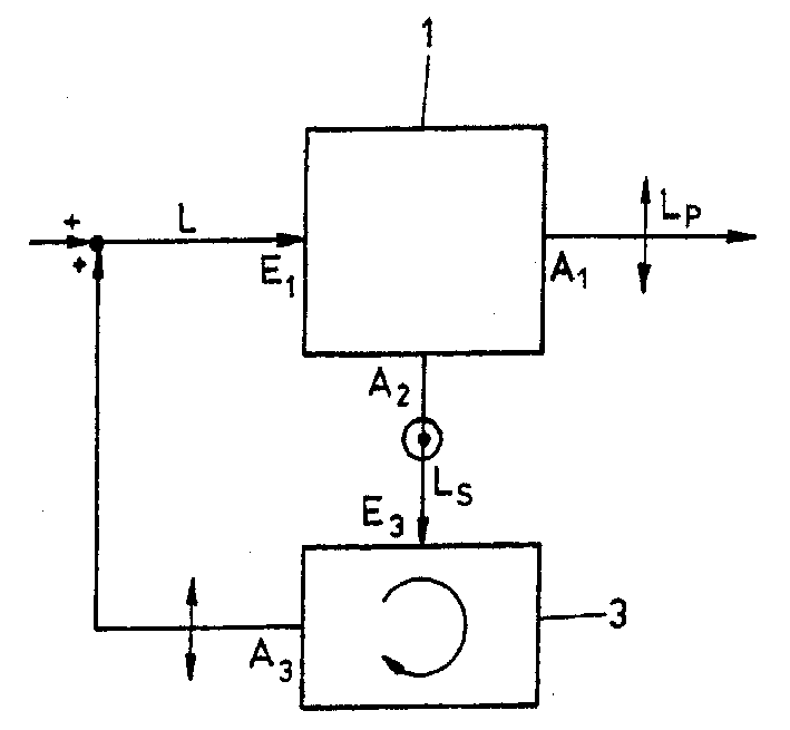
图1借助于一个光学的功能块/信号流程图表示了按照本发明方法的原理,本发明的偏振装置按照这个原理工作;Fig. 1 has represented the principle according to the method of the present invention by means of an optical functional block/signal flow chart, and the polarization device of the present invention works according to this principle;
图2与图1相似的图中表示了偏振旋转或者偏振改变的组件的优选构成;Figure 2 is a view similar to Figure 1 showing a preferred configuration of a polarization rotation or polarization changing assembly;
图3在类似于图1和2的图中表示了按照本发明的方法或者按照本发明的装置优异的实施形式,在其中同样的部件不仅充分利用在光强度分布均匀化而且充分利用在按照本发明的偏振状态旋转或者偏振状态改变上;FIG. 3 shows in a diagram similar to FIGS. 1 and 2 a preferred embodiment of the method according to the invention or of the device according to the invention, in which the same components are fully utilized not only for the homogenization of the light intensity distribution but also for the homogenization of the light intensity distribution according to the invention. Inventive polarization state rotation or polarization state change;
图4借助于图3所表示的过程优异实施形式;Fig. 4 is by means of the excellent implementation form of the process represented in Fig. 3;
图5安排了偏振状态敏感的分光器的第一个优异实施形式;Fig. 5 arranges the first excellent embodiment of the polarization state-sensitive beam splitter;
图6安排了偏振状态敏感的分光器的另一个优异实施形式;Fig. 6 arranges another excellent implementation form of the polarization state-sensitive beam splitter;
图7在另一优异实施形式中简化表示了使用按照本发明的方法或者按照本发明的偏振装置或者按照本发明的投影装置。FIG. 7 shows a simplified representation of the use of the method according to the invention or the polarization device according to the invention or the projection device according to the invention in a further advantageous embodiment.
借助于图1应该首先使用一个光学功能块/信号流程图叙述本发明的基本原理。一般来说将从投影仪光源出来的非偏振光线L传送到偏振状态敏感的分光器1上。偏振方向敏感的分光器1在它的光出口A1将非偏振光线L中有指定偏振状态例如P-偏振的部分LP输出。将非偏振光L的一部分LS,这个与在A1传出的光偏振状态P有一个垂直的、根据这个例子即S-偏振状态,将其从偏振状态敏感的分光器1的第二光学出口A2输出。一般来说将上述光L的一部分即Lp,通过偏振滤波器层系统在偏振状态敏感的分光器1上透射,将其余的例如Ls在这里反射。With the aid of FIG. 1, the basic principle of the invention should first be described using an optical functional block/signal flow diagram. Generally, the unpolarized light L from the light source of the projector is passed to the polarization state sensitive beam splitter 1 . The polarization-sensitive beam splitter 1 outputs at its light outlet A1 the part L P of the unpolarized light L having a specified polarization state, eg P-polarization. Take a part L S of the unpolarized light L, which has a perpendicular, according to this example, S-polarization state to the outgoing light polarization state P at A 1 , and pass it from the second optical Exit A 2 output. Generally, a part of the above-mentioned light L, L p , is transmitted via the polarization filter layer system at the polarization-state-sensitive beam splitter 1 , and the remainder, for example L s , is reflected there.
具有所希望的偏振状态的光Lp在光出口A1出来。将偏振状态敏感的分光器1出口A2出来的光Ls在偏振状态旋转或者改变的元件3上将其偏振状态改变或者旋转并且重新传送到偏振状态敏感的分光器1的光入口E1上。因此实际上整个传送给分光器1的起初非偏振的光L最后是作为具有所希望的偏振状态例如P的Lp输出。Light Lp with the desired polarization state emerges at light outlet A1 . The light L s coming out of the polarization state-sensitive beam splitter 1 exit A 2 has its polarization state changed or rotated on the polarization state rotating or changing element 3 and is retransmitted to the polarization state-sensitive beam splitter 1 light inlet E 1 . Thus virtually the entire initially unpolarized light L delivered to the beam splitter 1 is finally output as Lp with the desired polarization state, eg P.
如图2表示了如果按照图1在光出口A2出来的光Ls经过多次反射,就可以优异实现偏振状态旋转的元件3。一般来说通过反射不再保持光的偏振状态。如果光Ls的偏振状态也只有很少的旋转,于是的确还会有一部分P偏振化而且在出口A1作为LP部分输出来。其余部分可能需要经过装置3的多次循环直到其偏振方向相当于所要求的P-偏振。Figure 2 shows that if the light L s coming out of the light outlet A2 according to Figure 1 is reflected multiple times, the polarization state rotation can be excellently realized. Generally the polarization state of the light is no longer maintained by reflection. If the polarization state of the light L s is also rotated only slightly, then indeed a portion of the P polarization is also output at the exit A 1 as the L P portion. The remainder may require multiple cycles through the device 3 until its polarization direction corresponds to the desired P-polarization.
如图2表示的在装置3上可以优异地通过安排附加分立的偏振方向旋转元件,特别是所谓的“延迟器”元件加强偏振状态的旋转,首先根据附图1的原理借助这些元件将引入光Ls的λ/2延迟,也就是说偏振方向旋转90°。As shown in Figure 2, the rotation of the polarization state can be enhanced excellently by arranging additional discrete polarization rotation elements, in particular so-called "retarder" elements, on the device 3, first according to the principle of the accompanying drawing 1 by means of which the incoming light λ/2 retardation of L s , that is to say the polarization direction is rotated by 90°.
在图2方框3上一方面示意地表示了用于光LS的多次反射装置6。另一方面用虚线表示了装入的、附加的分立偏振方向旋转元件,例如是一个延迟器片8。On the one hand, block 3 in FIG. 2 schematically shows a multiple reflection device 6 for light L S . On the other hand, an incorporated, additional discrete polarization direction rotating element, for example a retarder plate 8, is indicated by dashed lines.
如在引言中叙述过的,在很多应用特别是在投影仪中通常希望提供强度尽可能均匀分布的光束。为此也如开始已经叙述过的已知,首先将来源于光源的非常小区域的一束光传送到光隧道,在其中通过来源于光源的光多次反射,在输出侧提供一个均匀的、一般来说与形成图形的元件形状相匹配的强度分布。As stated in the introduction, in many applications, especially in projectors, it is often desirable to provide a light beam with an intensity distribution as uniform as possible. For this purpose, as already stated at the outset, it is known that first a beam of light originating from a very small area of the light source is conveyed into a light tunnel, in which a homogeneous, An intensity distribution that generally matches the shape of the element forming the pattern.
但是如果现在在偏振状态敏感的分光器1的入口侧,如图3示意表示,安排了由于均匀化原因将输入光L多次反射的组件,此被安排的多次反射组件与图1和2的元件3类似优异地同时使用作为偏振方向旋转组件。But if now on the entrance side of the beam splitter 1 sensitive to the polarization state, as shown schematically in FIG. Element 3 is similarly excellent for both use as a polarization rotation component.
按照图3光Le射在多次反射的组件3a上,如已经叙述过作为举例优异地射在光隧道的光入口E3a上,并且在多次反射之后强度均匀化地传送给偏振状态敏感的分光器1的入口E1上。According to FIG. 3 the light L e impinges on the multiple-reflecting
现在在与光入口E1相同的光出口A2上将不希望的偏振状态光LS传回到多次反射元件3a的出口A3a上,在那里经过多次反射之后被反射回来,并且作为具有现在已经旋转了偏振方向的光L的一部分,又传送到偏振敏感的分光器1上。用这种方式和方法充分利用了已经由于强度均匀化原因安排的多次反射组件3a,其中如下面还要叙述的,又可以安排专门的、分立的偏振旋转元件如延迟器片,并且实现按照本发明如图1或者图2中的方块3叙述过的应安排的偏振状态旋转。Now on the same light exit A2 as the light entrance E1 , the undesired polarization state light L S is passed back to the exit A 3a of the
在图4中表示了借助图3叙述的优异实施原理优异的实施形式。例如来自投影光源的光Le通过光隧道3a出口E3a的窗口7进入,并且只要与光隧道光轴A不是近似平行,则在光隧道3a高反射的内壁9上被一次或多次地反射。An excellent embodiment of the excellent embodiment principle described with reference to FIG. 3 is shown in FIG. 4 . For example, the light Le from the projection light source enters through the
将射入的光线或者例如其光路用虚线画在附图4上。The incident light rays or, for example, their beam paths are shown in dotted lines on FIG. 4 .
优选直接在光隧道3a的出口A3a处安排偏振状态敏感的分光器1a,所希望的偏振状态光LP并且具有均匀的分布强度从光出口A1a输出。The polarization state-
用图3的叙述,将用线画在图4上与所希望的偏振状态,这里是P,有偏差的光隧道3a中的光LS返回到光隧道3a中,在那里经过多次反射之后最后反射在围绕窗口7构成内部反射的光隧道端壁11上,将首先通过多次反射被旋转的偏振状态又在光隧道出口A3a处传送给偏振状态敏感的分光器1a上。借此经过这样的旋转之后在所希望方向上或者在所希望状态上的偏振的光作为光LP的一部分从分光器1a输出。其中将端壁11的反射内壁调整得与反射平面或者与分光器1a的平均位置E′(见图5)相平行。With the description of Fig. 3, the light L S in the
在实现按照图4优异实施例中在入口窗口7和光隧道3a的出口A3a或偏振状态敏感的分光器1a入口之间安排了起分立的指定偏振状态旋转作用的一个或多个光学元件。如图4用虚线表示的,在光隧道3a横截面上可以安排用13a表示的偏振状态旋转元件,例如优选λ/4-延迟器片,和/或在光隧道3a周围壁上如在13b表示的和/或在光隧道3a定义的入口窗口7的入口侧的端壁11上如在图4上用13c表示的。同样优异的是安排这种偏振状态旋转元件,特别是λ/4-延迟器片,在围绕入口窗口7端壁11用13c表示的。由于光LS两次穿过λ/4-延迟器片的路段因此得到了90°的偏振状态旋转。Between the
如图4已经表示的,优越的是使用片状的偏振状态敏感的分光器1a。此时必须根据出现的光强度来决定,是否可以使用以塑料为基础的偏振分光器,或者使用在玻璃基体上用胆甾醇型滤波器的分光器。As already shown in FIG. 4, it is advantageous to use a plate-shaped polarization state-
但是还可以使用一种在三层涂层的玻璃棱镜基础上实现的如图5表示的偏振分光器1b。However, it is also possible to use a polarizing beam splitter 1b as shown in FIG. 5 realized on the basis of triple-coated glass prisms.
如果射入分光器1b的光L和LS期望尽可能小的平行偏移Δ,优选如同图6表示的,现在被称为1c的偏振状态选择性分光器以三棱镜结构I,II...陈列实现。结构越细,上述平行偏移Δ越小。If the light L and L S entering the beam splitter 1b are expected to have a parallel deviation Δ as small as possible, preferably as shown in Figure 6, the polarization state selective beam splitter now called 1c has a prism structure I, II... The display is realized. The finer the structure, the smaller the above-mentioned parallel offset Δ.
在图4上还可以看到,光LS在反射之后没有射在围绕入口窗口7的终端11上,而是穿过入口窗口7离开光隧道而丢失了。在图7,在按照本发明的投影仪的例子范围内,表示了这个问题的解决方法。光源17的光在聚焦的反射器15的入口窗口7上是这样形成的,偏振状态敏感的分光器1a或者1b或者1c的光不能从系统中丢失,并且还在光隧道3a的反射器15上反射。此时可以将反射器15设计为主要是相当于乌尔伯利特球的形状。It can also be seen in FIG. 4 that after reflection the light LS does not strike the terminal 11 surrounding the
专门按照本发明的投影仪除了已经叙述过的元件之外还包括一个彩色快门19以及一个透镜系统21,此外还有分光器23,由于已经按照本发明安排的偏振状态选择性的分光器1a不是强制性地必须将这个构成为偏振状态敏感的分光器。最后将27称为投影透镜。The projector in particular according to the invention comprises, in addition to the elements already described, a color shutter 19 and a lens system 21, and also a beam splitter 23, since the polarization state-
此外如图7表示和叙述的,还可以在反射器15上安排一个分立的偏振方向旋转元件,在图7上被称为13d。Furthermore, as shown and described in FIG. 7, it is also possible to arrange on the reflector 15 a separate polarization direction rotating element, referred to in FIG. 7 as 13d.
用图7优选安排的颜色快门,例如具有三种选择颜色的透射区(没有示出)例如选择性透射的红,绿和蓝,进行光线LP的彩色调制。优选将彩色快门19构成为彩色轮。优选安排了以反射工作的光阀阵列作为形成图像的元件25,在其上按像素地和在安排彩色快门19时与最后的时间同步,在被投影的图像上控制各个像素的强度。Color modulation of the light LP is performed with the color shutter preferably arranged in Fig . 7, for example with transmissive regions (not shown) of three selected colors such as selectively transmissive red, green and blue. The color shutter 19 is preferably designed as a color wheel. A reflection-operating light valve array is preferably arranged as image forming element 25 on which the intensity of the individual pixels in the projected image is controlled pixel by pixel and synchronized with the last time when the color shutter 19 is arranged.
偏振状态敏感的分光器可以是一个元件,它使波长范围为Δλ1的光在第一偏振状态透射和在与之垂直的第二偏振状态反射,而另一波长范围Δλ2的光在第二偏振状态透射和在第一个偏振状态反射。A polarization-sensitive beamsplitter may be an element that transmits light in a wavelength range Δλ 1 in a first polarization state and reflects in a second polarization state perpendicular thereto, while light in another wavelength range Δλ 2 is transmitted in a second polarization state. The polarization state is transmitted and reflected in the first polarization state.
于是从分光器中出来的光具有依赖于波长范围的偏振状态。这种依赖于波长范围的偏振分布常常在投影仪上特别是在以反射的LCD′s为基础的投影仪上是需要的。偏振状态敏感的元件可以由延迟器堆垛和后置的偏振分光器构成,共同起作用成为波长选择的、偏振状态敏感的分光器。The light emerging from the beam splitter then has a polarization state which is dependent on the wavelength range. Such wavelength-range-dependent polarization distributions are often required in projectors, especially projectors based on reflective LCD's. The polarization state-sensitive element can be composed of a retarder stack and a post-polarization beam splitter, which together function as a wavelength-selective, polarization-state-sensitive beam splitter.
Claims (20)
Applications Claiming Priority (3)
| Application Number | Priority Date | Filing Date | Title |
|---|---|---|---|
| CH1236/01 | 2001-07-04 | ||
| CH12362001 | 2001-07-04 | ||
| CH1236/2001 | 2001-07-04 |
Publications (2)
| Publication Number | Publication Date |
|---|---|
| CN1551994A true CN1551994A (en) | 2004-12-01 |
| CN100510804C CN100510804C (en) | 2009-07-08 |
Family
ID=4564426
Family Applications (1)
| Application Number | Title | Priority Date | Filing Date |
|---|---|---|---|
| CNB028134451A Expired - Fee Related CN100510804C (en) | 2001-07-04 | 2002-06-25 | Method for producing light of a given polarisation state, polarizer device and application thereof |
Country Status (10)
| Country | Link |
|---|---|
| US (1) | US7070280B2 (en) |
| EP (1) | EP1402291B1 (en) |
| JP (1) | JP4625634B2 (en) |
| KR (1) | KR100901220B1 (en) |
| CN (1) | CN100510804C (en) |
| AT (1) | ATE311613T1 (en) |
| DE (1) | DE50205127D1 (en) |
| NO (1) | NO20035804L (en) |
| TW (1) | TW589510B (en) |
| WO (1) | WO2003019246A1 (en) |
Families Citing this family (19)
| Publication number | Priority date | Publication date | Assignee | Title |
|---|---|---|---|---|
| US6795243B1 (en) * | 2001-10-05 | 2004-09-21 | Optical Coating Laboratory, Inc. | Polarizing light pipe |
| JP2003202523A (en) * | 2001-11-02 | 2003-07-18 | Nec Viewtechnology Ltd | Polarization unit, polarization illumination device and projection type display device using the illumination device |
| US20050002169A1 (en) * | 2001-11-27 | 2005-01-06 | Valter Drazic | Polarization recycler |
| EP1315022A1 (en) * | 2001-11-27 | 2003-05-28 | Thomson Licensing, Inc. | Polarization recycler |
| US20050134825A1 (en) * | 2002-02-08 | 2005-06-23 | Carl Zeiss Smt Ag | Polarization-optimized illumination system |
| WO2003075083A1 (en) * | 2002-03-06 | 2003-09-12 | Koninklijke Philips Electronics N.V. | Projection device having an increased efficiency |
| US6927910B2 (en) * | 2002-04-19 | 2005-08-09 | Lg Electronics Inc. | Integrator, polarization conversion device, and display apparatus using the same |
| EP1391776A1 (en) * | 2002-07-19 | 2004-02-25 | Sony International (Europe) GmbH | Light collecting, integrating and redirecting device |
| JP3975948B2 (en) * | 2003-03-10 | 2007-09-12 | セイコーエプソン株式会社 | Illumination device and projection device |
| US7379651B2 (en) * | 2003-06-10 | 2008-05-27 | Abu-Ageel Nayef M | Method and apparatus for reducing laser speckle |
| JP4100276B2 (en) * | 2003-07-04 | 2008-06-11 | セイコーエプソン株式会社 | Lighting device and projector |
| EP1714180A1 (en) * | 2004-01-30 | 2006-10-25 | Koninklijke Philips Electronics N.V. | Light-valve projection systems with light recycling |
| JP4144532B2 (en) * | 2004-02-23 | 2008-09-03 | セイコーエプソン株式会社 | Illumination device and projection display device |
| TW200622326A (en) * | 2004-09-15 | 2006-07-01 | Nippon Sheet Glass Co Ltd | Bar-shaped light guide, illumination unit and image-scannig device |
| WO2006043202A1 (en) * | 2004-10-19 | 2006-04-27 | Koninklijke Philips Electronics N.V. | Illumination system |
| US20060232750A1 (en) * | 2005-04-14 | 2006-10-19 | Sanyo Electric Co., Ltd. | Optical member and illuminating device |
| US7434946B2 (en) * | 2005-06-17 | 2008-10-14 | Texas Instruments Incorporated | Illumination system with integrated heat dissipation device for use in display systems employing spatial light modulators |
| GB201108000D0 (en) * | 2011-05-13 | 2011-06-29 | Barco Nv | Polarization preserving dlp optical architecture |
| DE102013204442A1 (en) | 2013-03-14 | 2014-10-02 | Carl Zeiss Smt Gmbh | Optical waveguide for guiding illumination light |
Family Cites Families (20)
| Publication number | Priority date | Publication date | Assignee | Title |
|---|---|---|---|---|
| US4525413A (en) | 1981-03-02 | 1985-06-25 | Polaroid Corporation | Optical device including birefringent polymer |
| JPS63168626A (en) * | 1987-01-06 | 1988-07-12 | Citizen Watch Co Ltd | Liquid crystal display body |
| SG50550A1 (en) * | 1989-07-10 | 2002-04-16 | Rolic Ag | Polarisator |
| JPH04127120A (en) * | 1990-09-18 | 1992-04-28 | Mitsubishi Electric Corp | Projection type display device |
| KR100366848B1 (en) * | 1994-04-06 | 2003-04-10 | 미네소타 마이닝 앤드 매뉴팩춰링 캄파니 | Polarized light sources |
| US6101032A (en) | 1994-04-06 | 2000-08-08 | 3M Innovative Properties Company | Light fixture having a multilayer polymeric film |
| JPH07294851A (en) * | 1994-04-21 | 1995-11-10 | Seiko Instr Inc | Polarizing illuminator |
| JPH0886979A (en) * | 1994-09-20 | 1996-04-02 | Nikon Corp | Polarized illumination device |
| JPH08111107A (en) * | 1994-10-06 | 1996-04-30 | Fujitsu Ltd | Light source device and projection display device |
| JP3821849B2 (en) | 1995-08-23 | 2006-09-13 | コーニンクレッカ フィリップス エレクトロニクス エヌ ヴィ | Lighting device for flat panel image display device |
| JPH10186282A (en) * | 1996-11-11 | 1998-07-14 | Sharp Corp | Projection type image display device |
| US5884991A (en) | 1997-02-18 | 1999-03-23 | Torch Technologies Llc | LCD projection system with polarization doubler |
| JP3697013B2 (en) | 1997-02-19 | 2005-09-21 | キヤノン株式会社 | Illumination device and projection device using the same |
| US6208463B1 (en) | 1998-05-14 | 2001-03-27 | Moxtek | Polarizer apparatus for producing a generally polarized beam of light |
| US6064523A (en) | 1998-06-29 | 2000-05-16 | International Business Machines Corporation | Apparatus for polarization conversion |
| JP3299216B2 (en) * | 1999-01-29 | 2002-07-08 | エヌイーシービューテクノロジー株式会社 | Video projection device |
| EP1266250A4 (en) * | 1999-10-13 | 2003-07-02 | Fusion Lighting Inc | Lamp apparatus and method for effectively utilizing light from an aperture lamp |
| JP2001242416A (en) * | 1999-11-05 | 2001-09-07 | Texas Instr Inc <Ti> | Serial color re-capture for projecting apparatus |
| JP3319729B2 (en) * | 1999-11-30 | 2002-09-03 | 独立行政法人産業技術総合研究所 | Polarized light source device |
| US7052150B2 (en) * | 1999-12-30 | 2006-05-30 | Texas Instruments Incorporated | Rod integrator |
-
2001
- 2001-09-14 US US09/952,077 patent/US7070280B2/en not_active Expired - Fee Related
-
2002
- 2002-06-25 DE DE50205127T patent/DE50205127D1/en not_active Expired - Lifetime
- 2002-06-25 AT AT02737717T patent/ATE311613T1/en not_active IP Right Cessation
- 2002-06-25 CN CNB028134451A patent/CN100510804C/en not_active Expired - Fee Related
- 2002-06-25 JP JP2003524055A patent/JP4625634B2/en not_active Expired - Fee Related
- 2002-06-25 TW TW091113911A patent/TW589510B/en not_active IP Right Cessation
- 2002-06-25 EP EP02737717A patent/EP1402291B1/en not_active Expired - Lifetime
- 2002-06-25 KR KR1020037017120A patent/KR100901220B1/en not_active Expired - Fee Related
- 2002-06-25 WO PCT/CH2002/000343 patent/WO2003019246A1/en not_active Ceased
-
2003
- 2003-12-23 NO NO20035804A patent/NO20035804L/en not_active Application Discontinuation
Also Published As
| Publication number | Publication date |
|---|---|
| KR20040070435A (en) | 2004-08-09 |
| EP1402291A1 (en) | 2004-03-31 |
| CN100510804C (en) | 2009-07-08 |
| US7070280B2 (en) | 2006-07-04 |
| WO2003019246A1 (en) | 2003-03-06 |
| EP1402291B1 (en) | 2005-11-30 |
| DE50205127D1 (en) | 2006-01-05 |
| TW589510B (en) | 2004-06-01 |
| NO20035804L (en) | 2004-03-03 |
| US20030007245A1 (en) | 2003-01-09 |
| ATE311613T1 (en) | 2005-12-15 |
| KR100901220B1 (en) | 2009-06-08 |
| HK1064742A1 (en) | 2005-02-04 |
| JP4625634B2 (en) | 2011-02-02 |
| JP2005500582A (en) | 2005-01-06 |
Similar Documents
| Publication | Publication Date | Title |
|---|---|---|
| CN1551994A (en) | Method for producing light of a specified polarization state | |
| CN102089701B (en) | Optical element and color combiner | |
| US7006288B2 (en) | Polarization recovery system for projection displays | |
| US6795243B1 (en) | Polarizing light pipe | |
| JP2002514778A (en) | Polarizer device for producing a generally polarized light beam | |
| JP2002514781A (en) | Polarizer device for producing a generally polarized light beam | |
| CN102147562A (en) | Light source, illumination device, display device, display projector and projection display device | |
| JP2012509512A (en) | Color synthesizer for polarization conversion | |
| JP3646597B2 (en) | Projection-type image display device | |
| TW201833653A (en) | Projection System | |
| US7097315B2 (en) | Polarization conversion and recycling method and apparatus | |
| US20070165185A1 (en) | Illumination system an projection apparatus using the same | |
| WO1998019211A1 (en) | Projection display and illuminating optical system therefor | |
| US8147068B2 (en) | Projection display apparatus | |
| CN100434968C (en) | projection display device | |
| US20070058134A1 (en) | Illumination optical system and projection-type image display apparatus | |
| US20090021829A1 (en) | Optical module | |
| US8132918B2 (en) | Illumination apparatus, projector, and polarization conversion element | |
| US6816206B2 (en) | Polarizing illumination optical system and projection-type display device which uses same | |
| WO2023058586A1 (en) | Light source device and projection-type video display device | |
| JP2000010050A (en) | Projector optical system | |
| KR20000054877A (en) | LCD projection apparatus | |
| CN1784907A (en) | Projector system | |
| CN216696963U (en) | Projection system and projector | |
| JP2008170714A (en) | Lighting optical system and projection type display apparatus |
Legal Events
| Date | Code | Title | Description |
|---|---|---|---|
| C06 | Publication | ||
| PB01 | Publication | ||
| C10 | Entry into substantive examination | ||
| SE01 | Entry into force of request for substantive examination | ||
| C41 | Transfer of patent application or patent right or utility model | ||
| TA01 | Transfer of patent application right |
Effective date of registration: 20090116 Address after: Swiss Te Lui Bach Applicant after: OERLIKON TRADING AG, TRuBBACH Address before: Liechtenstein Barr Che J Applicant before: OC Oerlikon Balzers AG Effective date of registration: 20090116 Address after: Liechtenstein Barr Che J Applicant after: OC OERLIKON BALZERS AG Address before: Liechtenstein Barr Che J Applicant before: UNAXIS BALZERS AG |
|
| ASS | Succession or assignment of patent right |
Owner name: OC OERLIKON BALZERS AG Free format text: FORMER OWNER: YUNAKSIS BALZERS AG Effective date: 20090116 Owner name: UNAXIS BALZERS AG Free format text: FORMER OWNER: OC OERLIKON BALZERS AG Effective date: 20090116 |
|
| C14 | Grant of patent or utility model | ||
| GR01 | Patent grant | ||
| CF01 | Termination of patent right due to non-payment of annual fee |
Granted publication date: 20090708 Termination date: 20150625 |
|
| EXPY | Termination of patent right or utility model |